Note: Descriptions are shown in the official language in which they were submitted.
CA 02329651 2008-07-22
25561-195
Method and apparatus for joining supplementary products
to printed products
The invention relates to a method and an apparatus for
joining flat supplementary produr:ts provided with an
adhesive to printed products.
A method and an apparatus of this type are disclosed by
EP 0 675 062 B1.. This gives a description of a
transport apparatus by means of which supplementary
products, such as labels, goods samples or '"post-it'''
products can be joined to printed products which are
stored in a processing device.
For this purpose, the supplementary products, which are
present in stacked form, are gripped individually by
the transport device by means of transport clamps that
are fixed to carrying arms and steering elements in
such a way that they can be controlled, transported and
discharged to printed products which, in the processing
device, are collected in straddling form on stable wall
elements driven in circulation or are inserted irito
stable pick-up parts that are driven in circulation. At
the time of transfer, the supplementary products are
pressed by means of the transport clamps against the
printed products held by the wall elements, and are
joined to them. In order that supplementary products
provided with adhesive can be joined correctly to
printed products in this way, skilful control of the
transport clamps is necessary. The processing dev:Lce
which is needed in addition to the transport device has
to be constructed in a stable manner and synchronized
with the transport device. Within the processing flow
of the printed products, two additional transfers also
result between the processing device and transport
devices by means of which printed products are fed to
the processing device and removed from the latter
again.
CA 02329651 2008-07-22
25561-195
- 2 -
The present invention is therefore based on the object
of providing a method and an apparatus for joining
supplementary products to printed products which is
constructed simply and permits the printed products to
be delivered with a low outlay.
. .. .
In order to join the supplementary products to the
printed products, the invention provides a number of
holding elements that are driven on a circulating path
about a first axis, by means of which supplementary
products fed by a first conveyor or present on a stack
are gripped individually at a pick-up point and, after
an appropriate rotation about the first axis, are
joined to printed products, which are transported in a
suspended manner by a second conveyor, at a discharge
point. For this purpose, a freely suspended printed
product is supported by the apparatus according to the
invention by means of a supporting element and, by
means of a holding element arranged on the opposite
side of the printed product to the supporting element,
is joined to a supplementary product at an envisaged
point.
The significant factor here is that the holding of the
printed product when it is being joined to a
supplementary product is not done by the conveyor
provided to convey the printed products, nor by the
processing device provided for the intermediate storage
of the printed products, but by supporting elements,
preferably holding elements, belonging to the apparatus
according to the invention.
The apparatus according to the invention can therefore
be used in existing conveying systems at points at
which the printed products are transported in a freely
CA 02329651 2008-07-22
25561-195
-3-
suspended manner, wi_thout being intermediately stored in a
processing device. The apparatus can therefore be used
flexibly in existing or new systems without additional
investments. The matching support needed for the
application of the supplementary products is in this case
provided by the supporting elements belonging to the
apparatus according to the invention.
As opposed to the apparatus disclosed by
EP 0 666 181 Al, by means of which the outer part of printed
products transported in a suspended manner are provided with
an adhesive on mutually opposite edges and thereby can be
sealed off, the apparatus according to the invention perrnits
supplementary products, for example product samples, to be
fixed at any desired point outside or inside an opened
printed product.
According to one broad aspect, there is provided a
method of joining flat supplementary products provided w_Lth
an adhesive to printed products, wherein supplementary
products are gripped individually at at least one pick-up
point by means of a number of holding elements which are
driven on a circulating path around a first axis, and, after
an appropriate rotation about the first axis, are joined to
at least one of the printed products at a discharge point,
wherein the individually gripped supplementary products, as
they are transported from the at least one pick-up point to
the discharge point, are guided into an area of the printed
products, which are conveyed in a suspended manner and on a
second path at least approximately tangentially to the
circulating path, after which, at the discharge point, the
at least one of the printed products, opened if appropriate,
is supported on an appropriate side by means of a supporting
element and, by mearis of at least one of the holding
elements arranged ori an opposite side of the at least one of
CA 02329651 2008-07-22
25561-195
-3a-
the printed products to the supporting element, is joined to
at least one of the supplementary products at an envisaged
point.
The invention will be explained in more detail
below using exemplary embodiments and with reference to the
drawing, in which:
Fig. 1 shows an apparatus according to the
invention, by means of which supplementary products are
joined to the trailing side of printed products,
Fig. 2 shows the apparatus according to Fig. 1
during the joining of supplementary products to the lead:ing
side of printed products,
Fig. 3 shows the operation of discharging a
supplementary product onto a printed product by means of a
trailing holding element carrying the supplementary product
and a leading holding element that is supporting the printed
product and which has already discharged the supplementary
product onto the leading printed product,
CA 02329651 2000-12-27
- 4 -
Fig. 4 shows the apparatus according to Fig. 1 during
the joining of supplementary products to the
leading side of a trailing limb of an opened
printed product,
Fig. 5 shows the apparatus according to Fig. 1 during
the joining of supplementary products to the
trailing side of a leading limb of an opened
printed product, and
Fig. 6 shows the apparatus according to Figure 1 in a
preferable configuration.
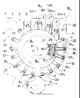
Fig. 1 shows an apparatus 10 according to the invention
by means of which flat supplementary products 2
provided with an adhesive are accepted from a first
conveyor 1 at. a pick-up point Al, transported along a
first path Bl to a discharge point A2 and are there
joined to the trailing side 92 of printed products 9,
which are guided in a suspended manner along a second
path B2 by a second conveyor 100.
The apparatus according to the invention has n holding
elements 201r 202, .... , 20n which are driven on the first
path Bl around a first axis x and by means of which the
supplementary products 2 are gripped individually at
the pick-up point Al, following appropriate rotation
about the first axis x are guided into the area of the
printed products 9 and are joined to a printed product
9m at the discharge point A2. For this purpose, the
holding elements 201r 202, .... , 20n are mounted such that
they can rotate about a second axis yi; y2; .... ;
yn
running at least approximately parallel to the first
axis x, so that the holding elements 201i 202r .... , 20n
can be rotated into a position suitable to pick up and
discharge the supplementary products 2 at the pick-up
and discharge points Al, A2.
CA 02329651 2000-12-27
- 5 -
The holding elements 201r 202, .... , 20õ are preferably
provided with. a suction head 201 (see e.g., Fig. 6),
which at the pick-up point Al is aligned at least
approximately parallel to the supplementary products 2
supplied and, at the discharge point A2 is aligned at
least approximately parallel to the printed products 9.
If the holding elements 201r 202, .... , 20n are equipped
with a gripper, a clamp or the like, their alignment at
the pick-up and discharge points Al, A2 must be adapted
accordingly.
At the pick-up point Al, the supplementary products 2
can be supplied by the first conveyor 1 or, as shown in
EP 0 675 061 131, Fig. 1, for example, taken directly
from a stack or, as shown in EP 0 666 186 Al, Fig. 5 or
WO 99/06285, Fig. 1, separated from a band or strip and
kept ready to be picked up or transferred immediately.
This band can be a supporting band, to which the
supplementary products 2 adhere and are detached
therefrom during the conveying operation. However, the
strip or the band can also form the basis of the
supplementary products 2, which are cut off from the
strip and provided with an adhesive 3, if the latter is
not already present.
In the preferable configurations of the invention shown
in Fig. 1 and Fig. 2, supplementary products 2 are
gripped at the pick-up point Al, if necessary at a
further pick-up point Al', are aligned vertically so as
to trail (see Fig. 1) or lead (see Fig. 2) during their
transport to the discharge point A2 by the holding
element 201; 202; .... ; 20n, are guided between the
printed products 9 and joined to a printed product 9m
at the discharge point A2.
The operation of discharging a supplementary product 2
onto a printed product 9m by means of a holding element
2 0n; 20n-1 leading and trailing and carrying the
CA 02329651 2000-12-27
- 6 -
supplementary product according to Fig. 1 will be
described in more detail below.
As shown in Figs. 3a - 3d, the holding element 20n-1
provided with the supplementary product 2 is guided
from the rear against the trailing side 92 of the
printed product 9m, while the leading holding element
20n is guided with a supporting element 202 against the
leading side 91 of the printed product 9m, until the
supplementary product 2 with the adhesive layer 3
applied to it is pressed firmly against the printed
product 9m supported by the leading holding element 20n
(see Fig. 3c). As Fig. 3d shows, the printed product 9m
provided with the supplementary product 2 is
subsequently released again. The holding element 20n_1
is guided back against the leading side 91 of the next
printed product 9m+1, to whose trailing side 92 a
supplementary product 2 is then applied by means of the
next trailing holding element 20n_2.
Each of the holding elements 201; 202; ....; 20õ therefore
has a dual function. During one revolution about the
axis x, a holding element 20n-1 transports a
supplementary product 2 from the pick-up point to the
discharge point Al; A2 and discharges it onto a printed
product 9m. In addition, at the discharge point A2, an
adjacent printed product 9m+i or 9m_1 is supported in
order that a supplementary product 2 can be applied to
it by means of a leading or trailing holding element
20n; 20n-2. In this case, the supporting function can be
carried out after the discharge of the supplementary
product 2 (see Fig. 1) or before the discharge of the
supplementary product 2 (see Fig. 2).
While in Fig. 1 the supplemeritary products 2 are fixed
to the trailing side 92 of the printed products 9, in
Fig. 2 they are fixed to the leading side 91 of the
printed products 9. Each holding element 201; 202; ...;
20n is therefore rotated in F'ig. 2, after picking up a
CA 02329651 2000-12-27
- 7 -
supplementary product 2, about the axis yl; y2; .... ; yõ
in such a way that the supplementary product 2 trails
the holding element 201; 202; ....; 20,, at the discharge
point A2, and, like the printed products 9, is aligned
at least approximately vertically.
The function of the elements belonging to the apparatus
which provide the movement (rotation about the second
axis y and inclination about a third axis z) of the
holding elements 201r 202, .... , 20n, which are
illustrated in a detail in Fig. 2, will be explained in
more detail below with reference to Fig. 6.
From Fig. 4, it can be seen that, by means of the
apparatus according to the invention, supplementary
products 2 can also be fixed to printed products 9
which have a number of limbs 93, 94. If the limbs 93,
94 are open, supplementary products 2 can also be fixed
to their inner sides 932, 941 in the manner described
above. Fig. 4 shows the holding elements 20n, 20n_1 of
the apparatus 1.0 during the joining of a supplementary
product 2 to the leading side 941 of a trailing limb 94
of a printed product 9. Here, it can be seen that the
supporting function is provided before the discharge of
the supplementary product 2.
Fig. 5 shows the holding elements 20,,, 20n_1 of the
apparatus 10 during the joining of a supplementary
product 2 to the trailing side 932 of a leading limb 93
of a printed product 9, which has been opened upstream
by means, for example, of measures disclosed by the
laid-open publication EP 0 564 812 Al.
Fig. 6 shows the apparatus 10 according to the
invention in a preferable configuration, with a holding
element 201 which is firmly connected to a shaft 21
that can be rotated about the second axis yl. The shaft
21 is rotatably mounted at both ends in levers 22, 22'
which, by mearis of shafts 23, 23' aligned along a third
CA 02329651 2000-12-27
- 8 -
axis zl, are rotatably connected to carrying elements
25, 25', which are fixed by means of flanged hubs 27,
27' to a drive shaft 11 aligned along the first axis x.
As illustrated in a detail in Fig. 6, the lever 22 is
provided with a wheel 26 which is spaced apart from the
third axis zl and which, during the rotation of the
carrying element 25 about the first axis x, which
rotation is preferably carried out at a constant
angular speed, is guided on a third path B3, which is
machined into a non-rotating slotted guide 40 aligned
parallel to the carrying element 25, as a guide groove
41.
The distance of the third path B3 from the first axis x
runs as a furiction of the angle of rotation about the
first axis x such that, in particular at the pick-up
point and the discharge point Al; A2, the pivoting or
inclination of the lever 22 needed to pick up or
discharge the supplementary products 2 is achieved.
In addition, in the preferred configuration, the shaft
21 is provided at both ends with a drive wheel 31; 31',
which is connected via a first drive belt 32; 32' to a
coupling wheel 33; 33' which is aligned at least
approximately coaxially with the third axis zl; zl' and
which is connected via a second drive belt 34; 34' to a
control wheel 35; 35' fixed to the carrying element 25;
25' . As shown in Fig. 2, the control wheel 35; 35' is
connected via a control lever 36 to a wheel 37 which,
during the rotation of the carrying element 25 about
the first axis x, is guided on a fourth path B4, which
is machined into the slotted guide 40 as a guide groove
42.
The distance of the fourth path B4 from the first axis
x is selected as a function of the angle of rotation
about the first axis x in such a way that, in
particular at the pick-up point and the discharge point
CA 02329651 2000-12-27
- 9 -
Al; A2, a rotation of the holding elements 201r 202,
20õ about the second axis yl; y2;....; yn, needed to pick
up and discharge the supplementary products 2, is
achieved.
Instead of the above described drive device with drive
wheel 31; 31', coupling wheel 33; 33' and control wheel
35, 35', which are connected to one another by the
first and second drive belts 32; 32' and 34; 34',
respectively, any desired further suitable drive means,
such as gearwheels, chains, etc., can be used for
controlling the position of the shaft 21.
In order to grip and hold supplementary products 2, the
holding elements 201r 202i...., 20n are provided with a
suction head 201, which is connected, via an ejector
203 serving as a jet pump with a suction action, to a
compressed-air device 15.
The compressed-air device 15 comprises a rotary valve
152 which is seated on the shaft 11, whose rotor is in
each case corinected via a lirie 153 to an ejector 203
and which, by means of a bearing, is rotatably mounted
in a stator connected to a compressed-air line 151 such
that an air duct for each holding element 201; 202; ...;
20n is formed in the rotary valve 152. The air pressure
(vacuum) within the suction element 201 is controlled
on the basis of the position of the holding elements
201r 202,...., 20n, so that at the pick-up point Al a
supplementary product 2 can be picked up by suction
and, after being transported, can be released again at
the discharge point A2. Instead of the above described
compressed-air device 15, by means of which the
necessary suction action is produced by increasing the
flow velocity in the ejectors 203, a negative pressure
system can also be used, by means of which the air is
sucked out of the ducts in the suction head 201 as
required.
CA 02329651 2000-12-27
- 10 -
By means of the apparatus according to the invention,
the supplementary products 2 can be applied to the
printed products 9 at any desired point. For this
purpose, the holding elements 201, 202, .... , 20n are
fixed to the associated shafts 21 at appropriately
selected positions. In additi_on, two or more holding
elements 201, 202, .... , 20n can be arranged on each shaft
21. As Fig. 2 shows, in addition a number of pick-up
points Al, Al' can be provided, at which supplementary
products 2 can be accepted f:rom first conveyors 1, 1'
arranged behind one another or beside one another. As
indicated in the drawing of Fig. 6, the holding
elements 201r 202, .... , 20n are aligned on the shaft 21
in accordance with the position of the first conveyors
1, 11.
The holding members 201r 202, .... , 20n can preferably be
controlled individually or in groups in such a way that
supplementary products 2 can optionally be accepted
from a first conveyor 1, 1' or from a stack at the
first or a further pick-up point Al, Al'.
The shafts 21 provided with the holding elements 201,
202, .... , 20õ are, as described above, preferably held at
both ends by carrying elements 25, 25' and levers 22,
22', and controlled by means of slotted guides 40, 40'
and drive means, for example the belt drive 30, 30'
shown in Fig. 6. However, the provision of holding
means and/or control means on only one side is also
possible.
Although the holding elements 201, 202, .... , 20n are
preferably provided with suction heads, the use of
gripping tools, such as clamps, is also possible. The
number of holding elements 201r 202, .... , 20n and shafts
21 is preferably selected such that a smooth transfer
of the supplementary products 2 at the pick-up and the
discharge poirlts Al, A2 can take place.
CA 02329651 2000-12-27
- 11 -
In the preferred configurations of the invention shown
in Fig. 1 - Fig. 6, the holding elements 201, 202,
20n have a dual function, being provided to hold a
supplementary product 2 and to support a printed
product 9. Also possible is the use of holding and
supporting elements which are provided alternately in
the apparatus and which, because of the reduced
functionality, can be controlled more simply, so that
their movement relative to the printed products 9 can
also be effected with other means. The holding members
201r 202, .... ., 20n shown, for example, in Fig. 1 are in
this case equipped alternately with only suction heads
201 or supporting elements 202.
If other means are provided to move the suction heads
201 and supporting elements 202, it may be possible to
dispense with the rotation about the second and/or
third axis y; z. The deflection of the suction heads
201 and supporting elements 202 can then, for example,
be carried out in another way, even pneumatically,
mechanically, electrically or magnetically.
The course of the first and second paths B1; B2, on
which the supplementary products 2 and the printed
products 9 are transported preferably runs
concentrically or coaxially with the axis x in the area
of the discharge point A2, in order that the transfer
can be made more easily and more precisely.
Although in the apparatus shown in Fig. 1 to Fig. 6 the
supplementary products 2 are inserted from below into
the area of the printed products 9, insertion from the
side or from above is likewise possible.
In addition, the supporting and holding elements can
run on paths separated from each other. The movement on
the first path Bl from the pick-up point Al to the
discharge point A2 is of course needed only for the
holding elements 201r 202, .... , 20n serving to transport
CA 02329651 2000-12-27
- 12 -
the supplementary products 2. A reduced number of
supporting elements can also be provided. At least one
supporting element is needed, and in each case is
provided on the side 91; 92 of the printed product 9
located opposite the holding element 201; 202; .... .; 20n
carrying a supplementary product 2 to be discharged, in
order to support said printed product 9.