Language selection

Search

Patent 2329876 Summary

Third-party information liability

Some of the information on this Web page has been provided by external sources. The Government of Canada is not responsible for the accuracy, reliability or currency of the information supplied by external sources. Users wishing to rely upon this information should consult directly with the source of the information. Content provided by external sources is not subject to official languages, privacy and accessibility requirements.

Claims and Abstract availability

Any discrepancies in the text and image of the Claims and Abstract are due to differing posting times. Text of the Claims and Abstract are posted:

  • At the time the application is open to public inspection;
  • At the time of issue of the patent (grant).
(12) Patent Application: (11) CA 2329876
(54) English Title: CABLE CONNECTOR FOR A SHIELDED CABLE
(54) French Title: CONNECTEUR DE CABLE POUR UN CABLE REVETU
Status: Deemed Abandoned and Beyond the Period of Reinstatement - Pending Response to Notice of Disregarded Communication
Bibliographic Data
(51) International Patent Classification (IPC):
  • H01R 13/631 (2006.01)
  • H01R 9/11 (2006.01)
  • H01R 12/00 (2006.01)
  • H01R 13/514 (2006.01)
  • H01R 13/516 (2006.01)
  • H01R 13/518 (2006.01)
  • H01R 13/58 (2006.01)
  • H01R 13/64 (2006.01)
  • H01R 13/645 (2006.01)
  • H01R 13/648 (2006.01)
  • H01R 13/658 (2011.01)
(72) Inventors :
  • VAN ZANTEN, ALBERTUS
(73) Owners :
  • F.C.I. - FRAMATOME CONNECTORS INTERNATIONAL
(71) Applicants :
  • F.C.I. - FRAMATOME CONNECTORS INTERNATIONAL (France)
(74) Agent: BKP GP
(74) Associate agent:
(45) Issued:
(22) Filed Date: 2000-12-28
(41) Open to Public Inspection: 2001-07-07
Availability of licence: N/A
Dedicated to the Public: N/A
(25) Language of filing: English

Patent Cooperation Treaty (PCT): No

(30) Application Priority Data:
Application No. Country/Territory Date
NL 1014035 (Netherlands (Kingdom of the)) 2000-01-07

Abstracts

English Abstract


ABSTRACT
The invention pertains to a connector for at least
one cable with one or more conductors, comprising at least
one housing of an electrically insulating material
containing contact elements that are connected or to be
connected to the conductors. The connector comprises a hood,
which at least partially accommodates the housing and which
comprises at least a passage for at least one cable, means
for connecting the hood to a support panel for a printed
circuit board, cable or the like, and one or more coding
protrusions on the side that, upon connection to the support
panel that is provided with holes for receiving
corresponding coding protrusions, faces the support panel.


Claims

Note: Claims are shown in the official language in which they were submitted.

CLAIMS
1. Connector (1; 18) for at least one cable (4)
with one or more conductors, comprising at least one housing
(2) of an electrically insulating material containing
contact elements that are connected or to be connected to
the conductors, characterised in that the connector (18)
comprises a hood (8), which at least partially accommodates
the housing (2) and which comprises at least a passage (10)
for at least one cable (4), means for connecting the hood
(8) to a support panel (20) for a printed circuit board,
cable or the like, and one or more coding protrusions (14)
on the side that, upon connection to the support panel (20),
faces the support panel (20) and wherein the front panel
(20) is provided with holes for receiving corresponding
coding protrusions.
2. Connector according to claim 1, wherein the hood
(8) accommodates two or more housings (2) of an electrically
insulating material, each housing (2) being provided with
contact elements that are connected or to be connected to
the conductors in their respective cables (4), and comprises
one of more passages (10) for the cables (4).
3. Connector according to claim 1 or 2, wherein the
conductors in the cable (4) comprise a common shielding and
wherein the connector further comprises a shielding (3) in
which the housing (2) is fitted and that is connected or to
be connected to the shielding of the cable (4).
4. Connector according to any one of the preceding
claims, wherein the hood (8) is shielded.
5. Connector according to claim 5, wherein the hood
(8) is made of a metal or a metallized plastic.
6. Connector according to claim 4 or 5, wherein the
hood (8) is undersized with respect to the one or more of
the shieldings (3) of the housings (2) of an electrically
insulating material.

8
7. Connector according to any one of the preceding
claims, wherein the hood comprises two or more openings (12)
and at least one removable element (13) comprising a coding
protrusion (14) which element (13) is placed in one of the
openings (12).
8. Hood (8) for use in a connector (18) according
to any one of the preceding claims, comprising a cavity (9)
for at least partially accommodating the housing (2) of a
connector (1), a passage (10) for a cable (4) connected to
the connector (1) and means (11) for connecting the hood (8)
to a support panel (20) for a printed circuit board, cable
or the like.
9. Hood (8) according to claim 8, which comprises
two or more openings (12) for receiving an element (13)
comprising a coding protrusion (14).
10. Hood according to any one of the preceding
claims, wherein the wall of the hood (8) near at least one
passage (10) extends into a strain relief for the respective
cable.

Description

Note: Descriptions are shown in the official language in which they were submitted.


CA 02329876 2000-12-28
w NL 2900/ c 2466-Aa/tk
Cable connector for a shielded cable.
--. The invention pertains to a connector for a cable
"_ with one or more conductors, comprising at least one housing
of an electrically insulating material containing contact
elements that are connected or to be connected to the
conductors.
Connectors of this kind are known, for example from
EP 0 907 221, and are, for instance, marketed by FCI
Electronics as round cable connectors of the MetralTM system.
Connectors of this kind are usually intended for connection
to a counterpart, e.g. a header if the connector is a
receptacle and vice versa, that is attached to a printed
circuit board or to the end of another cable. Thus, forces
exerted on the cable connector are transmitted to the said
counterpart and consequently to respectively the printed
circuit board or the other cable. The said printed circuit
boards or cables are often mounted in a frame, e.g. the
frame of a telephone exchange device. Such a frame can be
-- shielded itself so as to provide a Faraday cage or can be
- mounted in a suitable shielded casing. The frame comprises a
support panel, which in case of a shielded frame is also
referred to as a front panel, which comprises one or more
openings through which one or more cable connectors can be
connected to their counterparts.
The invention aims to provide a connector for a
cable of the above mentioned type, wherein the transmission
of forces exerted on the cable connector to its counterpart
is obviated or at least reduced considerably.
To this end, the connector according to the
invention is characterized in that the connector comprises a
hood, which at least partially accommodates the housing and
which comprises at least a passage for at least one cable,
means for connecting the hood to a support panel for a
printed circuit board, cable or the like, and one or more
coding protrusions on the side that, upon connection to the

CA 02329876 2000-12-28
u.,.,
.a .
2
support panel, faces the support panel and wherein the front
panel is provided with holes for receiving corresponding
coding protrusions.
Forces exerted on the connector according to the
present invention are transmitted through the hood to the
said support panel, whereas the transmission of forces to
.... the printed circuit board, cable or the like is avoided or
at least_reduced considerably. Further, the coding
protrusions can be located at specific positions
corresponding to specific holes in the front panel. Thus,
the chance of establishing incorrect connections through a
mix-up of connectors is avoided or at least reduced.
It is preferred that the hood accommodates two or
more housings, each housing being provided with contact
elements that are connected or to be connected to the
conductors in their respective cables. Many cable connectors
are available in a limited number of so-called position
modules. For instance, the above mentioned cable connector
according to the MetralT"' system is available in 5x1, 5x2,
5x4, 5x6 and 5x8 position modules. By using a hood that
accommodates two or more of these position modules, a large
number of different connectors can be assembled using
connector elements that are already available.
It is further preferred that, if the conductors
comprised in the cable are provided with a common shielding,
the hood is shielded, for instance by using a hood which is
made of a metal or a metallized plastic. By using a shielded
hood, the connector according to the present invention is
rendered front mountable. For instance, instead of usir~g the
connectors inside the shielded casing of a shielded
telephone exchange device, the said connectors can now be
connected directly to the front panel of the said device.
Using a shielded hood also renders the connector more
- suitable for use in applications that are sensitive to
Electro Magnetic Interference or EMI, such as devices
operating a high signal transfer rates.

' CA 02329876 2000-12-28
3
.,
The invention will be further explained by
reference to the drawings in which an embodiment of the
connector according to the present invention is
schematically shown.
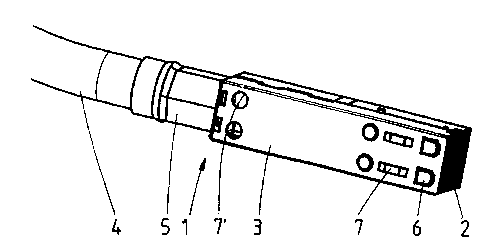
- 5 Fig. 1 shows a standard shielded connector for a
cable.
Fig. 2 shows a hood that can be slided over
-- standard_shielded connectors.
__ Fig. 3 shows a coding pin for use in the hood
according to fig. 2.
Fig. 4 shows the hood of fig. 2 which now
accommodates three standard connectors.
Fig. 5 shows six composite connectors according to
the present invention whilst attached to a front panel.
Fig. 1 shows a shielded round cable connector 1, in
this case a receptacle, comprising a housing 2 consisting of
multiple terminal blocks each of which has a minimum of 5x1
positions and, accordingly, comprises a minimum of 5x1
contact elements. The housing 2 is surrounded and held
together by a metal shield 3. The contact elements are
connected to conductors (twenty in all) in cable 4. The
metal shield 3 is electrically connected to the shielding of
the cable 4 by means of an inner ferrule and a shrink ring
5. Polarising ribs 6 on the housing 2 and springs 7 on the
metal shield 3 serve to align the connector 1 with a header
that is connected to a printed circuit board, cable or the
like. Polarising ribs 6 and springs 7 may serve as contacts
to support the grounding of the shield 3.
Fig. 2 shows a hood 8 in accordance with the ,
present invention. This particular hood 8 comprises a cavity
9 for accommodating one or more connectors. The hood 8 can
be manufactured by means of injection moulding a
thermoplastic material. The hood 8 can be provided with an
electrically conductive metal coating (not shown). Such
coatings are known to the person skilled in the art, and
may, for instance, comprise a copper layer with a thickness

' CA 02329876 2000-12-28
4
_ of say 1-2 ~ on which a nickel or aluminium of say 2-3~ has
I been deposited.
To ensure that effective electrical contact is
established between the shield of the connectors and the
shield of the hood 8, the cavity 9 of the hood 8 is
undersized with respect to the connectors which are to be
placed therein. The hood 8 comprises a passage 10 for the
---- cables of the connectors. Hood 8 further comprises two
diametrically opposed holes 11 for fastening screws. Other
fastening means can, of course, be used, e.g. latches or
resilient protrusions allowing a snap-fit connection.
The side of the hood 8 which, upon connection to a
printed circuit board, cable or the like, abuts the front
panel of a frame for supporting such a printed circuit
board, a cable or the like, is substantially rectangular.
Six openings 12 are provided along one of the long sides of
this rectangle for housing a coding means.
The hood 8 further comprises latches 12', which,
upon placing a connector 1 into the cavity 9, establish a
snap-fit connection with latch-holes 7' that are provided in
the shield 3 of the connector 1.
Also, a wall 12 " extends from the hood 8, which,
again upon placing one ore more connectors in the cavity 9,
supports the respective cables and limits the bending of the
cables near the actual connectors. Thus, the wall 12 "
provides a strain relief for each of the connectors placed
in the cavity 9.
Fig. 3 shows a suitable example of a coding means,
viz. coding pin 13, which comprises, on one of its ends a
protrusion 14 and a stop 15 which upon insertion of the
coding pin 13 in one of the openings 12 abuts the edge of
this opening and ensures that the protrusion 14 extends over
a predetermined distance below the lower surface of the hood
8. By using one or more of the coding pins 13, the shape of
the lower surface 16 of the hood 8 can be tailored to fit

CA 02329876 2000-12-28
corresponding openings or recesses in the front plate of the
mentioned frame.
Fig. 4 shows the hood 8 of fig. 2 which has now
been slided over two 4x5 connectors 1 (as shown in fig. 1)
5 on the left hand and right hand side and a 6x5 connector 17
in the middle, thus obtaining a non-standard 14x5 connector
18.
-. _Fig. 5 shows six of the connectors 18 as shown in
_. fig. 4 attached by means of fastening screws 19 to a front
panel 20. Each of the connectors 18 comprises a single
coding pin 13 placed in a different hole for each of the
connectors 18. Corresponding holes are provided in the front
panel 20 thus making sure that the connectors 18 are not
interchangeable.
From fig. 5 it will be clear that forces exerted on
the cables extending through the passages 10 of the
connectors 18 will be transmitted to the edge of the
passages 10 and not to the headers and the printed circuit
boards, cables or the like, to which these headers are
attached. The said forces will be transmitted through the
hoods to the front panel 20.
A further advantage of the connector according to
the present invention resides in that connectors comprising
a non-standard number of positions can be assembled
efficiently and at will, especially if the individual
connectors are end-to-end stackable.
If the hood is shielded, the connectors according
to the invention can be front mounted on a frame or casing
of e.g. a telephone exchange device. A further advantage of
the connector according to the invention resides in that
connectors comprising a large number of positions do not
have a single, rigid cable comprising the same number of
conductors but, instead, comprise a number of more flexible
cables comprising a lesser number of conductors.
It should be noted that instead of attaching
protrusions or coding pins to the hood and providing

' CA 02329876 2000-12-28
6
recesses in the front panel, it is also possible to provide
protrusions or coding pins on the front panel and provide
corresponding recesses in the hood.
The invention is not restricted to the above
described embodiment which can be varied in a number of ways
within the scope of the invention.

Representative Drawing
A single figure which represents the drawing illustrating the invention.
Administrative Status

2024-08-01:As part of the Next Generation Patents (NGP) transition, the Canadian Patents Database (CPD) now contains a more detailed Event History, which replicates the Event Log of our new back-office solution.

Please note that "Inactive:" events refers to events no longer in use in our new back-office solution.

For a clearer understanding of the status of the application/patent presented on this page, the site Disclaimer , as well as the definitions for Patent , Event History , Maintenance Fee  and Payment History  should be consulted.

Event History

Description Date
Inactive: IPC from PCS 2022-09-10
Inactive: First IPC from PCS 2022-09-10
Inactive: IPC from PCS 2022-09-10
Inactive: IPC expired 2011-01-01
Time Limit for Reversal Expired 2006-12-28
Application Not Reinstated by Deadline 2006-12-28
Inactive: IPC from MCD 2006-03-12
Deemed Abandoned - Failure to Respond to Maintenance Fee Notice 2005-12-28
Inactive: Abandon-RFE+Late fee unpaid-Correspondence sent 2005-12-28
Inactive: Office letter 2002-12-13
Appointment of Agent Requirements Determined Compliant 2002-12-13
Revocation of Agent Requirements Determined Compliant 2002-12-13
Inactive: Office letter 2002-12-13
Revocation of Agent Request 2002-11-27
Appointment of Agent Request 2002-11-27
Revocation of Agent Request 2002-11-25
Appointment of Agent Request 2002-11-25
Inactive: Cover page published 2001-07-10
Application Published (Open to Public Inspection) 2001-07-07
Letter Sent 2001-04-18
Inactive: Single transfer 2001-03-13
Inactive: IPC assigned 2001-02-20
Inactive: First IPC assigned 2001-02-20
Inactive: Courtesy letter - Evidence 2001-02-13
Inactive: Filing certificate - No RFE (English) 2001-02-06
Filing Requirements Determined Compliant 2001-02-06
Application Received - Regular National 2001-02-05

Abandonment History

Abandonment Date Reason Reinstatement Date
2005-12-28

Maintenance Fee

The last payment was received on 2004-11-01

Note : If the full payment has not been received on or before the date indicated, a further fee may be required which may be one of the following

  • the reinstatement fee;
  • the late payment fee; or
  • additional fee to reverse deemed expiry.

Please refer to the CIPO Patent Fees web page to see all current fee amounts.

Fee History

Fee Type Anniversary Year Due Date Paid Date
Application fee - standard 2000-12-28
Registration of a document 2001-03-13
MF (application, 2nd anniv.) - standard 02 2002-12-30 2002-11-27
MF (application, 3rd anniv.) - standard 03 2003-12-29 2003-11-13
MF (application, 4th anniv.) - standard 04 2004-12-28 2004-11-01
Owners on Record

Note: Records showing the ownership history in alphabetical order.

Current Owners on Record
F.C.I. - FRAMATOME CONNECTORS INTERNATIONAL
Past Owners on Record
ALBERTUS VAN ZANTEN
Past Owners that do not appear in the "Owners on Record" listing will appear in other documentation within the application.
Documents

To view selected files, please enter reCAPTCHA code :


To view images, click a link in the Document Description column. To download the documents, select one or more checkboxes in the first column and then click the "Download Selected in PDF format (Zip Archive)" or the "Download Selected as Single PDF" button.

List of published and non-published patent-specific documents on the CPD .

If you have any difficulty accessing content, you can call the Client Service Centre at 1-866-997-1936 or send them an e-mail at CIPO Client Service Centre.


Document
Description 
Date
(yyyy-mm-dd) 
Number of pages   Size of Image (KB) 
Representative drawing 2001-07-09 1 7
Cover Page 2001-07-09 1 36
Description 2000-12-28 6 261
Claims 2000-12-28 2 72
Abstract 2000-12-28 1 20
Drawings 2000-12-28 2 58
Filing Certificate (English) 2001-02-06 1 162
Courtesy - Certificate of registration (related document(s)) 2001-04-18 1 113
Reminder of maintenance fee due 2002-08-29 1 109
Reminder - Request for Examination 2005-08-30 1 116
Courtesy - Abandonment Letter (Request for Examination) 2006-03-08 1 167
Courtesy - Abandonment Letter (Maintenance Fee) 2006-02-22 1 174
Correspondence 2001-02-05 1 25
Correspondence 2002-11-25 3 89
Correspondence 2002-12-13 1 14
Correspondence 2002-12-13 1 16
Fees 2001-11-27 2 51
Fees 2003-11-13 1 35
Fees 2004-11-01 1 30