Language selection

Search

Patent 2330397 Summary

Third-party information liability

Some of the information on this Web page has been provided by external sources. The Government of Canada is not responsible for the accuracy, reliability or currency of the information supplied by external sources. Users wishing to rely upon this information should consult directly with the source of the information. Content provided by external sources is not subject to official languages, privacy and accessibility requirements.

Claims and Abstract availability

Any discrepancies in the text and image of the Claims and Abstract are due to differing posting times. Text of the Claims and Abstract are posted:

  • At the time the application is open to public inspection;
  • At the time of issue of the patent (grant).
(12) Patent: (11) CA 2330397
(54) English Title: AIRCRAFT AIRFOIL LEADING EDGE MEMBER EQUIPPED WITH A DE-ICING DEVICE
(54) French Title: PIECE DE BORD D'ATTAQUE DE LA SURFACE PORTANTE D'UN AERONEF MUNIE D'UN DISPOSITIF DE DEGIVRAGE
Status: Expired and beyond the Period of Reversal
Bibliographic Data
(51) International Patent Classification (IPC):
  • B64D 15/02 (2006.01)
  • B64D 33/00 (2006.01)
(72) Inventors :
  • LAUGT, PAUL (France)
(73) Owners :
  • DASSAULT AVIATION
(71) Applicants :
  • DASSAULT AVIATION (France)
(74) Agent: SMART & BIGGAR LP
(74) Associate agent:
(45) Issued: 2008-10-28
(22) Filed Date: 2001-01-09
(41) Open to Public Inspection: 2001-07-17
Examination requested: 2006-01-06
Availability of licence: N/A
Dedicated to the Public: N/A
(25) Language of filing: English

Patent Cooperation Treaty (PCT): No

(30) Application Priority Data:
Application No. Country/Territory Date
00 00525 (France) 2000-01-17

Abstracts

English Abstract

A leading edge member (1a) of an airfoil (V) of an aircraft has an outside wall (5a) and a de-icing device of the type for circulating hot air in the direction of the span of said airfoil. Said device includes a) a hot air distribution duct (15a) extending inside said leading edge member in said direction and having a plurality of orifices (25a) distributed over at least part of its length, and b) hot air supply means (19a) communicating with one end (17a) of said distribution duct (15a; 15b). Said hot air supply means (19a) are adapted to be connected by ducts (C) located outside said leading edge member to at least one propulsion engine (M) of said aircraft.


French Abstract

Une pièce de bord d'attaque (1a) d'une surface portante (V) d'un aéronef a une paroi extérieure (5a) et un dispositif de dégivrage du type qui sert à la circulation de l'air chaud dans la direction de l'envergure de ladite surface portante. Ledit dispositif comprend a) une canalisation de distribution d'air chaud (15a) qui traverse ladite pièce de bord d'attaque dans ladite direction et ayant une pluralité d'orifices (25a) disposés sur au moins une partie de sa longueur, et b) un dispositif d'approvisionnement d'air chaud (19a) qui communique avec une extrémité (17a) de ladite canalisation de distribution (15a; 15b). Lesdits dispositifs d'approvisionnement d'air chaud (19a) sont adaptés pour être reliés par des canalisations (C) situées à l'extérieur de la pièce de bord d'attaque à au moins un moteur de propulsion (M) dudit aéronef.

Claims

Note: Claims are shown in the official language in which they were submitted.

6
What is claimed is:
1. A leading edge member of an airfoil of an aircraft having an outside
wall and a de-icing device for circulating hot air in a direction of a span of
said
airfoil, said de-icing device comprising a hot air distribution duct extending
longitudinally inside said leading edge member in said direction of said span
and spaced from said outside wall, said distribution duct having two open
ends defining a length of said duct with a plurality of orifices distributed
over at
least a part of said length between said two ends and, a hot air supply duct
communicating with one of said ends of said distribution duct for hot air flow
through said distribution duct and longitudinally along said outside wall,
said
hot air supply duct connected to at least one propulsion engine of said
aircraft.
2. The leading edge member of an airfoil according to claim 1, wherein
said hot air supply duct includes a hot air injector discharging into an
interior
at said one end of said distribution duct and defining a passage therewith.
3. The leading edge member of an airfoil according to claim 1, wherein
the other end of said distribution duct is open.
4. The leading edge member of an airfoil according to claim 1, wherein
said distribution duct is fixed at said one end to a structure of said leading
edge member and said distribution duct is held in position over the remainder
of its length by slide means.
5. The leading edge member of an airfoil according to claim 1,
comprising:
a first compartment inside the leading edge of said leading edge
member and containing said distribution duct for de-icing said leading edge,
a second compartment located under a top surface of said leading
edge member, for de-icing said top surface,
a third compartment for collecting said hot air, and
said first and second compartments communicating with each other, and said
second and third compartments communicating with each other.

7
6. The leading edge member of an airfoil according to claim 5, wherein
said leading edge member is mobile, said hot air supply duct includes a
telescopic tube part, and said third compartment is located substantially
between said first compartment and said second compartment.
7. The leading edge member of an airfoil according to claim 6, wherein
said leading edge member further includes a fourth compartment located
substantially between said first compartment and a fixed part of said airfoil
and communicating with the outside, and
a substantially E-shaped spar fixed to the inside of said leading edge
member, said E-shaped spar forming said first compartment, second
compartment, third compartment and fourth compartment, and having first hot
air passages between the first compartment and the second compartment and
second hot air passages between said third compartment and said fourth
compartment,
an outside section fixed to a top part of said E-shaped spar and to the
top surface of said leading edge member, having third hot air passages
between said second compartment and said third compartment, and
an inside section fixed to a median part of said E-shaped spar and to
said outside section and to the top surface of the leading edge member.
8. The leading edge member of an airfoil according to claim 7, wherein
said first passages are established by first embossing on the top part of said
E-shaped spar, said second passages are established by second embossing
on the median part of said E-shaped spar, and said third passages are
established by grooves or orifices on said outside section.
9. The leading edge member of an airfoil according to claim 5, wherein
said leading edge member is fixed and said third compartment is located
substantially above said bottom surface of said airfoil and said third
compartment communicates with the outside.

8
10. The leading edge member of an airfoil according to claim 9, further
comprising:
a substantially C-shaped spar fixed to the inside of said leading edge
member, said C-shaped spar forming said first compartment, second
compartment and third compartment, and having first hot air passages
between said first compartment and said second compartment and second
hot air passages between said second compartment and said third
compartment, and
sections fixed to said C-shaped spar, to said top surface and to said
bottom surface of said leading edge member.
11. The leading edge member of an airfoil according to claim 10, wherein
said first and second passages are respectively established by first and
second embossing on said C-shaped spar.
12. An airfoil of an aircraft, comprising a leading edge member having an
outside wall, a first compartment along said outside wall and a de-icing
device
for circulating hot air in a longitudinal direction of a span of said airfoil,
said
de-icing device including a hot air distribution duct extending inside said
first
compartment in said longitudinal direction of said span and spaced from said
outside wall, said duct having two open ends defining a length of said duct
with a plurality of orifices distributed over at least a part of said length
between said two ends, and a hot air supply duct communicating with one of
said ends of said distribution duct for flowing hot air longitudinally through
said
distribution duct and along said first compartment, said hot air supply duct
connected to at least one propulsion engine of said aircraft.
13. An aircraft comprising an airfoil having a leading edge member having
an outside wall, a first compartment along said outside wall and a de-icing
device for circulating hot air in a longitudinal direction of a span of said
airfoil,
said de-icing device including a hot air distribution duct extending inside
said
first compartment in said longitudinal direction of said span and spaced from
said outside wall, said duct having two open ends defining a length of said
duct with a plurality of orifices distributed over at least a part of said
length

9
between said two ends, and a hot air supply duct communicating with one of
said ends of said distribution duct for flowing hot air longitudinally through
said
distribution duct and said first compartment, said hot air supply duct
connected to at least one propulsion engine of said aircraft.
14. The airfoil of an aircraft, according to claim 12, wherein said hot air
supply duct includes a hot air injector discharging into an interior at said
one
end of said distribution duct and defining a passage therewith.
15. The airfoil of an aircraft, according to claim 12, further comprising:
a second compartment located under a top surface of said leading
edge member for de-icing said top surface,
a third compartment for collecting said hot air, and
said first and second compartments communicating with each other, and said
second and third compartments communicating with each other.
16. The airfoil of an aircraft, according to claim 15, further comprising:
a substantially C-shaped spar fixed to the inside of said leading edge
member, said C-shaped spar forming said first compartment, second
compartment and third compartment, and having first hot air passages
between said first compartment and said second compartment and second
hot air passages between said second compartment and said third
compartment, and
sections fixed to said C-shaped spar, to said top surface and to said
bottom surface of said leading edge member.
17. The aircraft according to claim 13, wherein said hot air supply duct
includes a hot air injector discharging into an interior at said one end of
said
distribution duct and defining a passage therewith.
18. The aircraft according to claim 13, further comprising:
a second compartment located under a top surface of said leading
edge member, for de-icing said top surface,
a third compartment for collecting said hot air, and

said first and second compartments communicating with each other, and said
second and third compartments communicating with each other.
19. The aircraft according to claim 17, wherein said leading edge member
is mobile, said hot air supply means include a telescopic tube part, and said
third compartment is located substantially between said first compartment and
said second compartment.
20. The aircraft according to claim 19, wherein said leading edge member
further includes a fourth compartment located substantially between said first
compartment and the fixed part of said airfoil and communicating with the
outside, and
a substantially E-shaped spar fixed to the inside of said leading edge
member, said E-shaped spar forming said first compartment, second
compartment, third compartment and fourth compartment, and having first hot
air passages between the first compartment and the second compartment and
second hot air passages between said third compartment and said fourth
compartment,
an outside section fixed to a top part of said E-shaped spar and to the
top surface of said leading edge member, having third hot air passages
between said second compartment and said third compartment, and
an inside section fixed to a median part of said E-shaped spar and to
said outside section and to the top surface of the leading edge member.

Description

Note: Descriptions are shown in the official language in which they were submitted.


CA 02330397 2001-01-09
1
Aircraft airfoil leading edge member eguipped with a de-icing device
The present invention relates to an aircraft airfoil leading edge member
equipped with a de-icing device, to an airfoil equipped with that leading edge
member,
and to an aircraft equipped with that airfoil.
The expression "airfoil leading edge member" refers to a fixed or mobile
member forming at least part of the leading edge of the airfoil.
US patent 4,741,499 discloses an airfoil leading edge member having an
outside wall and a de-icing device of the type for circulating hot air in the
direction of the
span of said airfoil, said device including a) a hot air distribution duct
extending inside
said leading edge member in said direction and having a plurality of orifices
distributed
over at least part of its length, and b) hot air supply means communicating
with one end
of said distribution duct.
The above prior art system combats the formation of ice on an airfoil leading
edge member in a relatively effective manner.
However, in the above prior art system, the hot air supply means include a
heating unit and a blower located inside the airfoil leading edge member for
heating and
circulating the hot air in a closed circuit inside the airfoil leading edge
member.
In the above system energy from the propulsion engines of the aircraft must be
converted into electrical energy to supply the heating units and the blowers
and that
electrical energy must then be converted into heat energy. In the final
analysis there is
therefore a great loss of energy which adversely affects the fuel consumption
of the
aircraft.
An object of the present invention is to eliminate the drawbacks mentioned
above.
This object of the invention is achieved with a leading edge member of an
aircraft airfoil having an outside wall and a de-icing device of the type for
circulating hot
air in the direction of the span of said airfoil, said device including a) a
hot air distribution
duct extending inside said leading edge member in said direction and having a
plurality
of orifices distributed over at least part of its length, and b) hot air
supply means
communicating with one end of said distribution duct, characterized in that
said hot air
supply means are adapted to be connected by at least one duct located outside
said
leading edge member to at least one propulsion engine of said aircraft.
Because of the above features, hot air coming directly from the engines of the
aircraft can be used for de-icing, which avoids the energy losses inherent to
the prior art
system.

CA 02330397 2001-01-09
2
The present invention also provides:
- an aircraft airfoil that is noteworthy in that it includes a leading edge
member
as defined above, and
- an aircraft that is noteworthy in that it includes an airfoil as defined
above.
Other features and advantages of the present invention will become apparent
on reading the following description and examining the accompanying drawings,
in
which:
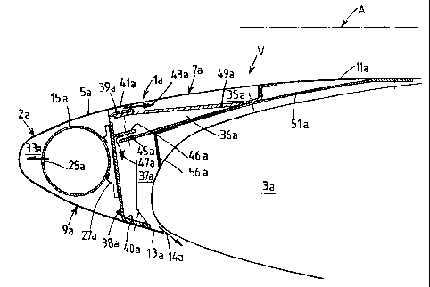
- figure 1 is a view in cross section of a mobile airfoil leading edge member
according to the invention,
- figure 2 is a plan view of the mobile airfoil leading edge member from
figure 1
with the wall part forming the top surface of the leading edge member removed,
and
- figure 3 is a view in cross section of a fixed airfoil leading edge member
according to the invention.
In figures 1 and 2 the reference numbers bear the suffix a; in figure 3 they
bear
the suffix b.
Identical reference numbers designate identical or similar units or sets of
units.
In the following description, the terms "upper", "lower", "above" and "below"
must be understood as referring to the top and bottom edges of the appended
drawing
sheets being vertically at the top and at the bottom, respectively.
Figures 1 and 2 show a mobile leading edge member 1a according to the
invention forming part of a leading edge 2a of an airfoil V of an aircraft A.
The term "mobile" signifies that the leading edge member can slide on rails
(not
shown) to a position away from the fixed part of the airfoil 3a to increase
the lift of the
aircraft, especially during landing.
The mobile leading edge member la is formed by a single outside wall 5a
defining a top surface 7a, a bottom surface 9a and a tail 11a.
The end 13a of the bottom surface 9a and the fixed part of the airfoil 3a have
a
clearance 14a between them.
Inside the leading edge member 1a is a de-icing device including a hot air
distribution duct 15a extending along the direction of the leading edge member
la, i.e. in
the direction of the span of the airfoil V.
As can be seen in figure 2, hot air supply means can include an injector 19a
and a telescopic tube part 20a communicating with one end 17a of the duct 15a.
According to one essential feature of the invention, the hot air supply means
are
adapted to be connected by at least one duct C outside the leading edge member
1a to

CA 02330397 2001-01-09
3
at least one propulsion engine M of the aircraft A.
The injector 19a forms a passage 21 a with the duct 15a. The other end 23a of
the duct 15a is open.
The duct 15a has orifices 25a distributed over at least part of its length,
preferably over its entire length. The orifices preferably face the leading
edge 2a (see
figures 1 and 2).
The end 17a of the duct 15a is preferably fixed to the structure of the
leading
edge member and the rest of its length is held in position by slides 27a (see
figure 1).
As can be seen in figures 1 and 2, the mobile leading edge member 1 a
includes a first compartment 33a on the inside of the leading edge member 2a
and
containing the distribution duct 15a, a second compartment 35a located under
the top
surface 7a, a third compartment 36a located substantially between the first
and second
compartments 33a and 35a, and a fourth compartment 37a located substantially
between the first compartment 33a and the fixed part 3a of the airfoil.
The compartments are formed by:
- a spar 38a whose section is substantially E-shaped with the top and bottom
parts 39a and 40a respectively fixed to the top surface 7a and the bottom
surface 9a,
having first embossing 41a formed on the top part 39a of the E and defining
hot air
passages 43a between the first and second compartments 33a and 35a and second
embossing 45a formed on the median part 46a of the E and defining hot air
passages
47a between the third and fourth compartments 36a and 37a,
- an outside section 49a fixed to the top part 39a of the E and to the top
surface
7a of the leading edge member 1a, and
- an inside section 51 a fixed to the median part 46a of the E and to the
outside
section 49a and to the top surface 7a of the leading edge member 1a.
As can be seen in figure 2, the outside section 49a has hot air passages 55a
(formed by grooves or orifices, for example) in the vicinity of the injector
19a between the
second and third compartments 35a and 36a.
An insulating seal 56a is placed between the inside section 51a and the fixed
airfoil part 3a.
Figure 3 shows a leading edge member 1 b fixed to the fixed airfoil part 3b.
As can be seen in the figure, the fixed leading edge member 1 b differs from
the
mobile leading edge member 1a essentially in that the compartments in the
latter are a
different shape.
The fixed leading edge member includes a first compartment 33b inside the

CA 02330397 2001-01-09
4
leading edge 2b and containing the distribution duct 15b, a second compartment
35b
located under the top surface 7b, and a third compartment 36b located above
the bottom
surface 9b.
The above compartments are formed by:
- a spar 38b whose section is substantially C-shaped fixed to the inside of
the
leading edge member, having first embossing 41b forming hot air passages 43b
between the first and second compartments 33b and 35b and second embossing 45b
forming hot air passages 47b between the second and third compartments 35b and
36b,
and
- sections 57b fixed to the C-shaped spar 38b, to the top surface 7b and to
the
bottom surface 9b of the leading edge member 1 b.
The outside wall 5b includes, in the bottom part of sections 57b, orifices 58b
defining hot air passages 60b between the third compartments 36b and a box
section
(not shown) for channeling the hot air to the vicinity of the fuselage.
As in the case of the mobile leading edge member 1a, the hot air supply means
can include an injector (not shown) communicating with one end of the duct
15b.
The injector is adapted to be connected by at least one duct to at least one
propulsion engine of the aircraft.
Because the leading edge member lb is fixed, it is not necessary to provide
any telescopic tube part.
The operation and the advantages of the airfoil leading edge member according
to the invention follow directly from the preceding description.
The path followed by the hot air is indicated by arrows in figures 1 to 3.
In the case of the mobile leading edge member la (see figure 2), the hot air
from the propulsion engine M reaches the duct 15a via the duct C, the
telescopic tube
part 20a and the injector 19a.
The hot air then leaves the duct 15a in the first compartment 33a via the open
end 23a and via the orifices 25a and flows in contact with the outside wall
5a, which de-
ices the leading edge 2a of the leading edge member 1a.
The hot air can then either flow back inside the distribution duct 15a through
the
passage 21 a or flow into the second compartment 35a via the passages 43a (see
figures
1 and 2).
In the latter case the hot air de-ices the top surface 7a of the leading edge
member 1 a as it flows directly along the wall 2a.
It then returns to the third compartment 36a via the passages 55a at the end
of

CA 02330397 2001-01-09
the leading edge member (see figure 2) and then passes through the passages
47a (see
figure 1) to return to the fourth compartment 37a and finally to escape to the
outside
through the clearance 14a.
In the case of the fixed leading edge member 1 b(see figure 3), the path
5 followed by the hot air is substantially the same: after reaching the second
compartment
35b via the passages 43b, the hot air returns to the third compartment 36b
through the
passages 47b and then passes through the passages 60b before it returns to the
box
section (not shown) which conveys the air to the vicinity of the fuselage.
As will now be clear, the airfoil leading edge member according to the
invention
enables direct use of hot air from the engines of the aircraft for de-icing,
which avoids the
energy losses inherent to the prior art system, and so reduces the additional
consumption of fuel for de-icing purposes.
Of course, the present invention is not limited to the embodiments described
as
shown, which are provided by way of illustrative and non-limiting example.

Representative Drawing
A single figure which represents the drawing illustrating the invention.
Administrative Status

2024-08-01:As part of the Next Generation Patents (NGP) transition, the Canadian Patents Database (CPD) now contains a more detailed Event History, which replicates the Event Log of our new back-office solution.

Please note that "Inactive:" events refers to events no longer in use in our new back-office solution.

For a clearer understanding of the status of the application/patent presented on this page, the site Disclaimer , as well as the definitions for Patent , Event History , Maintenance Fee  and Payment History  should be consulted.

Event History

Description Date
Time Limit for Reversal Expired 2018-01-09
Letter Sent 2017-01-09
Grant by Issuance 2008-10-28
Inactive: Cover page published 2008-10-27
Inactive: Final fee received 2008-08-13
Pre-grant 2008-08-13
Notice of Allowance is Issued 2008-04-17
Letter Sent 2008-04-17
Notice of Allowance is Issued 2008-04-17
Inactive: IPC assigned 2008-04-15
Inactive: IPC removed 2008-04-15
Inactive: First IPC assigned 2008-04-15
Inactive: IPC assigned 2008-04-15
Inactive: Approved for allowance (AFA) 2008-02-20
Amendment Received - Voluntary Amendment 2006-06-27
Letter Sent 2006-01-23
Request for Examination Requirements Determined Compliant 2006-01-06
All Requirements for Examination Determined Compliant 2006-01-06
Request for Examination Received 2006-01-06
Amendment Received - Voluntary Amendment 2006-01-05
Inactive: Cover page published 2001-07-25
Application Published (Open to Public Inspection) 2001-07-17
Inactive: First IPC assigned 2001-03-30
Inactive: Courtesy letter - Evidence 2001-03-06
Inactive: Filing certificate - No RFE (English) 2001-02-09
Filing Requirements Determined Compliant 2001-02-09
Letter Sent 2001-02-09
Application Received - Regular National 2001-02-08

Abandonment History

There is no abandonment history.

Maintenance Fee

The last payment was received on 2007-12-19

Note : If the full payment has not been received on or before the date indicated, a further fee may be required which may be one of the following

  • the reinstatement fee;
  • the late payment fee; or
  • additional fee to reverse deemed expiry.

Please refer to the CIPO Patent Fees web page to see all current fee amounts.

Owners on Record

Note: Records showing the ownership history in alphabetical order.

Current Owners on Record
DASSAULT AVIATION
Past Owners on Record
PAUL LAUGT
Past Owners that do not appear in the "Owners on Record" listing will appear in other documentation within the application.
Documents

To view selected files, please enter reCAPTCHA code :


To view images, click a link in the Document Description column. To download the documents, select one or more checkboxes in the first column and then click the "Download Selected in PDF format (Zip Archive)" or the "Download Selected as Single PDF" button.

List of published and non-published patent-specific documents on the CPD .

If you have any difficulty accessing content, you can call the Client Service Centre at 1-866-997-1936 or send them an e-mail at CIPO Client Service Centre.


Document
Description 
Date
(yyyy-mm-dd) 
Number of pages   Size of Image (KB) 
Representative drawing 2001-07-24 1 11
Cover Page 2001-07-24 1 38
Description 2001-01-09 5 224
Claims 2001-01-09 3 116
Drawings 2001-01-09 2 36
Abstract 2001-01-09 1 19
Claims 2006-01-05 5 222
Representative drawing 2008-10-08 1 12
Cover Page 2008-10-08 1 41
Courtesy - Certificate of registration (related document(s)) 2001-02-09 1 113
Filing Certificate (English) 2001-02-09 1 162
Reminder of maintenance fee due 2002-09-10 1 109
Reminder - Request for Examination 2005-09-12 1 116
Acknowledgement of Request for Examination 2006-01-23 1 176
Commissioner's Notice - Application Found Allowable 2008-04-17 1 164
Maintenance Fee Notice 2017-02-20 1 178
Fees 2003-01-06 4 223
Fees 2003-12-10 1 36
Fees 2004-11-30 1 34
Fees 2005-12-13 1 30
Correspondence 2008-08-13 1 31