Note: Descriptions are shown in the official language in which they were submitted.
CA 02330629 2000-10-26
WO 99/58973 PCT/US99/10377
METHOD AND DEVICE FOR PREDICTING PHYSIOLOGICAL VALUES
Field of the Invention
The invention relates generally to a method and
device for measuring the concentration of target
chemical analytes present in a biological system. More
particularly, the invention relates to a method and
device for predicting a future or past concentration of
an analyte using a series of measurements obtained from
a monitoring system. One important application of the
invention involves predicting future or past blood
glucose concentrations.
Background of the Invention
The generally accepted methods for time series
forecasting are: extrapolation of linear regression,
extrapolation of polynomial regression, autoregressive
moving average (ARMA), and exponential smoothing as
discussed by Diggle, Time Series: A Biostatistical
Introduction, Oxford University Press, Oxford, (1990).
Linear regression models are an acceptable means of
forecasting, provided that the data being analyzed are
linear. In the case where the data in question are
nonlinear, polynomial regression is often used to model
the data.
Autoregressive (ARMA) methods have been used with
success in forecasting where the underlying phenomena
are stationary (or can be converted to stationary), with
superimposed fluctuations expressible as random white
3o noise. These two requirements can be met for some
CA 02330629 2000-10-26
WO 99/58973 PCT/US99/10377
physiologic variables, but plasma glucose levels in
diabetic patients generally do not fit these
requirements. The method of exponential smoothing is a
special case of the ARMA method. The above methods
forecast the future value of a variable based on the
value of that variable at previous time points.
Information on the first and second derivative of the
variable with respect to time is not included.
Inclusion of these time derivatives can substantially
increase the accuracy of the forecasting method in the
situation where the future value of a variable depends
on its time rate of change.
Summary of the Invention
The present invention provides a method and device
for continually or continuously measuring the
concentration of an analyte present in a biological
system. The method entails continually or continuously
detecting a raw signal from the biological system,
wherein the raw signal is specifically related to the
analyte. As the raw signals are obtained, a calibration
step is performed to correlate raw signal with a
measurement value indicative of the concentration of
analyte present in the biological system. These steps
of detection and calibration are used to obtain a series
of measurement values at selected time intervals. In a
preferred embodiment, the selected time intervals are
evenly spaced. Once the series of measurement values is
obtained, the method of the invention provides for the
prediction of a measurement value at a further time
interval which occurs either one time interval before,
or one time interval after, the series of measurement
2
CA 02330629 2000-10-26
WO 99/58973 PCTIUS99/10377
values is obtained.
The raw signal can be obtained using any suitable
sensing methodology including, for example, methods
which rely on direct contact of a sensing apparatus with
the biological system; methods which extract samples
from the biological system by invasive, minimally
invasive, and non-invasive sampling techniques, wherein
the sensing apparatus is contacted with the extracted
sample; methods which rely on indirect contact of a
sensing apparatus with the biological system; and the
like. In preferred embodiments of the invention,
methods are used to extract samples from the biological
sample using minimally invasive or non-invasive sampling
techniques. The sensing apparatus used with any of the
above-noted methods can employ any suitable sensing
element to provide the raw signal including, but not
limited to, physical, chemical, electrochemical,
photochemical, spectrophotometric, polarimetric,
colorimetric, radiometric, or like elements. In
preferred embodiments of the invention, a biosensor is
used which comprises an electrochemical sensing element.
In one particular embodiment of the invention, the
raw signal is obtained using a transdermal sampling
system that is placed in operative contact with a skin
or mucosal surface of the biological system. The
sampling system transdermally extracts the analyte from
the biological system using any appropriate sampling
technique, for example, iontophoresis. The transdermal
sampling system is maintained in operative contact with
the skin or mucosal surface of the biological system to
provide for such continual or continuous analyte
measurement.
3
CA 02330629 2000-10-26
WO 99/58973 PCT/US99/10377
The analyte can be any specific substance or
component that one is desirous of detecting and/or
measuring in a chemical, physical, enzymatic, or optical
analysis. Such analytes include, but are not limited
to, amino acids, enzyme substrates or products
indicating a disease state or condition, other markers
of disease states or conditions, drugs of abuse,
therapeutic and/or pharmacologic agents, electrolytes,
physiological analytes of interest (e. g., calcium,
potassium, sodium, chloride, bicarbonate (C02), glucose,
urea (blood urea nitrogen), lactate, hematocrit, and
hemoglobin), lipids, and the like. In preferred
embodiments, the analyte is a physiological analyte of
interest, for example glucose, or a chemical that has a
physiological action, for example a drug or
pharmacological agent.
A wide variety of mathematical techniques can be
used to predict the measurement value at the further
time interval (e.g., to predict unmeasured values at
future or past time intervals). However, in a preferred
embodiment of the invention, a Taylor Series Exponential
Smoothing (TSES) function is used to predict measurement
values. The TSES function is represented by the
following equation:
a'
2 5 Yn+1 - Yn + a (Yn - Yn-1 )'~ 2 (Yn - 2Yn-1 i' Yn-2
wherein: a is an optimizable variable which is a real
number of between 0 and 1 and is adjusted based on the
particular measurements obtained and the relationship
between those measurements and actual results; n is a
time interval; and y is an analyte concentration or
4
CA 02330629 2007-01-10
signal converted to an analyte concentration which
signal measurement is optimized to fit the results
sought e.g., to correspond with a reference analyte
concentration.
S Accordingly, it is an aspect of the invention to
obtain a series of measurement values taken at selected
time intervals, and then use the TSES function of the
invention to predict a future measurement value
occurring one time interval after the series is taken.
l0 In one particular aspect of the invention, the predicted
future value is used to eliminate or substantially
reduce a lag time inherent in a transdermal extraction
sampling system.
It is also an aspect of the invention to obtain a
15 series of measurement values taken at evenly spaced time
intervals, and then use the TSES function of the
invention to predict a past measurement value occurring
one time interval prior to the time when the series is
taken. In one particular aspect of the invention, the
20 predicted past value is used in a calibration step to
calibrate a sampling device.
It is a still further aspect of the invention to
use the TSES function of the invention to predict future
or past blood glucose values. In one aspect, the method
25 of the invention is used in conjunction with an
iontophoretic sampling device that provides continual or
continuous blood glucose measurements. In another
aspect of the invention, a predicted future value
obtained using the subject TSES function is used to
30 control an aspect of the biological system, particularly
a physiological effect.
It is yet a further aspect of the invention to
CA 02330629 2007-01-10
provide a method for measuring blood glucose is a
subject. The method entails operatively contacting a
glucose sensing apparatus with the subject to detect
blood glucose and thus obtain a raw signal from the
S sensing apparatus. The raw signal is specifically
related to the glucose, and is converted into a
measurement value indicative of the subject's blood
glucose concentration using a calibration step. Further
raw signals are obtained and converted into measurement
values in order to obtain a series of measurement values
at selected time intervals, and the series of
measurements is then used to predict a glucose
measurement value at a further time interval. In one
aspect of the invention, the sensing apparatus is a
near-IR spectrometer.
It is also an aspect of the invention to provide a
monitoring system for continually or continuously
measuring an analyte present in a biological system.
The monitoring system is formed from the operative
combination of a sampling means, a sensing means, and a
microprocessor means which controls the sampling means
and the sensing means. The sampling means is used to
continually or continuously extract the analyte from the
biological system across a skin or mucosal surface of
25 said biological system. The sensing means is arranged
in operative contact with the analyte extracted by the
sampling means, such that the sensing means can obtain a
raw signal from the extracted analyte which signal is
specifically related to the analyte. The microprocessor
30 means communicates with the sampling means and the
sensing means, and is used to: (a) control the sampling
means and the sensing means to obtain a series of raw
6
. CA 02330629 2007-01-10
signals at selected time intervals during a continual or
continuous measurement period; (b) correlate the raw
signals with measurement values indicative of the
concentration of analyte present in the biological
system; and (c) predict a measurement value at a further
time interval which occurs either one time interval
before or one time interval after the series of
measurement values is obtained, In one aspect, the
monitoring system uses an iontophoretic current to
extract the analyte from the biological system.
It is a further aspect of the invention to provide
a monitoring system for measuring blood glucose in a
subject. The monitoring system is formed from an
operative combination of a sensing means and a
microprocessor means. The sensing means is adapted for
operative contact with the subject or With a glucose-
containing sample extracted from the subject, and is
used to obtain a raw signal specifically related to
blood glucose in the subject. The microprocessor means
communicates with the sensing means, and is used to: (a)
control the sensing means to obtain a series of raw
signals (specifically related to blood glucose) at
selected time intervals; (b) correlate the raw signals
with measurement values indicative of the concentration
of blood glucose present in the subject; and (c) predict
a measurement value at a further time interval which
occurs either one time interval before or one time
interval after the series of measurement values is
obtained. In one aspect, the monitoring system
comprises a biosensor having an electrochemical sensing
element. In another aspect, the monitoring system
comprises a near-IR spectrometer.
7
CA 02330629 2007-01-10
In a further aspect, the methods and devices of the
present invention can include enhancement of skin
permeability by pricking the skin with micro-needles
when the biological system includes skin, or, for
5 example, a mucosal surface. Such pricking with micro-
needles can facilitate extraction an analyte of interest
from the biological system.
Additional aspects, advantages and novel features
of the invention will be set forth in part in the
to description which follows, and in part will become
apparent to those skilled in the art upon examination of
the following, or may be learned by practice of the
invention.
I5 brief Description of the Drawings
Figure 1A depicts a top plan view of an
iontophoretic collection reservoir and electrode
assembly for use in a transdermal sampling device
constructed according to the present invention.
20 Figure IB depicts the side view of the
iontophoretic collection reservoir and electrode
assembly shown in Figure 1A.
Figure 2 is a pictorial representation of an
iontophoretic sampling device which includes the
25 iontophoretic collection reservoir and electrode
assembly of Figures 1A and 1B,
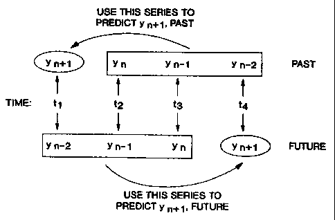
Figure 3 depicts a time series (times t1, t" t;,
and t,), and two corresponding series of measurements
taken in this time series (yn_~, y"_1 and y") , and (y", Yn.1
30 and y"_2) which are respectively used to predict future
or past measurements of the variable y at a time n+1
using the method of the invention.
8
CA 02330629 2000-10-26
WO 99/58973 PCT/US99/10377
Figures 4, 5, and 6 depict experimental
iontophoretic flux data compared with predicted values
obtained using the method of the invention.
Figure 7 is an expanded pictorial representation of
components comprising one embodiment of an automatic
sampling system for use in the practice of the present
invention.
Figure 8 is a representation of one embodiment of a
bimodal electrode design. The figure presents an
overhead and schematic view of the electrode assembly
83. In the figure, the bimodal electrode is shown at 80
and can be, for example, a Ag/AgCl iontophoretic/counter
electrode. The sensing or working electrode (made from,
for example, platinum? is shown at 81. The reference
electrode is shown at 82 and can be, for example, a
Ag/AgCl electrode. The components are mounted on a
nonconductive substrate 84, for example, plastic or
ceramic. The conductive leads 87 leading to the
connection pad 85 are covered by a second nonconductive
piece 86 of similar or different material. In this
example of such an electrode the working electrode area
is approximately 1.35 cm2. The dashed line in Figure 8
represents the plane of the cross-sectional schematic
view presented in Figure 9.
Figure 9 is a representation of a cross-sectional
schematic view of the bimodal electrodes as they may be
used in conjunction with a reference electrode and a
hydrogel pad. In the figure, the components are as
follows: bimodal electrodes 90 and 91; sensing
electrodes 92 and 93; reference electrodes 94 and 95; a
substrate 96; and hydrogel pads 97 and 98.
9
CA 02330629 2000-10-26
WO 99/58973 PCT/US99/10377
Detailed Description of the Preferred Embodiments
Before describing the present invention in detail,
it is to be understood that this invention is not
limited to particular compositions or biological systems
as such may, of course, vary. It is also to be
understood that the terminology used herein is for the
purpose of describing particular embodiments only, and
is not intended to be limiting.
As used in this specification and the appended
claims, the singular forms "a", "an" and "the" include
plural referents unless the content clearly dictates
otherwise. Thus, for example, reference to "an analyte"
includes mixtures of analytes, and the like.
Unless defined otherwise, all technical and
scientific terms used herein have the same meaning as
commonly understood by one of ordinary skill in the art
to which the invention pertains. Although any methods
and materials similar or equivalent to those described
herein can be used in the practice for testing of the
present invention, the preferred materials and methods
are described herein.
In describing and claiming the present invention,
the following terminology will be used in accordance
with the definitions set out below.
Definitions
The terms "analyte" and "target analyte" are used
herein to denote any physiological analyte of interest
that is a specific substance or component that is being
detected and/or measured in a chemical, physical,
enzymatic, or optical analysis. A detectable signal
(e.g., a chemical signal or electrochemical signal) can
CA 02330629 2000-10-26
WO 99/58973 PCTNS99/10377
be obtained, either directly or indirectly, from such an
analyte or derivatives thereof. Furthermore, the terms
"analyte" and "substance" are used interchangeably
herein, and are intended to have the same meaning, and
thus encompass any substance of interest. In preferred
embodiments, the analyte is a physiological analyte of
interest, for example, glucose, or a chemical that has a
physiological action, for example, a drug or
pharmacological agent.
A "sampling device" or "sampling system" refers to
any device for obtaining a sample from a biological
system for the purpose of determining the concentration
of an analyte of interest. As used herein, the term
"sampling" means invasive, minimally invasive or non-
invasive extraction of a substance from the biological
system, generally across a membrane such as skin or
mucosa. The membrane can be natural or artificial, and
can be of plant or animal nature, such as natural or
artificial skin, blood vessel tissue, intestinal tissue,
and the like. Typically, the sampling means are in
operative contact with a "reservoir," or "collection
reservoir," wherein the sampling means is used for
extracting the analyte from the biological system into
the reservoir to obtain the analyte in the reservoir. A
"biological system" includes both living and
artificially maintained systems. Examples of minimally
invasive and noninvasive sampling techniques include
iontophoresis, sonophoresis, suction, electroporation,
thermal poration, passive diffusion, microfine
(miniature) lances or cannulas, subcutaneous implants or
insertions, and laser devices. Sonophoresis uses
ultrasound to increase the permeability of the skin
11
CA 02330629 2000-10-26
WO 99/58973 PCT/US99/10377
(see, e.g., Menon et al. (1994) Skin Pharmacology 7:130-
139). Suitable sonophoresis sampling systems are
described in International Publication No. WO 91/12772,
published 5 September 1991. Passive diffusion sampling
devices are described, for example, in International
Publication Nos.: WO 97/38126 (published 16 October
1997); WO 97/42888, WO 97/42886, WO 97/42885, and WO
97/42882 (all published 20 November 1997); and WO
97/43962 (published 27 November 1997). Laser devices
use a small laser beam to burn a hole through the upper
layer of the patient's skin (see, e.g., Jacques et al.
(1978) J. Invest. Dermatology 88:88-93). Examples of
invasive sampling techniques include traditional needle
and syringe or vacuum sample tube devices.
The term "collection reservoir" is used to describe
any suitable containment means for containing a sample
extracted from a biological system. For example, the
collection reservoir can be a receptacle containing a
material which is sonically conductive (e. g., water with
ions therein), or alternatively, it can be a material,
such as, a sponge-like material or hydrophilic polymer,
used to keep the water in place. Such collection
reservoirs can be in the form of a hydrogel (for
example, in the form of a disk or pad). Hydrogels are
typically referred to as "collection inserts." Other
suitable collection reservoirs include, but are not
limited to, tubes, vials, capillary collection devices,
cannulas, and miniaturized etched, ablated or molded
flow paths.
A "housing" for the sampling system can further
include suitable electronics (e. g., microprocessor,
memory, display and other circuit components) and power
12
CA 02330629 2000-10-26
WO 99/58973 PCT/US99/10377
sources for operating the sampling system in an
automatic fashion.
A "monitoring system," as used herein, refers to a
system useful for continually or continuously measuring
a physiological analyte present in a biological system.
Such a system typically includes, but is not limited to,
sampling means, sensing means, and a microprocessor
means in operative communication with the sampling means
and the sensing means.
The term "artificial," as used herein, refers to an
aggregation of cells of monolayer thickness or greater
which are grown or cultured in vivo or in vitro, and
which function as a tissue of an organism but are not
actually derived, or excised, from a pre-existing source
or host.
The term "subject" encompasses any warm-blooded
animal, particularly including a member of the class
Mammalia such as, without limitation, humans and
nonhuman primates such as chimpanzees and other apes and
monkey species; farm animals such as cattle, sheep,
pigs, goats and horses; domestic mammals such as dogs
and cats; laboratory animals including rodents such as
mice, rats and guinea pigs, and the like. The term does
not denote a particular age or sex. Thus, adult and
newborn subjects, as well as fetuses, whether male or
female, are intended to be covered.
As used herein, the term "continual measurement"
intends a series of two or more measurements obtained
from a particular biological system, which measurements
are obtained using a single device maintained in
operative contact with the biological system over the
time period in which the series of measurements is
obtained. The term thus includes continuous
13
CA 02330629 2000-10-26
WO 99/58973 PCT/US99/10377
measurements.
The term "transdermal," as used herein, includes
both transdermal and transmucosal techniques, i.e.,
extraction of a target analyte across skin or mucosal
tissue. Aspects of the invention which are described
herein in the context of "transdermal," unless otherwise
specified, are meant to apply to both transdermal and
transmucosal techniques.
The term "transdermal extraction," or
"transdermally extracted" intends any noninvasive, or at
least minimally invasive sampling method, which entails
extracting and/or transporting an analyte from beneath a
tissue surface across skin or mucosal tissue. The term
thus includes extraction of an analyte using
iontophoresis (reverse iontophoresis), electroosmosis,
sonophoresis, microdialysis, suction, and passive
diffusion. These methods can, of course, be coupled
with application of skin penetration enhancers or skin
permeability enhancing technique such as tape stripping
or pricking with micro-needles. The term "transdermally
extracted" also encompasses extraction techniques which
employ thermal poration, electroporation, microfine
lances, microfine canulas, subcutaneous implants or
insertions, and the like.
The term "iontophoresis" intends a method for
transporting substances across tissue by way of an
application of electrical energy to the tissue. In
conventional iontophoresis, a reservoir is provided at
the tissue surface to serve as a container of material
to be transported. Iontophoresis can be carried out
using standard methods known to those of skill in the
art, for example, by establishing an electrical
potential using a direct current (DC) between fixed
14
CA 02330629 2000-10-26
WO 99/58973 PCT/US99/10377
anode and cathode "iontophoretic electrodes,"
alternating a direct current between anode and cathode
iontophoretic electrodes, or using a more complex
waveform such as applying a current with alternating
polarity (AP) between iontophoretic electrodes (so that
each electrode is alternately an anode or a cathode).
The term "reverse iontophoresis" refers to the
movement of a substance from a biological fluid across a
membrane by way of an applied electric potential or
current. In reverse iontophoresis, a reservoir is
provided at the tissue surface to receive the extracted
material.
"Electroosmosis" refers to the movement of a
substance through a membrane by way of an electric
field-induced convective flow. The terms iontophoresis,
reverse iontophoresis, and electroosmosis, will be used
interchangeably herein to refer to movement of any
sonically charged or uncharged substance across a
membrane (e. g., an epithelial membrane) upon application
of an electric potential to the membrane through an
sonically conductive medium.
The term "sensing device," "sensing means," or
"biosensor device" encompasses any device that can be
used to measure the concentration of an analyte, or
derivative thereof, of interest. Preferred sensing
devices for detecting blood analytes generally include
electrochemical devices and chemical devices. Examples
of electrochemical devices include the Clark electrode .
system (see, e.g., Updike, et al., (1967) Nature
214:986-988), and other amperometric, coulometric, or
potentiometric electrochemical devices. Examples of
chemical devices include conventional enzyme-based
reactions as used in the Lifescan° glucose monitor
CA 02330629 2000-10-26
WO 99/58973 PCT/US99/10377
(Johnson and Johnson, New Brunswick, NJ) (see, e.g.,
U.S. Patent 4,935,346 to Phillips, et al.).
A "biosensor" or "biosensor device" includes, but
is not limited to, a "sensor element" which includes,
but is not limited to, a "biosensor electrode" or
"sensing electrode" or "working electrode" which refers
to the electrode that is monitored to determine the
amount of electrical signal at a point in time or over a
given time period, which signal is then correlated with
the concentration of a chemical compound. The sensing
electrode comprises a reactive surface which converts
the analyte, or a derivative thereof, to electrical
signal. The reactive surface can be comprised of any
electrically conductive material such as, but not
limited to, platinum-group metals (including, platinum,
palladium, rhodium, ruthenium, osmium, and iridium),
nickel, copper, silver, and carbon, as well as, oxides,
dioxides, combinations or alloys thereof. Some
catalytic materials, membranes, and fabrication
technologies suitable for the construction of
amperometric biosensors were described by Newman, J.D.,
et al.(Analytical Chemistry 67(24), 4594-4599, 1995).
The "sensor element" can include components in
addition to a biosensor electrode, for example, it can
include a "reference electrode," and a "counter
electrode." The term "reference electrode" is used
herein to mean an electrode that provides a reference
potential, e.9., a potential can be established between
a reference electrode and a working electrode. The term
"counter electrode" is used herein to mean an electrode
in an electrochemical circuit which acts as a current
source or sink to complete the electrochemical circuit.
Although it is not essential that a counter electrode be
16
CA 02330629 2000-10-26
WO 99/58973 PCT/US99110377
employed where a reference electrode is included in the
circuit and the electrode is capable of performing the
function of a counter electrode, it is preferred to have
separate counter and reference electrodes because the
reference potential provided by the reference electrode
is most stable when it is at equilibrium. If the
reference electrode is required to act further as a
counter electrode, the current flowing through the
reference electrode may disturb this equilibrium.
Consequently, separate electrodes functioning as counter
and reference electrodes are most preferred.
In one embodiment, the "counter electrode" of the
"sensor element" comprises a "bimodal electrode." The
term "bimodal electrode" as used herein typically refers
to an electrode which is capable of functioning non-
simultaneously as, for example, both the counter
electrode (of the "sensor element") and the
iontophoretic electrode (of the "sampling means").
The terms "reactive surface," and "reactive face"
are used interchangeably herein to mean the surface of
the sensing electrode that: (1) is in contact with the
surface of an electrolyte containing material (e. g. gel)
which contains an analyte or through which an analyte,
or a derivative thereof, flows from a source thereof;
(2) is comprised of a catalytic material (e. g., carbon,
platinum, palladium, rhodium, ruthenium, or nickel
and/or oxides, dioxides and combinations or alloys
thereof) or a material that provides sites for
electrochemical reaction; (3) converts a chemical signal
(e. g. hydrogen peroxide) into an electrical signal
(e.g., an electrical current); and (4) defines the
electrode surface area that, when composed of a reactive
material, is sufficient to drive the electrochemical
17
CA 02330629 2000-10-26
WO 99/58973 PCT/US99/10377
reaction at a rate sufficient to generate a detectable,
reproducibly measurable, electrical signal that is
correlatable with the amount of analyte present in the
electrolyte.
S The term "collection reservoir" and "collection
insert" are used to describe any suitable containment
means for containing a sample extracted from a
biological system. The reservoir can include a material
which is sonically conductive (e. g., water with ions
therein), wherein another material such as a sponge-like
material or hydrophilic polymer is used to keep the
water in place. Such collection reservoirs can be in
the form of a hydrogel (for example, in the shape of a
disk or pad). Other suitable collection reservoirs
include, but are not limited to, tubes, vials, capillary
collection devices, cannulas, and miniaturized etched,
ablated or molded flow paths.
An "sonically conductive material" refers to any
material that provides ionic conductivity, and through
which electrochemically active species can diffuse. The
sonically conductive material can be, for example, a
solid, liquid, or semi-solid (e.g., in the form of a
gel) material that contains an electrolyte, which can be
composed primarily of water and ions (e. g., sodium
chloride), and generally comprises 50% or more water by
weight. The material can be in the form of a gel, a
sponge or pad (e. g., soaked with an electrolytic
solution), or any other material that can contain an
electrolyte and allow passage therethrough of
electrochemically active species, especially the analyte
of interest.
The term "physiological effect" encompasses effects
produced in the subject that achieve the intended
18
CA 02330629 2000-10-26
WO 99/58973 PCT/US99/10377
purpose of a therapy. In preferred embodiments, a
physiological effect means that the symptoms of the
subject being treated are prevented or alleviated. For
example, a physiological effect would be one that
results in the prolongation of survival in a patient.
A "laminate" , as used herein, refers to structures
comprised of at least two bonded layers. The layers may
be bonded by welding or through the use of adhesives.
Examples of welding include, but are not limited to, the
following: ultrasonic welding, heat bonding, and
inductively coupled localized heating followed by
localized flow. Examples of common adhesives include,
but are not limited to, pressure sensitive adhesives,
thermoset adhesives, cyanocrylate adhesives, epoxies,
contact adhesives, and heat sensitive adhesives.
A "collection assembly", as used herein, refers to
structures comprised of several layers, where the
assembly includes at least one collection insert, for
example a hydrogel. An example of a collection assembly
of the present invention is a mask layer, collection
inserts, and a retaining layer where the layers are held
in appropriate, functional relationship to each other
but are not necessarily a laminate, i.e., the layers may
not be bonded together. The layers may, for example, be
held together by interlocking geometry or friction.
An "autosensor assembly", as used herein, refers to
structures generally comprising a mask layer, collection
inserts, a retaining layer, an electrode assembly, and a
support tray. The autosensor assembly may also include
liners. The layers of the assembly are held in
appropriate, functional relationship to each other.
The mask and retaining layers are preferably
composed of materials that are substantially impermeable
19
CA 02330629 2000-10-26
WO 99/58973 PCT/US99/10377
to the analyte (chemical signal) to be detected (e. g.,
glucose); however, the material can be permeable to
other substances. By "substantially impermeable" is
meant that the material reduces or eliminates chemical
signal transport (e.g., by diffusion). The material can
allow for a low level of chemical signal transport, with
the proviso that chemical signal that passes through the
material does not cause significant edge effects at the
sensing electrode.
"Substantially planar" as used herein, includes a
planar surface that contacts a slightly curved surface,
for example, a forearm or upper arm of a subject. A
"substantially planar" surface is, for example, a
surface having a shape to which skin can conform, i.e.,
contacting contact between the skin and the surface.
By the term "printed" as used herein is meant a
substantially uniform deposition of an electrode
formulation onto one surface of a substrate (i.e., the
base support). It will be appreciated by those skilled
in the art that a variety of techniques may be used to
effect substantially uniform deposition of a material
onto a substrate, e.g., Gravure-type printing, extrusion
coating, screen coating, spraying, painting, or the
like.
The term "Taylor Series Exponential Smoothing
Function ("TSES")" encompasses mathematical functions
(algorithms) for predicting the behavior of a variable
at a different point in time, which factors in the
slope, and the rate of change of the slope. An example
of a TSES function useful in connection with the present
invention is a TSES function represented by:
_ _a2
yn+ 1 - yn + a (.Yn yn-1 ) + 2 (yn ~.Yn-1 + .Yn-2
CA 02330629 2000-10-26
WO 99/58973 PCT/US99/10377
wherein: a is an optimizable variable which is a real
number of between 0 and 1, and is adjusted based on the
particular measurements obtained and the relationship
between those measurements and actual results; n is an
evenly spaced time interval; and y is an analyte
concentration or signal converted to an analyte
concentration which signal measurement is optimized to
fit the results sought, e.g., to correspond with a
reference analyte concentration.
A "future time point" refers to the time point in
the future at which the concentration of the analyte of
interest is predicted. In preferred embodiments, this
term refers to a time point that is one time interval
ahead, where a time interval is the amount of time
between sampling and sensing events.
General Methods
The present invention relates to use of a sensing
device for measuring the concentration of a target
analyte present in a biological system. In preferred
embodiments, the sensing device comprises a biosensor.
In other preferred embodiments, a sampling device is
used to extract small amounts of a target analyte from
the biological system, and then sense and/or quantify
the concentration of the target analyte. Measurement
with the biosensor and/or sampling with the sampling
device can be carried out in a continual manner.
Continual measurement allows for closer monitoring of
target analyte concentration fluctuations.
The analyte can be any specific substance or
component that one is desirous of detecting and/or
measuring in a chemical, physical, enzymatic, or optical
21
CA 02330629 2000-10-26
WO 99/58973 PCT/US99/10377
analysis. Such analytes include, but are not limited
to, amino acids, enzyme substrates or products
indicating a disease state or condition, other markers
of disease states or conditions, drugs of abuse,
therapeutic and/or pharmacologic agents (e. g.,
theophylline, anti-HIV drugs, lithium, anti-epileptic
drugs, cyclosporin, chemotherapeutics), electrolytes,
physiological analytes of interest (e. g., urate/uric
acid, carbonate, calcium, potassium, sodium, chloride,
bicarbonate (C02), glucose, urea (blood urea nitrogen),
lactate/lactic acid, hydroxybutyrate, cholesterol,
triglycerides, creatine, creatinine, insulin,
hematocrit, and hemoglobin), blood gases (carbon
dioxide, oxygen, pH), lipids, heavy metals (e. g., lead,
copper), and the like. In preferred embodiments, the
analyte is a physiological analyte of interest, for
example glucose, or a chemical that has a physiological
action, for example a drug or pharmacological agent.
In order to facilitate detection of the analyte, an
enzyme can be disposed in the collection reservoir, or,
if several collection reservoirs are used, the enzyme
can be disposed in several or all of the reservoirs.
The selected enzyme is capable of catalyzing a reaction
with the extracted analyte (in this case glucose) to the
extent that a product of this reaction can be sensed,
e.g.; can be detected electrochemically from the
generation of a current which current is detectable and
proportional to the concentration or amount of the
analyte which is reacted. A suitable enzyme is glucose
oxidase which oxidizes glucose to gluconic acid and
hydrogen peroxide. The subsequent detection of hydrogen
peroxide on an appropriate biosensor electrode generates
22
CA 02330629 2000-10-26
WO 99/58973 PCT/US99/10377
two electrons per hydrogen peroxide molecule which
create a current which can be detected and related to
the amount of glucose entering the device. Glucose
oxidase (GOx) is readily available commercially and has
well known catalytic characteristics. However, other
enzymes can also be used, so long as they specifically
catalyze a reaction with an analyte or substance of
interest to generate a detectable product in proportion
to the amount of analyte so reacted.
In like manner, a number of other analyte-specific
enzyme systems can be used in the invention, which
enzyme systems operate on much the same general
techniques. For example, a biosensor electrode that
detects hydrogen peroxide can be used to detect ethanol
using an alcohol oxidase enzyme system, or similarly
uric acid with urate oxidase system, urea with a urease
system, cholesterol with a cholesterol oxidase system,
and theophylline with a xanthine oxidase system.
In addition, the oxidase enzyme (used for hydrogen
peroxidase-based detection) can be replaced with another
redox system, for example, the dehydrogenase-enzyme NAD-
NADH, which offers a separate route to detecting
additional analytes. Dehydrogenase-based sensors can
use working electrodes made of gold or carbon (via
mediated chemistry). Examples of analytes suitable for
this type of monitoring include, but are not limited to,
cholesterol, ethanol, hydroxybutyrate, phenylalanine,
triglycerides, and urea. Further, the enzyme can be
eliminated and detection can rely on direct
electrochemical or potentiometric detection of an
analyte. Such analytes include, without limitation,
heavy metals (e. g., cobalt, iron, lead, nickel, zinc),
23
CA 02330629 2000-10-26
WO 99/58973 PCT/US99/10377
oxygen, carbonate/carbon dioxide, chloride, fluoride,
lithium, pH, potassium, sodium, and urea. Also, the
sampling system described herein can be used for
therapeutic drug monitoring, for example, monitoring
anti-epileptic drugs (e. g., phenytion), chemotherapy
(e.g., adriamycin), hyperactivity (e.g., ritalin), and
anti-organ-rejection (e. g., cyclosporin).
In the general method of the invention, a raw
signal is obtained from a sensing device, which signal
is related to a target analyte present in the biological
system. The raw signal can be obtained using any
suitable sensing methodology including, for example,
methods which rely on direct contact of a sensing
apparatus with the biological system; methods which
extract samples from the biological system by invasive,
minimally invasive, and non-invasive sampling
techniques, wherein the sensing apparatus is contacted
with the extracted sample; methods which rely on
indirect contact of a sensing apparatus with the
biological system; and the like. In preferred
embodiments of the invention, methods are used to
extract samples from the biological sample using
minimally invasive or non-invasive sampling techniques.
The sensing apparatus used with any of the above-noted
methods can employ any suitable sensing element to
provide the signal including, but not limited to,
physical, chemical, electrochemical, photochemical,
spectrophotometric, polarimetric, colorimetric,
radiometric, or like elements. In preferred embodiments
of the invention, a biosensor is used which comprises an
electrochemical sensing element.
In another embodiment of the invention, a near-IR
24
CA 02330629 2000-10-26
WO 99/58973 PCT/US99/10377
glucose sensing apparatus is used to detect blood
glucose in a subject, and thus generate the raw signal.
A number of near-IR glucose sensing devices suitable for
use in the present method are known in the art and are
readily available. For example, a near-IR radiation
diffuse-reflection laser spectroscopy device is
described in U.S. Patent No. 5,267,152 to Yang et al.
Similar near-IR spectrometric devices are also described
in U.S. Patent No. 5,086,229 to Rosenthal et al. and
U.S. Patent No. 4,975,581 to Robinson et al. These
near-IR devices use traditional methods of reflective or
transmissive near infrared (near-IR) analysis to measure
absorbance at one or more glucose-specific wavelengths,
and can be contacted with the subject at an appropriate
location, such as a finger-tip, skin fold, eyelid, or
forearm surface to obtain the raw signal.
The raw signal obtained using any of the above-
described methodologies is then converted into an
analyte-specific value of known units to provide an
interpretation of the signal obtained from the sensing
device. The interpretation uses a mathematical
transformation to model the relationship between a
measured response in the sensing device and a
corresponding analyte-specific value. Thus, a
calibration step is used herein to relate, for example,
an electrochemical signal (detected by a biosensor), or
near-IR absorbance spectra (detected with a near-IR
detector) with the concentration of a target analyte in
a biological system.
Analyte-specific values are then used to predict
future (time forecasting) or past (calibration)
measurements of the target analyte concentration in the
CA 02330629 2000-10-26
WO 99/58973 PCT/US99/10377
biological system. More particularly, a series of
analyte-specific values are obtained, and this
measurement series is then used to predict unmeasured
analyte values at different points in time, e.g., future
or past time points. In this manner, lag times inherent
in certain sampling and/or sensing techniques can be
eliminated to provide real-time measurement predictions.
The predicted analyte values can optionally be used
in a subsequent step to control an aspect of the
biological system. In one embodiment, predicted analyte
values are used to determine when, and at what level, a
constituent should be added to the biological system in
order to control an aspect of the biological system. In
a preferred embodiment, the analyte value can be used in
a feedback control loop to control a physiological
effect in the biological system.
The above general methods can, of course, be used
with a wide variety of biological systems, target
analytes, and/or sensing techniques. The determination
of particularly suitable combinations is within the
skill of the ordinarily skilled artisan when directed by
the instant disclosure. Although these methods are
broadly applicable to measuring any chemical analyte
and/or substance in a biological system, the invention
is expressly exemplified for use in a non-invasive,
transdermal sampling system which uses an
electrochemical biosensor to quantify or qualify glucose
or a glucose metabolite.
Obtaining the raw signal.
The raw signal can be obtained using any sensing
device that is operatively contacted with the biological
26
CA 02330629 2000-10-26
WO 99/58973 PCT/US99/10377
system. Such sensing devices can employ physical,
chemical, electrochemical, spectrophotometric,
polarimetric, colorimetric, radiometric, or like
measurement techniques. In addition, the sensing device
can be in direct or indirect contact with the biological
system, or used with a sampling device which extracts
samples from the biological system using invasive,
minimally invasive or non-invasive sampling techniques.
In preferred embodiments, a minimally invasive or non-
invasive sampling device is used to obtain samples from
the biological system, and the sensing device comprises
a biosensor with an electrochemical sensing element. In
particularly preferred embodiments, a sampling device is
used to obtain continual transdermal or transmucosal
samples from a biological system, and the analyte of
interest is glucose.
More specifically, a non-invasive glucose
monitoring device is used to measure changes in glucose
levels in an animal subject over a wide range of glucose
concentrations. The sampling method is based on
transdermal glucose extraction and the sensing method is
based on electrochemical detection technology. The
device can be contacted with the biological system
continuously, and automatically obtains glucose samples
in order to measure glucose concentration at
preprogrammed intervals.
Sampling is carried out continually by non
invasively extracting glucose through the skin of the
patient using an iontophoretic current. More
particularly, an iontophoretic current is applied to a
surface of the skin of a subject. When the current is
applied, ions or charged molecules pull along other
27
CA 02330629 2000-10-26
WO 99/58973 PCT/US99I10377
uncharged molecules or particles such as glucose which
are drawn into a collection reservoir placed on the
surface of the skin. The collection reservoir may
comprise any sonically conductive material and is
preferably in the form of a hydrogel which is comprised
of a hydrophilic material, water and an electrolyte.
The collection reservoir may further contain an enzyme
which catalyzes a reaction between glucose and oxygen.
The enzyme is preferably glucose oxidase (GOx) which
catalyzes the reaction between glucose and oxygen and
results in the production of hydrogen peroxide. The
hydrogen peroxide reacts at a catalytic surface of a
biosensor electrode, resulting in the generation of
electrons which create a detectable biosensor current
(raw signal). Based on the amount of biosensor current
created over a given period of time, a measurement is
taken, which measurement is related to the amount of
glucose drawn into the collection reservoir over a given
period of time. In a preferred embodiment the reaction
is allowed to continue until substantially all of the
glucose in the collection reservoir has been subjected
to a reaction and is therefore no longer detectable, and
the total biosensor current generated is related to the
concentration of glucose in the subject.
When the reaction is complete, the process is
repeated and a subsequent measurement is obtained. More
specifically, the iontophoretic current is again
applied, glucose is drawn through the skin surface into
the collection reservoir, and the reaction is catalyzed
in order to create a biosensor current. These sampling
(extraction) and sensing operations are integrated such
that glucose from interstitial fluid directly beneath
28
CA 02330629 2000-10-26
WO 99/58973 PCT/US99/10377
the skin surface is extracted into the hydrogel
collection pad where it contacts the GOx enzyme. The
GOx enzyme converts glucose and oxygen in the hydrogel
to hydrogen peroxide which diffuses to a Pt-based sensor
and reacts with the sensor to regenerate oxygen and form
electrons. The electrons generate an electrical signal
that can be measured, analyzed, and correlated to blood
glucose.
A generalized method for continual monitoring of a
physiological analyte is disclosed in International
Publication No. WO 97/24059, published 10 July 1997. As
noted in that publication, the analyte is extracted into
a reservoir containing a hydrogel which is preferably
comprised of a hydrophilic material of the type
described in International Publication No. WO 97/02811,
published 30 January 1997. Suitable hydrogel materials
include polyethylene oxide polyacrylic acid,
polyvinylalcohol and related hydrophilic polymeric
materials combined with water to form an aqueous gel.
In the above non-invasive glucose monitoring
device, a biosensor electrode is positioned on a surface
of the hydrogel opposite the surface contacting the
skin. The sensor electrode acts as a detector which
detects current generated by hydrogen peroxide in the
redox reaction, or more specifically detects current
which is generated by the electrons generated by the
redox reaction catalyzed by the platinum surface of the
electrode. The details of such electrode assemblies and
devices for iontophoretic extraction of glucose are
disclosed in International Publication No. WO 96/00110,
published 4 January 1996, and International Publication
No. WO 97/10499, published 2 March 1997.
29
CA 02330629 2000-10-26
WO 99/58973 PCT/US99/10377
Referring now to Figures 1A and 1B, an
iontophoretic collection reservoir and electrode
assembly for use in a transdermal sensing device is
generally indicated at 2. The assembly comprises two
iontophoretic collection reservoirs, 4 and 6, each
having a conductive medium 8, and 10 (preferably
cylindrical hydrogel pads), respectively disposed
therein. First (12) and second (14) ring-shaped
iontophoretic electrodes are respectively contacted with
conductive medium 8 and 10. The first iontophoretic
electrode 12 surrounds three biosensor electrodes which
are also contacted with the conductive medium 8, a
working electrode 16, a reference electrode 18, and a
counter electrode 20. A guard ring 22 separates the
biosensor electrodes from the iontophoretic electrode 12
to minimize noise from the iontophoretic circuit.
Conductive contacts provide communication between the
electrodes and an associated power source and control
means as described in detail below. A similar biosensor
electrode arrangement can be contacted with the
conductive medium 10, or the medium can not have a
sensor means contacted therewith.
Referring now to Figure 2, the iontophoretic
collection reservoir and electrode assembly 2 of Figures
1A and 1B is shown in exploded view in combination with
a suitable iontophoretic sampling device housing 32.
The housing can be a plastic case or other suitable
structure which preferably is configured to be worn on a
subjects arm in a manner similar to a wrist watch. As
can be seen, conductive media 8 and 10 (hydrogel pads)
are separable from the assembly 2; however, when the
CA 02330629 2000-10-26
WO 99!58973 PCT/US99/10377
assembly 2 and the housing 32 are assembled to provide
an operational iontophoretic sampling device 30, the
media are in contact with the electrodes to provide a
electrical contact therewith.
Referring now to Figure 7, an exploded view of the
key components from an embodiment of an iontophoretic
sampling system is presented. The sampling system
components include two biosensor/iontophoretic electrode
assemblies, 704 and 706, each of which have an annular
iontophoretic electrode, respectively indicated at 708
and 710, which encircles a biosensor 712 and 714. The
electrode assemblies 704 and 706 are printed onto a
polymeric substrate 716 which is maintained within a
sensor tray 718. A collection reservoir assembly 720 is
arranged over the electrode assemblies, wherein the
collection reservoir assembly comprises two hydrogel
inserts 722 and 724 retained by a gel retaining layer
726 and a mask layer 728.
In one embodiment, the electrode assemblies can
include bimodal electrodes as shown in Figure 8 and
described below.
The components shown in exploded view in Figure 7
are intended for use in an automatic sampling device
which is configured to be worn like an ordinary
wristwatch. As described in International Publication
No. WO 96/00110, published 4 January 1996, the
wristwatch housing (not shown) contains conductive leads
which communicate with the iontophoretic electrodes and
the biosensor electrodes to control cycling and provide
power to the iontophoretic electrodes, and to detect
electrochemical signals produced at the biosensor
electrode surfaces. The wristwatch housing can further
include suitable electronics (e. g., microprocessor,
31
CA 02330629 2000-10-26
WO 99/58973 PCT/US99/10377
memory, display and other circuit components) and power
sources for operating the automatic sampling system.
Modifications and additions to the embodiment of
Figure 7 will be apparent to those skilled in the art in
light of the teachings of the present specification.
A power source (e.g., one or more rechargeable or
nonrechargeable batteries) can be disposed within the
housing 32 or within the straps 34 which hold the device
in contact with a skin or mucosal surface of a subject.
In use, an electric potential (either direct current or
a more complex waveform) is applied between the two
iontophoretic electrodes 12 and 14 such that current
flows from the first iontophoretic electrode 12, through
the first conductive medium 8 into the skin or mucosal
surface, and then back out through the second conductive
medium 10 to the second iontophoretic electrode I4. The
current flow is sufficient to extract substances
including an analyte of interest through the skin into
one or both of collection reservoirs 4 and 6. The
electric potential may be applied using any suitable
technique, for example, the applied current density may
be in the range of about 0.01 to 0.5 mA/cm2. In a
preferred embodiment, the device is used for continual
or continuous monitoring, and the polarity of
iontophoretic electrodes 12 and 14 is alternated at a
rate of about one switch every 10 seconds to about one
switch every hour so that each electrode is alternately
a cathode or an anode. The housing 32 can further
include an optional temperature sensing element (e.g., a
thermistor, thermometer, or thermocouple device) which
monitors the temperature at the collection reservoirs to
enable temperature correction of sensor signals. The
32
CA 02330629 2000-10-26
WO 99/58973 PCTNS99/10377
housing can also include an optional conductance sensing
element (e. g., an integrated pair of electrodes) which
monitors conductance at the skin or mucosal surface to
enable data screening correction or invalidation of
sensor signals.
In a further aspect, the sampling device can
operate in an alternating polarity mode using first and
second bimodal electrodes (Figure 9, 90 and 91) and two
collection reservoirs (Figure 9, 97 and 98). Each bi-
modal electrode (Figure 8, 80; Figure 9, 90 and 91)
serves two functions depending on the phase of the
operation: (1) an electro-osmotic electrode (or
iontophoretic electrode) used to electrically draw
analyte from a source into a collection reservoir
comprising water and an electrolyte, and to the area of
the electrode subassembly; and (2) as a counter
electrode to the first sensing electrode at which the
chemical compound is catalytically converted at the face
of the sensing electrode to produce an electrical
signal.
The reference (Figure 9, 94 and 95; Figure 8, 82)
and sensing electrodes (Figure 9, 92 and 93; Figure 8,
81), as well as, the bimodal electrode (Figure 9, 90 and
91; Figure 8, 80) are connected to a standard
potentiostat circuit during sensing. In general,
practical limitations of the system require that the
bimodal electrode will not act as both a counter and
iontophoretic electrode simultaneously.
The general operation of an iontophoretic sampling
system in this embodiment is the cyclical repetition of
two phases: (1) a reverse-iontophoretic phase, followed
by a (2) sensing phase. During the reverse
iontophoretic phase, the first bimodal electrode (Figure
33
CA 02330629 2000-10-26
WO 99/58973 PCTNS99/10377
9, 90) acts as an iontophoretic cathode and the second
bimodal electrode (Figure 9, 91) acts as an
iontophoretic anode to complete the circuit. Analyte is
collected in the reservoirs, for example, a hydrogel
(Figure 9, 97 and 98). At the end of the reverse
iontophoretic phase, the iontophoretic current is turned
off. During the sensing phase, in the case of glucose,
a potential is applied between the reference electrode
(Figure 9, 94) and the sensing electrode (Figure 9, 92).
The chemical signal reacts catalytically on the
catalytic face of the first sensing electrode (Figure 9,
92) producing an electrical current, while the first bi-
modal electrode (Figure 9, 90) acts as a counter
electrode to complete the electrical circuit.
The electrode described is particularly adapted for
use in conjunction with a hydrogel collection reservoir
system for monitoring glucose levels in a subject
through the reaction of collected glucose with the
enzyme glucose oxidase present in the hydrogel matrix.
The bi-modal electrode is preferably comprised of
Ag/AgCl. The electrochemical reaction which occurs at
the surface of this electrode serves as a facile source
or sink for electrical current. This property is
especially important for the iontophoresis function of
the electrode. Lacking this reaction, the iontophoresis
current could cause the hydrolysis of water to occur at
the iontophoresis electrodes causing pH changes and
possible gas bubble formation. The pH changes to acidic
or basic pH could cause skin irritation or burns. The
ability of an Ag/AgCl electrode to easily act as a
source of sink current is also an advantage for its
counter electrode function. For a three electrode
electrochemical cell to function properly, the current
34
CA 02330629 2000-10-26
WO 99/58973 PCT/US99/10377
generation capacity of the counter electrode should not
limit the speed of the reaction at the sensing
electrode. In the case of a large sensing electrode,
the counter electrode should be able to source
proportionately larger currents.
The design of the sampling system provides for a
larger sensing electrode (see for example, Figure 8)
than previously designed. Consequently, the size of the
bimodal electrode should be sufficient so that when
acting as a counter electrode with respect to the
sensing electrode the counter electrode does not become
limiting the rate of catalytic reaction at the sensing
electrode catalytic surface.
Two methods exist to ensure that the counter
electrode does not limit the current at the sensing
electrode: (1) the bi-modal electrode is made much
larger than the sensing electrode, or (2) a facile
counter reaction is provided.
During the reverse iontophoretic phase, the power
source provides a current. flow to the first bi-modal
electrode to facilitate the extraction of the chemical
signal into the reservoir. During the sensing phase,
the power source is used to provide voltage to the first
sensing electrode to drive the conversion of chemical
signal retained in reservoir to electrical signal at the
catalytic face of the sensing electrode. The power
source also maintains a fixed potential at the electrode
where, for example hydrogen peroxide is converted to
molecular oxygen, hydrogen ions, and electrons, which is
compared with the potential of the reference electrode
during the sensing phase. While one sensing electrode
is operating in the sensing mode it is electrically
connected to the adjacent bimodal electrode which acts
CA 02330629 2000-10-26
WO 99/58973 PCT/US99/10377
as a counter electrode at which electrons generated at
the sensing electrode are consumed.
The electrode sub-assembly can be operated by
electrically connecting the bimodal electrodes such that
each electrode is capable of functioning as both an
iontophoretic electrode and counter electrode along with
appropriate sensing electrodes) and reference
electrode(s), to create standard potentiostat circuitry.
A potentiostat is an electrical circuit used in
electrochemical measurements in three electrode
electrochemical cells. A potential is applied between
the reference electrode and the sensing electrode. The
current generated at the sensing electrode flows through
circuitry to the counter electrode (i.e., no current
flows through the reference electrode to alter its
equilibrium potential). Two independent potentiostat
circuits can be used to operate the two biosensors. For
the purpose of the present sampling system, the
electrical current measured at the sensing electrode
subassembly is the current that is correlated with an
amount of chemical signal.
With regard to continual operation for extended
periods of time, Ag/AgCl electrodes are provided herein
which are capable of repeatedly forming a reversible
couple which operates without unwanted electrochemical
side reactions (which could give rise to changes in pH,
and liberation of hydrogen and oxygen due to water
hydrolysis). The Ag/AgCl electrodes of the present
sampling system are thus formulated to withstand
repeated cycles of current passage in the range of about
0.01 to 1.0 mA per cmz of electrode area. With regard to
high electrochemical purity, the Ag/AgCl components are
dispersed within a suitable polymer binder to provide an
36
CA 02330629 2000-10-26
WO 99/58973 PCTNS99/10377
electrode composition which is not susceptible to attack
(e. g., plasticization) by components in the collection
reservoir, e.g., the hydrogel composition. The
electrode compositions are also formulated using
analytical- or electronic-grade reagents and solvents,
and the polymer binder composition is selected to be
free of electrochemically active contaminants which
could diffuse to the biosensor to produce a background
current.
Since the Ag/AgCl iontophoretic electrodes must be
capable of continual cycling over extended periods of
time, the absolute amounts of Ag and AgCl available in
the electrodes, and the overall Ag/AgCl availability
ratio, can be adjusted to provide for the passage of
high amounts of charge. Although not limiting in the
sampling system described herein, the Ag/AgCl ratio can
approach unity. In order to operate within the
preferred system which uses a biosensor having a
geometric area of 0.1 to 3 cmz, the iontophoretic
electrodes are configured to provide an approximate
electrode area of 0.3 to 1.0 cmz, preferably about 0.85
cmz. These electrodes provide for reproducible, repeated
cycles of charge passage at current densities ranging
from about 0.01 to 1.0 mA/cm~ of electrode area. More
particularly, electrodes constructed according to the
above formulation parameters, and having an approximate
electrode area of 0.85 cm~, are capable of a reproducible
total charge passage (in both anodic and cathodic
directions) of 270 mC, at a current of about 0.3 mA
(current density of 0.35 mA/cm2) for 48 cycles in a 24
hour period.
Once formulated, the Ag/AgCl electrode composition
is affixed to a suitable rigid or flexible nonconductive
37
CA 02330629 2000-10-26
WO 99/58973 PCT/US99/10377
surface as described above with respect to the biosensor
electrode composition. A silver (Ag) underlayer is
first applied to the surface in order to provide uniform
conduction. The Ag/AgCl electrode composition is then
applied over the Ag underlayer in any suitable pattern
or geometry using various thin film techniques, such as
sputtering, evaporation, vapor phase deposition, or the
like, or using various thick film techniques, such as
film laminating, electroplating, or the like.
Alternatively, the Ag/AgCl composition can be applied
using screen printing, pad printing, inkjet methods,
transfer roll printing, or similar techniques.
Preferably, both the Ag underlayer and the Ag/AgCl
electrode are applied using a low temperature screen
print onto a polymeric substrate. This low temperature
screen print can be carried out at about 125 to 160°C,
and the screening can be carried out using a suitable
mesh, ranging from about 100-400 mesh.
After a suitable iontophoretic extraction period,
one or both of the sensor electrode sets can be
activated in order to detect extracted substances
including the analyte of interest. Operation of the
iontophoretic sampling device 30 can be controlled by a
controller 36 (e. g., a microprocessor), which interfaces
with the iontophoretic electrodes, the sensor
electrodes, the power supply, the optional temperature
and/or conductance sensing elements, a display and other
electronics. For example, the controller 36 can include
a programmable a controlled circuit source/sink drive
for driving the iontophoretic electrodes. Power and
reference voltage are provided to the sensor electrodes,
and signal amplifiers can be used to process the signal
from the working electrode or electrodes. In general,
38
CA 02330629 2000-10-26
WO 99/58973 PCT/US99/10377
the controller discontinues the iontophoretic current
drive during sensing periods. A sensor confidence loop
can be provided for continually monitoring the sampling
system to insure proper operations.
User control can be carried out using push buttons
located on the housing 32, and an optional liquid
crystal display (LCD) can provide visual prompts,
readouts and visual alarm indications. The
microprocessor generally uses a series of program
sequences to control the operations of the sampling
device, which program sequences can be stored in the
microprocessor's read only memory (ROM). Embedded
software (firmware) controls activation of measurement
and display operations, calibration of analyte readings,
setting and display of high and low analyte value
alarms, display and setting of time and date functions,
alarm time, and display of stored readings. Sensor
signals obtained from the sensor electrodes can be
processed before storage and display by one or more
signal processing functions or algorithms which are
stored in the embedded software. The microprocessor can
also include an electronically erasable, programmable,
read only memory (EEPROM) for storing calibration
parameters, user settings and all downloadable
sequences. A serial communications port allows the
device to communicate with associated electronics, for
example, wherein the device is used in a feedback
control application to control a pump for delivery of a
medicament.
Converting to an analyte-specific value.
In one embodiment, one or more additional "active"
39
CA 02330629 2000-10-26
WO 99/58973 PCT/US99/10377
collection reservoirs (e.g., each containing the GOx
enzyme) can be used to obtain measurements, including
raw signal. In one embodiment, two active collection
reservoirs are used, and an average is taken between
signals from the reservoirs for each measurement time
point. Obtaining multiple signals, and then averaging
reads from each signals, allows for signal smoothing of
unusual data points from a sensor that otherwise may not
have been detected by data screening techniques.
Furthermore, skin site variability can be detected, and
"lag" and/or "lead" differences in blood glucose changes
relative to extracted glucose changes can be mitigated.
In another embodiment, a second collection reservoir can
be provided which serves as a blank (e.g., does not
contain the GOx enzyme). This second reservoir can
serve as an internal reference (blank) for the sensing
device, where a biosensor is used to measure the "blank"
signal from the reference reservoir which signal is then
used in a blank subtraction step as described below.
A generalized method for continual monitoring of a
physiological analyte is disclosed in International
Publication No. WO 97/24059, published 10 July 1997.
The raw signal is then converted into an analyte-
specific value using a calibration step which correlates
the signal obtained from the sensing device with the
concentration of the analyte present in the biological
system. A wide variety of calibration techniques can be
used to interpret such signals. These calibration
techniques apply mathematical, statistical and/or
pattern recognition techniques to the problem of signal
processing in chemical analyses, for example, using
neural networks, genetic algorithm signal processing,
CA 02330629 2000-10-26
WO 99/58973 PCT/US99/10377
linear regression, multiple-linear regression, or
principal components analysis of statistical (test)
measurements.
One method of calibration involves estimation
techniques. To calibrate an instrument using estimation
techniques, it is necessary to have a set of exemplary
measurements with known concentrations referred to as
the calibration set (e.g., reference set). This set
consists of m samples, each with n instrument variables
contained in an m by n matrix (X), and an m by 1 vector
(y), containing the concentrations. If a priori
information indicates the relationship between the
measurement and concentration is linear, the calibration
will attempt to determine an n by 1 transformation or
mapping (b), such that
y = Xb
is an optimal estimate of y according to a predefined
criteria. Numerous suitable estimation techniques
useful in the practice of the invention are known in the
art. These techniques can be used to provide
correlation factors (e. g., constants), which correlation
factors are then used in a mathematical transformation
to obtain a measurement value indicative of the
concentration of analyte present .in the biological
system at the times of measurement.
In one particular embodiment, the calibration step
can be carried out using artificial neural networks or
genetic algorithms. The structure of a particular
neural network algorithm used in the practice of the
invention can vary widely; however, the network should
contain an input layer, one or more hidden layers, and
one output layer. Such networks can be trained on a
41
CA 02330629 2000-10-26
WO 99/58973 PCT/US99/10377
test data set, and then applied to a population. There
are an infinite number of suitable network types,
transfer functions, training criteria, testing and
application methods which will occur to the ordinarily
skilled artisan upon reading the instant specification.
In particular embodiments of the present invention,
the detected current can be correlated with the
subject's blood glucose concentration (typically using
statistical algorithms associated with a microprocessor)
so that the system controller may display the subject's
actual blood glucose concentration as measured by the
sampling system. For example, the system can be
calibrated to the subject's actual blood glucose
concentration by sampling the subject's blood during a
standard glucose tolerance test, and analyzing the blood
glucose using both a standard blood glucose monitor and
the sampling system of the present invention. In
addition or alternately, the sampling system can be
calibrated at a calibration time point where the signal
obtained from the sampling system at that time point is
correlated to blood glucose concentration at that time
point as determined by direct blood testing (for
example, glucose concentration can be determined using a
HemoCue~ clinical analyzer (HemoCue AB, Sweden)). In
this manner, measurements obtained by the sampling
system can be correlated to actual values using known
statistical techniques. Such statistical techniques can
be formulated as algorithms) and incorporated in a
microprocessor associated with the sampling system.
In the context of the iontophoretic glucose
sampling device described hereinabove, a preferred
neural network algorithm could use, for example, the
42
CA 02330629 2000-10-26
WO 99/58973 PCT/US99/10377
following inputs to provide a blood glucose measurement:
time; signal from the active reservoir/signal from the
blank reservoir; signal from two active reservoirs
(averaged or cumulative); calibration time; skin
temperature; voltage; skin conductivity; and, when
operating in the training mode, measured glucose.
For example, perspiration contains glucose, and
perspiration occurring rapidly and in sufficient
quantities may affect the detected signal either before
or during biosensor measurement. Accordingly, a sensor
can be used to monitor perspiration levels for a given
measurement cycle at time points before, during, and/or
after iontophoresis, and before, during, and/or after
glucose sensing. Although a number of different
mechanisms can be used, skin conductance can be readily
measured with a device contacted with the skin. Skin
conductivity is related to perspiration.
In a similar manner, a sensor can be used to
measure skin temperature for a given measurement cycle
at time points before, during, and/or after
iontophoresis, and before, during, and/or after glucose
sensing.
Further, the sampling system can be pre-programmed
to begin execution of its signal measurements (or other
functions) at a designated time. One application of
this feature is to have the sampling system in contact
with a subject and to program the sampling system to
begin sequence execution during the night so that it is
available for calibration immediately upon waking. One
advantage of this feature is that it removes any need to
wait for the sampling system to warm-up before
calibrating it.
43
CA 02330629 2000-10-26
WO 99/58973 PCT/US99/10377
Predictina future or past measurements.
The analyte-specific values obtained using the
above techniques are used herein to predict future
(e. g., time forecasting) or past (e. g., calibration)
target analyte concentrations in the biological system.
In one preferred embodiment, a series of analyte values
are obtained, and these measurements are then used to
predict unmeasured analyte values at different points in
time, future or past.
More particularly, the above-described
iontophoretic sampling process is carried out in order
to obtain three or more measurements of the target
analyte. Using these measurements, an additional
measurement can be calculated. The additional
measurement is preferably calculated using a series
function as described in greater detail below.
In the context of blood glucose monitoring, it has
been found that the actual (real-time) glucose level in
a subject differs from the measured glucose level
obtained using a sampling device that extracts glucose
from the subject using iontophoresis. The difference is
due, in part, to a lag time between extracting the
glucose analyte and obtaining a measurement from the
extracted glucose. This lag time can vary depending on
factors such as the particular subject using the device,
the particular area of skin from which glucose is
extracted, the type of collection reservoir used, and
the amount of current applied. In order to compensate
for this inherent lag time, the present invention
utilizes data obtained from previous measurements and a
mathematical function in order to predict what a future
analyte concentration will be. In this case, the
44
CA 02330629 2000-10-26
WO 99/58973 PCTNS99/10377
predicted future reading can be used as a "real-time
value" of the analyte level.
In another embodiment, the methods of the invention
can be used to predict past measurements, such as in the
context of making a calibration. More particularly,
measurements obtained using the above-described
transdermal sampling device can be calibrated against
one or more reference measurements obtained by
conventional (blood extraction) methods. In such
calibration processes, actual blood glucose levels are
determined using conventional methods (e. g.,
colorimetric methods, spectrophotometric methods, or the
like) to analyze an extracted blood sample. These
actual measurements are then compared with corresponding
measurements obtained with the transdermal sampling
device, and a conversion factor is then determined. In
normal operations, the transdermal sampling device is
generally first contacted with the biological system
(placed on the surface of a subject's skin) upon waking.
After the device is put in place, it is preferable to
wait a period of time in order allow the device to
attain normal operating parameters, after which time the
device can be calibrated. However, if a blood sample is
extracted at the time when the device is first applied
(as would normally be most convenient), there may not be
a corresponding glucose reading from the transdermal
sampling system which can be compared with the reference
value obtained from the extracted blood sample. The
present method overcomes this problem by allowing one to
perform a conventional blood glucose test (via a blood
sample extraction) when the device is first applied, and
then calibrate the device at a later time.
CA 02330629 2000-10-26
WO 99/58973 PCT/US99/10377
A number of mathematical methods for predicting
future or past measurements can be used in the practice
of the invention. For example, linear or polynomial
regression analyses, time series analyses, or neural
networks can be used to predict such measurements.
However, it is preferred that a novel combination of
exponential smoothing and a Taylor series analysis be
used herein to predict the future or past measurement.
This combination is referred to as a Taylor Series
Exponential Smoothing (TSES) function.
The TSES function of the present invention was
derived from an exponential smoothing function. The
method of exponential smoothing calculates the predicted
value of a variable (y) at time (n+1) as a function of
that variable at the current time (n), as well as at two
previous times (n-1) and (n-2). An exponential
smoothing equation that is typically used for evenly
spaced time points is shown in Equation (1) below,
a( _ a)
2 O Yn+1 + ~yn + 1 ,Yn-l + l'tl - ~) yn-2 ( 1 )
wherein the variable ((3) is an empirical parameter
obtained from experimental data, and typically falls
between 0 and 1. Adjustments in the value of variable (3
can be made by regressing experimental results and using
Equation (1). An improvement to Equation (1) was then
made as follows. Since there is a resemblance between
Equation (1) and the following conventional Taylor
Series expansion function (referred to as Equation (2)),
46
CA 02330629 2000-10-26
WO 99/58973 PCT/US99/10377
,. a X-Q ' (n-t) a x-a (n-t)
f(x~= f~a~+f ~a~~x-a~+.~ ~ ~~t ~ +...+'f ~~ ~~ 1~~ ~ (2)
the variable (yn_1) in Equation (1) was replaced with a
variable (y'"), which is the first derivative at yn with
respect to time, and the variable (y"_2) was replaced by
a
variable (y"n/2), which is the second derivative at yn
with respect to time. This resulted in Equation (3)
below,
~~' ~~Z (3)
Yn+I ' ~Yn + ~(1' ~~Yn '~ 2 )'n
where the derivatives are calculated by Equations (4)
and (5) as follows:
Yn - Yn-i ( 4 )
Yn = ~t
Yn - Yn - ZYn-1 +' Yn-2 ( 5 )
Ol
and (0t) is the equally spaced time interval.
The analogy between Equation (3) and the Taylor
Series expansion function of Equation (2) was further
improved by dividing the right hand side of Equation (3)
by ~i to give Equation (6), where the definition a=1-(3
was used.
a2
Yn+1 = Yn ~" aYn ~ 2 Yn ( 6 )
Finally, by substituting Equations (4) and (5) into
Equation (6), the final expression of the TSES function
47
CA 02330629 2000-10-26
WO 99/58973 PCT/US99/10377
was obtained as:
az
.Yn+ ~ _ Yn + a (Yn - Yn- ~ ) + 2 (Yn - '-yn- ~ + .Yn-? ) ( 7 )
The TSES function of Equation (7) is essentially an
exponentially smoothed moving average Taylor series
expansion using the first two terms of the Taylor
series. This function can be used to predict yn+1, an
unmeasured value of the variable y (e. g., blood glucose
concentration) at time n+1. The prediction is based on
Yn~ Yn-~~ and yn_2, a series of three measurements for y
preferably taken at equally spaced time intervals, fit.
The series of measurements used in the TSES function can
be taken at any selected time intervals, and need not be
taken at equally spaced time intervals. The function
can, of course, be used with a larger series of
measurements by using additional terms of the Taylor
series. In the context of blood glucose monitoring with
an iontophoretic sampling device, the TSES function
allows for the accurate prediction of a future (e.g., a
"real-time") glucose concentration. In this regard,
during a typical iontophoretic measuring cycle,
iontophoretic extraction of the analyte is carried out
for a suitable amount of time, for example about 1 to 30
minutes, after which time the extracted analyte is
detected for a suitable amount of time, for example
about 1-30 minutes. These extraction and detection time
periods create an inherent lag period of about 2 to 60
minutes between the time at which the analyte is first
extracted, and a raw signal has been generated and
correlated with the analyte concentration in the
biological system.
48
CA 02330629 2000-10-26
WO 99/58973 PCT/US99l10377
This inherent lag period can be overcome as
follows. In an exemplary iontophoretic measuring cycle,
iontophoresis is carried out for a 5 minute interval to
extract the glucose analyte through the skin, followed
by a 10 minute interval for electrochemical detection of
the glucose by the biosensor to obtain the raw signal.
This results in a 15 minute lag period. However, by
performing a series of these 15 minute measurement
cycles, and then applying the TSES function of Equation
(7) to the measurement series, the method of the
invention allows for an accurate prediction of a future,
unmeasured value for y at time n+1 (yn,l), substantially
reducing or even eliminating the lag period inherent in
such iontophoretic measurement periods (by using this
future predicted value as the current, real-time value).
In preferred applications of the invention, the data
sampling interval (in the above example, 15 minutes)
should be smaller than the period over which large
changes in the value of y (e. g., blood glucose
concentrations) are expected to occur, and the data
should be sufficiently smooth so that first and second
derivatives can be meaningfully calculated.
Using similar mathematical techniques, the TSES
function of Equation (7) can be used to predict a past
unmeasured value based on a series of evenly spaced
measurements. In blood glucose monitoring using the
above-described iontophoretic sampling device, a blood
sample can conveniently be obtained at the same time at
which the device is first contacted with the subject's
skin, that is, at time zero. After a series of 3
measurements (corresponding to three measurement cycles)
have been taken with the iontophoretic device, the TSES
49
CA 02330629 2000-10-26
WO 99/58973 PCT/US99/10377
function can be solved for a past unmeasured value yn,l
(in this case, a time zero measurement) by inserting the
measured values for yn, Yn-~, and yn_2 (the series of three
measurements) into Equation (7). The actual blood
glucose concentration at time zero (obtained from the
extracted blood sample) can then be used as a
calibration reference value and compared against the
predicted time zero measurement. Referring to Figure 3,
time is used in the reverse direction in the TSES
function of Equation (7) to predict the past value
(Yn+z). This allows for accurate and reliable
calibration of the sampling device using the measured
and predicted time zero values.
A number of other physiological variables may be
predicted using the above functions. For example, the
TSES function of the invention can be used to time
forecast those physiological variables that cannot be
measured in real-time, or that demonstrate frequent
fluctuations in their data. Examples of physiological
functions and the variables that characterize them
include, but are not limited to, cerebral blood flow (in
the treatment of stroke patients) which is related to
blood viscosity and the concentrations of plasma
proteins and clotting factors in the blood stream
(Hachinski, V. and Norris, J.W., "The Acute Stroke,"
Philadelphia, FA Davis, 1985); pulmonary function (in
asthma patients) as measured by lung volumes in the
different phases of respiration (Thurlbeck, W.M. (1990)
Olin. Chest Med. 11:389); and heart activity (in
recurrent cardiac arrest) as measured by electrical
activity of the heart (Marriott, HJL, "Practical
Electrocardiography", 8th Ed., Baltimore, Williams &
CA 02330629 2000-10-26
WO 99/58973 PCT/US99/10377
Wilkins, 1983). Other examples of physiological
variables that can be predicted using the methods of the
invention, include renal dialysis, where the blood
concentrations of urea and blood gases are followed
(Warnock, D.G. (1988) Kidney Int. 34:278); and
anesthesia treatment, where various parameters (e. g.,
heart rate, blood pressure, blood concentration of the
anesthesia) are monitored to determine when the
anesthesia will stop functioning (Vender, J.S., and
Gilbert, H.C., "Monitoring the Anesthetized Patient," in
Clinical Anesthesia, 3rd Ed., by Barash et al.,
Lippincott-Raven Publishers, Philadelphia, 1996).
Controlling a physiological effect.
Predicted analyte values obtained with the above
techniques can also be used to control an aspect of the
biological system. e.g., a physiological effect. In one
embodiment, the predicted analyte value is used to
determine when, and at what level, a constituent should
be added to the biological system in order to control
the concentration of the target analyte.
More particularly, in the context of blood glucose
monitoring, use of the TSES function of Equation (7)
allows for accurate predictions of either real-time or
future blood glucose values. This is of particular
value in predicting hypoglycemic episodes which can lead
to diabetic shock, or even coma. Having a series of
measurements obtained from the continual iontophoretic
sampling device, and the capability to predict future
values using Equation (7), allows a subject to detect
blood glucose swings or trends indicative or
hypoglycemic or hyperglycemic episodes prior to their
51
CA 02330629 2000-10-26
WO 99/58973 PCT/US99/10377
reaching a critical level, and to compensate therefor by
way of exercise, diet or insulin administration.
A feedback control application of the present
invention entails using the TSES function of Equation
(7) to predict real-time blood glucose levels, or
measurement of future blood glucose levels, and then
using these predicted signals to control a pump for
insulin delivery to treat hyperglycemia.
EXAMPLES
The following examples are put forth so as to
provide those of ordinary skill in the art with a
complete disclosure and description of how to make and
use the devices, methods, and formulae of the present
invention, and are not intended to limit the scope of
what the inventor regards as his invention. Efforts
have been made to ensure accuracy with respect to
numbers used (e. g., amounts, temperature, etc.) but some
experimental errors and deviations should be accounted
for. Unless indicated otherwise, parts are parts by
weight, molecular weight is weight average molecular
weight, temperature is in degrees Centigrade, and
pressure is at or near atmospheric.
Example 1
Prediction of Measurement Values
Iontophoretic extraction of glucose was carried out
using a low-level iontophoretic current to extract
glucose through patient's skin and an electrochemical
biosensor to detect the extracted glucose.
Iontophoresis was carried out for 5 minute intervals and
electrochemical detection was carried out for 10 minute
52
CA 02330629 2000-10-26
WO 99/58973 PCT/US99/10377
intervals to result in 15 minute measurement cycles.
Iontophoretic flux data thus obtained are displayed
in Figures 4-6. These measured data are represented by
the (~) data points. Superimposed in these figures are
the predicted iontophoretic flux at time n+1,
represented by the (D) data points, wherein the
predicted values were obtained using the TSES function
of Equation (7). Also shown are predicted values
obtained using the exponential smoothing function of
Equation (1), represented by the (X) data points. The
value of a used in the TSES function prediction was
a=0.5, and the value (3 that was used in the exponential
smoothing function was (3=0.8. The average RMS error
between predicted flux data obtained using the TSES
function of Equation (7) and the actual flux data was
found to be 10.2%, while the average RMS error between
the predicted flux data obtained using the smoothing
function of Equation (1) and the actual flux data was
found to be 12.3%. These results indicate that the TSES
function of the present invention provides a twenty-
percent improvement in the accuracy of predicted analyte
values when compared with conventional exponential
smoothing techniques.
53