Note: Descriptions are shown in the official language in which they were submitted.
CA 02330928 2006-10-31
EXTRUDER DIE HEAD
The invention relates to an extruder die head, preferably a
blown film head, comprising an internal cylindrical mandrel
and an outer concentric jacket. An annular channel is formed
between the mandrel and the jacket, which terminates as an
annular die slit. The extruder die head also includes at least
one feed line, through which a polymer melt is fed into the
annular channel.
Extruder die heads of this type, including blown film die
heads, are well known. In the known die heads, the outer
surface of the mandrel commonly includes at least one helical
groove, whose depth decreases towards the die slit, so that
the polymer melt overflows more and more the webs, which
define the groove sides, and assumes a uniform flow in the
axial direction toward the die slit. In these known extruder
die heads the inner cylindrical mandrel adjacent the beginning
of the annular channel is fitted sealingly into a cylindrical
bore in the outer concentric jacket. In this construction,
the joint faces of the mandrel and the jacket are both
cylindrical, and extend along the axis of the die head. When
the extruder die head becomes warm, due to the polymer melt
flowing through the extruder die head during use, the jacket
expands more than the central mandrel. As a result of this
differential thermal expansion, an annular slit can be formed
between the inner mandrel and the outer jacket. Since the
polymer melt is fed into the die head under pressure, it can
penetrate and accumulate in the area of this slit. Because of
its long residence time in the hot die head, the trapped
1
CA 02330928 2006-10-31
polymer melt can decompose and become brittle; particles of
the deposited and encrusted melt can be dragged along in the
flow of polymer melt. These particles become obvious in an
extruded film tube, or in an inflated film bubble, as defects.
This invention seeks to provide an extruder die head of the
known type in which a slit cannot arise due to differential
thermal expansion between the inner central mandrel and the
outer concentric jacket in which the polymer melt can
accumulate and degrade. In the extruder die head of this
invention, the axial joint faces are replaced by cooperating
radial joint faces. This can be achieved in at least three
ways:
(i) the outer jacket can be attached to an outwardly
projecting radial face on the mandrel; or
(ii) the mandrel can be attached to an inwardly projecting
radial face on the outer jacket; or
(iii) both the mandrel and the jacket can be mounted onto
suitable radial faces on a die block.
Since the joint face, according to this invention, is located
radially rather than axially, differential thermal expansion
cannot result in an annular slit.
Thus in its broadest embodiment, this invention seeks to
provide an extruder die head including in combination a
cylindrical inner mandrel and a concentric outer jacket,
having an annular channel between the mandrel and the jacket
which channel includes a transition region and terminates in
an annular die slit, and at least one feed line for a polymer
melt in communication with the annular channel, wherein each
2
CA 02330928 2006-10-31
of the mandrel and the jacket, proximate the transition region
and remote from the die slit, comprises a substantially planar
joint face constructed and arranged to be sealingly attached
to a cooperating joint face in a radial direction relative to
the cylinder axes of the mandrel and the jacket.
In the die head of this embodiment, one of the mandrel and the
jacket comprises an extension in the said radial direction and
the respective joint face is provided on a surface of the
extension facing toward the die slit; and the joint face of
the other of the mandrel and the jacket comprises the
cooperating joint face.
In a first narrower embodiment, this invention seeks to
provide an extruder die head wherein
(i) the extension is provided to the mandrel and comprises an
integral outwardly projecting flange-shaped foot, and the
joint face of the jacket is sealingly attached to the joint
face on the flange-shaped foot;
(ii) the annular channel between the inner mandrel and the
outer jacket extends from the joint face on the flange-shaped
foot and includes the transition region; and
(iii) the polymer feed line for the polymer melt empties into
the transition region.
In a second narrower embodiment, this invention seeks to
provide an extruder die head wherein:
(i) the extension is provided to the jacket and comprises a
blind borehole terminating in a radially internally projecting
3
CA 02330928 2006-10-31
circular face, constructed and arranged to receive the joint
face of the mandrel in a sealing attachment;
(ii) the annular channel between the mandrel and the jacket
extends from the circular face and includes the transition
region; and
(iii) the polymer feed line for the polymer melt empties into
the transition region.
In a third narrower embodiment, this invention seeks to
provide an extruder die head further comprising a die body
having at least one radially extending substantially planar
die body surface, wherein
(i) the annular channel between the mandrel and the jacket
extends from the planar die body surface;
(ii) the cooperating joint face is located on one of the at
least one planar die body surface; and
(iii) each of the planar joint faces provided to the mandrel
and the jacket is attached concentrically and sealingly to one
of the at least one planar die body surface.
In one aspect of this embodiment, the extruder die head
further includes an inner first concentric ring and an outer
second concentric ring, located in the annular channel between
the mandrel and the jacket, wherein
(i) the mandrel has a conical surface tapering outwardly from
adjacent the die body;
(ii) the first concentric ring has an inner conical surface
tapering inwardly which provides a first annular channel
between the first ring and the mandrel;
4
CA 02330928 2006-10-31
(iii) the first concentric ring has a substantially axial
outer surface;
(iv) the second concentric ring has a substantially axial
inner surface which provides a second annular channel between
the first and the second concentric rings;
(v) the second concentric ring has an outer inwardly tapering
conical surface;
(vi) the jacket has an inner inwardly tapering conical surface
which provides a third annular channel between the outer
surface of the second concentric ring and the jacket;
(vii) a polymer melt feed line is provided in communication
separately with each of the first, second and third annular
channels; and
(viii) the first, second and third annular channels combine
into a single fourth annular channel in communication with the
die slit.
Preferably, in the first narrower embodiment, the mandrel
includes at least one groove formed in part as a spiral groove
with an outer closed end and a decreasing radius in the
outwardly projecting radial annular surface of the flange-
shaped foot and in part as a helical groove on the outer
cylindrical surface of the mandrel, which groove extends into
the transition region; the depth of the at least one groove
decreases towards the die slit; and the polymer feed line
comprises a bore hole through the mandrel in communication
with the outer closed end of the, or each, spiral groove.
Preferably, in the second narrower embodiment, the mandrel
includes at least one helical groove on the outer cylindrical
5
CA 02330928 2006-10-31
surface of the mandrel, with a closed end adjacent the
circular face, which groove extends into the transition
region; the depth of the at least one groove decreases towards
the die slit; and the polymer feed line comprises a bore hole
through the mandrel in communication with the closed end of
the helical groove.
Preferably, the extruder die head is a blown film die head.
Preferably, all of the cooperating radial joint faces are
flat.
When the extruder die head is a blown film head, the die head
will include additional boreholes, through which the required
blowing air can be fed and also exhausted again for the
purpose of inflating the extruded film tube into a tubular
bubble and for the purpose of cooling the inflated film
bubble.
The invention will now be described with reference to the
attached drawings, in which:
Figure 1 is a partly sectioned schematic drawing of an
extruder die head according to the first narrower embodiment;
Figure 2 is an axial cross section view of the extruder
die head of Figure 1;
Figure 3 is a partly sectioned schematic drawing of an
extruder die head according to the second narrower
embodiment;
Figure 4 is a bottom view of the mandrel shown in Figure
3;
6
CA 02330928 2006-10-31
Figure 5 is an axial cross sectional view of the extruder
die head shown in Figure 3; and
Figure 6 is an axial cross section of an extruder die
head according to the third narrower embodiment, for
coextrusion of three types of polymer melt.
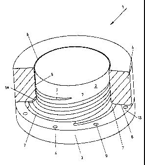
Referring first to Figures 1 and 2, the extruder die head 1,
according to the first narrower embodiment of this invention,
includes an inner cylindrical mandrel 2, which has an integral
outwardly projecting flange-shaped foot 3. The mandrel 2 is
enclosed by the outer concentric jacket 4. Between the outside
wall of the mandrel 2 and the inside wall of the jacket 4
there is an annular channel 5, which terminates as the die
slit 6. Starting from adjacent the flange-shaped foot 3, the
outside wall of the mandrel 3 includes several rows of grooves
7. The initial part of each groove has a closed end, and is
formed as a decreasing radius spiral. Each groove extends
through the transition region 5A and continues as a helical
groove on the outside of the mandrel 2. The depth of each
groove 7 decreases towards the die slit 6, so that the polymer
melt, flowing in the grooves 7, overflows the webs between the
grooves and is rerouted more and more into the axial
direction. In the transition region 5A the angle 3A between
the flange-shaped foot 3 and the cylindrical mandrel 2, and
the inside corner 4A of the cylindrical jacket 4 are rounded
off, so that the annular channel includes the transition
region.
The outer concentric jacket 4 has a first radial bottom face
8, which rests on the outwardly projecting radial annular
7
CA 02330928 2006-10-31
surface 13 of the flange-shaped foot 3. As shown, the
cooperating joint faces 13 and 8 are both flat; other profiles
can be used if desired. The flange-shaped foot 3 is provided
with boreholes 9, through which expansion screws 10 are
inserted, which are screwed into the corresponding threaded
boreholes of the concentric jacket 4. The expansion screws 10
are chosen so that even when the extruder die head is hot, the
cooperating joint surfaces 13 and 8 are forced together, so
that the surfaces 13 and 8 are connected together without a
gap and mate sealingly with each other, over both the flat
areas and the web surfaces between the grooves 7.
The polymer melt is fed by an extruder(not shown) through the
channel 11 and bore 12 to the spiral part of each groove 7,
adjacent to its closed end. Each of the grooves 7 has a
connection to a bore 12. The polymer melt issues from the
grooves 7 in the transition region 5A between the flange-
shaped foot 3 and the mandrel 2, enters into the annular
channel 5 and then flows with increasing axial flow to, and
finally exits through, the annular die slit 6.
The flange-shaped foot 3 is conveniently shaped as a disc,
which includes the channel 11 and the bores 12.
Figures 3 and 4 show a second narrower embodiment of a die
head 20. In this construction, a cylindrical mandrel 21 is
inserted into a blind borehole in the outer concentric jacket
22, the mandrel 21 having a radially extending circular flat
second bottom face 24, thus forming the annular channel 23
8
CA 02330928 2006-10-31
between the inside wall of the borehole and the outer surface
of the mandrel 21.
As can be seen in Figures 3 and 4, the mandrel 21 includes a
number of grooves 25 which extend through the transition
region. A part of each groove 25 is formed as an increasing
radius spiral, in the flat bottom face 24 of the mandrel 21,
and in part as a helical groove in the outer surface of the
mandrel 21. The depth of the grooves 25 decreases toward the
die slit 26, so that the melt overflows the webs of the
grooves and assumes an axial flow in the annular channel 23.
Referring also to Figure 5, the radial floor of the blind
borehole is flat and parallel to the face 24 so that the
mandrel bottom face 24 and the floor mate sealingly. The
mandrel 21 is fastened to the floor with expansion screws 28,
located in boreholes 29 and screwed into threaded boreholes
30. Hence the bottom face 24 of the mandrel 21 lies with its
surface in sealing engagement with the flat floor of the blind
borehole. The melt-feeding channels 31, 32 are connected to
the grooves 25 near to their closed ends, at the outer end of
the spiral part of each groove 25.
Figure 6 shows an axial cross section of a third narrow
embodiment of the extruder die head, which has several
differences from the constructions shown in Figures 1 - 5.
Referring to Figure 6 broadly, inspection of Figures 2 and 5
shows that those die heads are each essentially a two part
construction, with the radial joint either outside the
9
CA 02330928 2006-10-31
mandrel(Figure 2) or beneath the mandrel(Figure 5); in
contrast the die head in Figure 6 shows an alternative three
part construction, utilizing an outer concentric jacket 53
with a first radial bottom face, an inner cylindrical mandrel
50 with a second radial bottom face, both of which are mounted
onto cooperating radial flat surfaces provided on the die
block 41. Thus although this is a three part construction, all
of the joint faces are still radial, and therefore are not
affected by differential thermal expansion of the three parts.
In more detail, Figure 6 shows an axial cross section of a
third narrow embodiment of the extruder die head, which serves
to coextrude up to three different types of polymer melt. The
die head 40 comprises five parts. The die head is assembled
onto the die body 41, which forms the base of the die head,
and to which the other four parts are attached. The die body
41 includes a central circular region with a flat surface 42.
Adjoining this central circular region are three flat radial
annular surfaces 46, 47 and 48, with rounded off steps 43, 44,
45 in sequence between them. The die block 41 thus includes
four concentric radial surfaces: the central circular one 42,
and three annular ones 46, 47, 48. A rotationally symmetrical
mandrel 50 is sealingly attached to the central flat surface
42. A part of the inner face of the mandrel 50 is conical,
and tapers outwardly in segments towards the annular channel
55A. On the annular surfaces 46 and 47 are mounted two rings
51 and 52, which are sealingly attached at their flat radial
bottom faces to the surfaces 46 and 47 respectively. Each
ring has one tapered face, and one more or less axial face.
Outside the ring 52 the concentric outer jacket 53 is
CA 02330928 2006-10-31
sealingly attached to the outermost flat surface 48, which
also has an internal surface matching that of the mandrel. As
shown schematically in Figure 6, the die block 41, the mandrel
50, the two rings 51 and 52, and the concentric jacket 53 are
all held together by suitably located expansion bolts as at
57, 58, 59 and 60. Additionally, the tapered faces of the
central core 50, the two rings 51 and 52, and the outer
concentric jacket 53, and the axial faces of the two rings 51
and 52 are also constructed to provide three annular channels
50A, 51A and 52A through which the three polymer melts flow.
To facilitate polymer melt flow, several sets of grooves are
cut into the central core 50, the ring 51, and the ring 52.
In each case, these grooves commence as increasing radius
spirals facing the flat surfaces 42, 46, and 47, and extend
beyond the transition regions onto the outer conical, or
cylindrical, surfaces of the central core 50, the ring 51, and
the ring 52 as helical grooves. These grooves decrease in
depth towards the die slit 55. Each groove is connected to a
polymer melt feed line, as shown at 62, 63 and 64. This
construction thus provides the three substantially concentric
annular channels 50A, 51A and 52A respectively between the
central core 50 and the ring 51, between the rings 51 and 52
and between the ring 52 and the outer jacket 53. These
annular channels empty into one another at the common
intersection 56 and then a single annular channel 55A
continues to the die slit 55.
Since the mandrel 50, the rings 51 and 52, and the outer
jacket 53 have radial flat faces which are attached to
complementary flat radial surfaces in the die body 41, no
11
CA 02330928 2006-10-31
gaps or slits are present into which the polymer melt can
penetrate and accumulate. Further, since all of the faces,
although not co-planar, are all radially aligned, no slits or
gaps can arise due to differential thermal expansion of the
parts making up the die head. The only paths through which
the polymer melts can flow are defined by the cooperating
grooves and annular channels.
12