Language selection

Search

Patent 2331830 Summary

Third-party information liability

Some of the information on this Web page has been provided by external sources. The Government of Canada is not responsible for the accuracy, reliability or currency of the information supplied by external sources. Users wishing to rely upon this information should consult directly with the source of the information. Content provided by external sources is not subject to official languages, privacy and accessibility requirements.

Claims and Abstract availability

Any discrepancies in the text and image of the Claims and Abstract are due to differing posting times. Text of the Claims and Abstract are posted:

  • At the time the application is open to public inspection;
  • At the time of issue of the patent (grant).
(12) Patent Application: (11) CA 2331830
(54) English Title: IMPROVEMENTS IN OR RELATING TO THE SUPPORT OF PIPES AND OTHER ELEMENTS FROM WALLS AND CEILINGS
(54) French Title: PERFECTIONNEMENTS RELATIFS A LA FIXATION DE TUYAUX ET AUTRES ELEMENTS SUR DES PAROIS ET PLAFONDS
Status: Deemed Abandoned and Beyond the Period of Reinstatement - Pending Response to Notice of Disregarded Communication
Bibliographic Data
(51) International Patent Classification (IPC):
  • F16L 3/133 (2006.01)
(72) Inventors :
  • LEACH, BERNARD (United Kingdom)
(73) Owners :
  • BERNARD LEACH
(71) Applicants :
  • BERNARD LEACH (United Kingdom)
(74) Agent: MOFFAT & CO.
(74) Associate agent:
(45) Issued:
(86) PCT Filing Date: 1999-05-07
(87) Open to Public Inspection: 1999-11-11
Availability of licence: N/A
Dedicated to the Public: N/A
(25) Language of filing: English

Patent Cooperation Treaty (PCT): Yes
(86) PCT Filing Number: PCT/GB1999/001427
(87) International Publication Number: WO 1999057472
(85) National Entry: 2000-11-07

(30) Application Priority Data:
Application No. Country/Territory Date
9809765.2 (United Kingdom) 1998-05-07

Abstracts

English Abstract


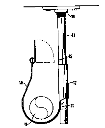
The present invention relates to improvements in or relating to the support of
pipes (11) and other elongate elements from walls and ceilings. In particular
it relates to a hanger of particular use in suspending pipes (11) and/or
cables, especially in heating and air-conditioning installations and plumbing
generally. There is described a support device comprising means to receive and
retain, in use, an object and including adjustable engagement means to receive
and retain a threaded rod (13). The engagement means comprises at least one
channel provided in a face of the support device, the channel being of similar
cross-sectional dimensions to the threaded rod and including a lateral toothed
ridge (25), the teeth of which, in use, engage the thread of the rod (13) to
retain the rod (13) in position within the channel.


French Abstract

La présente invention se rapporte à des perfectionnements relatifs à la fixation de tuyaux (11) et autres éléments oblongs sur des parois et plafonds. Elle se rapporte notamment à un élément de support conçu particulièrement pour fixer des tuyaux (11) et/ou des câbles, notamment dans des installations de chauffage ou de climatisation et de manière générale en plomberie. L'invention se rapporte à un dispositif de support comportant un organe conçu pour recevoir et retenir, en cours d'utilisation, un objet et comprenant un organe d'accouplement réglable conçu pour recevoir et retenir une tige filetée (13). L'organe d'accouplement comporte au moins une gorge ménagée sur une face du dispositif de support, ladite gorge ayant des dimensions de section transversale identique à celle de la tige filetée et comportant une arête (25) munie de dents qui, en cours d'utilisation, entre en contact avec le filetage de la tige (13) de manière à maintenir celle dernière dans sa position à l'intérieur de la gorge.

Claims

Note: Claims are shown in the official language in which they were submitted.

5
CLAIMS.
1. A support device (10) comprising pans to receive and retain, in use, an
object
and including adjustable engagement means to receive and retain a threaded rod
(13)
wherein the engagement means comprises a channel (12) provided in a face (15)
of the
support device, the channel being of similar cross-sectional dimensions to the
threaded
rod (13) and including a lateral toothed ridge (25), the teeth of which, in
use, engage
the thread of the rod to retain the rod in position within the channel.
2. A support device as claimed in Claim 1 comprising two channels (12) in the
face (15) of the device, each channel being adapted to receive a threaded rod
(13a,
13b) of different cross-section.
3. A support system comprising a threaded socket (16) including means for
securing the socket (16) to a surface; a complementarily threaded and (13);
and a
support device (10) as claimed in Claim 1 or Claim 2.
4. A method of coupling an object to a threaded rod, the method comprising the
steps of providing the object with a channel of similar cross-sectional
dimensions as the
threaded rod, which channel comprises a lateral toothed ridge, the teeth of
which are
selected to be of similar size and pitch to the thread of the rod.

Description

Note: Descriptions are shown in the official language in which they were submitted.


.. .. .... .. ..
.. .. .. . . . .. . ..
. . . . . . .... . ..
..
. . . ..
~ ... .... .. ... .. ..
IMPROVEMENTS IN OR RELATIrTG TO THE SUPPORT OF PIPES AND
OTHER ELEMENTS FROM WALLS AND CEILINGS.
The present invention relates to improvements in or relating to the support of
pipes
and other, typically, elongate elements from walls and ceilings. In particular
it relates to
a hanger of particular use in suspending pipes and/or cables, especially in
hewing and
air-conditioning installations and ph~mbing generally.
Conventionally, in heating or air-conditioning installaxions, pipes are
typically
suspended from a ceiling or floor joists by means of a threaded drop rod which
engages at its upper end a corresponding threaded coupling secured to the
ceiling or
joist and at its lower end, a munsing ring - a two-part ring which can be
closed once
the pipe has been inserted. This method requires very accurate cutting to
length of the
threaded rod to ensure that the pipes run horizontally or with the desired
incline.
US 4641989 descn'bes an extension clip for attaching threaded end portions to
a plain
rod. The clip is cut from flat metal plate and is shaped into a hollow form
having
clinch-type ears at one end for gripping the plain rod and inwardly bent tabs
at its
opposite end to form means for threadedly engaging threaded rod end portions.
Intermediate the clinch ears and the thread forming tabs additional tabs are
provided
which act as stops for determining the position of the plain rod and the
threaded rod
ends in the clip.
There is a need to provide an improved system of hanging pipework or other
elements
which avoids the need for accurate cutting of the threaded drop rods to length
.
In its broadest sense, in one aspect, the present invention provides a support
device
comprising means to receive and retain, in use, an object and including
adjustable
engagement means to receive and retain a threaded rod. The engagement means
comprises at least one channel provided in a face of the support device, the
channel
::::::.:::.::::.:::>:::.:::.::.::.:::.::.::.:::::::.:::.::.:::.::::>;. .~':;',
-.,.:~~a ::"~>~ .;.,;
::::::::::.::.::::::::::::::::::::.~::::::.:~.:::::::.~:. ~, .... .,::
........ ~ : 1 20 _ _ ;...
..:.~.'.~'. : .~ $30 ~:.' ~: :. >~
':.::.;:_:::::::.::.:CA ~:~x.~ 33 .~"~.'r~:.: ~ DO 11 07

....:.. ....
:.::r.w::;:a:.:.,i.,<.,:.::::::.;,:x.;!!:s:.;i;.::i,.,.i,.ro::.:::a:..:i.
::.:::::..:.......................
.:::::::.... .:.~::::::::.~::._::::::: x.:::o-
:ii::c:an,..ii::i>:::ox.
.-::> ::: :::'..::::::::: .::::::::::::::::::::::::
~:..:
:::::.~: :.::.
::: : ..15 a . :11 n .::: .:: h i.: .:.
: :. . :: ~... ':
:
:::::::::::::::'.
~:.:i
~
~
~L~
~~
:>::::~::C:'
.... .. .: ::: ...u.::.:::.v: ::v:::::::::::::::;:..::vvv:..:
:
w:::::::.v:.v:::.:............'i..v:::::.v::TV: v: :v.
..
..: v: ...... ..v.:..:. ...::..... .
v;: i:.%.::: i%::: ~ v...:........:..v.. ::.v..: ..
i: ii'f.4:3:.:.u.;.:y:ns. uu.,.u.\::.... :. .
v:: > :
.;:: v:::
.: n.;::::
~n .:.....
. .:.
.. vv :::rvi.s.,.
.s3 :v:::ri::f>v~..:
1 . . . . . . . . .
. . .
1 1 .. . . . . . . . .
.
1 . . . . . . .
.
. . . . . . . . .
. . .
. . . . . . . . . .
.
1$ ... .... .. ... .. ..
being of similar cross-sectional dimensions to the threaded rod and including
a lateral
toothed ridge, the teeth of which, in use, engage the thread of the rod to
retain the rod
in position within the channel
In a further aspect, the present invention provides a support system
comprising a
threaded socket including means for securing the socket to a surface; a
complementanly threaded rod; and a support element comprising means to receive
and
retain, in use, an object and including adjustable engagement means to receive
and
,~~:~w.: v:: ::
>:~~~CA~023318 020 0'-11-0~ AMENDED SrIEET

WO 99/57472 PCT/GB99/01427
2
retain the threaded rod; wherein the engagement means comprises a channel
provided
in a face of the support device, the channel being of similar cross-sectional
dimensions
to the threaded rod and including a lateral toothed ridge, the teeth of which,
in use,
engage the thread of the rod to retain the rod in position within the channel.
In a yet further aspect, the present invention provides a method of coupling
an object
to a threaded rod, the method comprising the steps of providing the object
with a
channel of similar cross-sectional dimensions as the threaded rod, which
channel
comprises a lateral toothed ridge, the teeth of which are selected to be of
similar size
and pitch to the thread of the rod.
The above and other aspects of the present invention will now be described in
further
detail, by way of example only, with reference to the accompanying drawings,
in
which:
Figure 1 is a side view of an embodiment of a support device in accordance
with the
present invention;
1 S Figure 2 is a rear view of the embodiment of Figure 1;
Figure 3 is a front view of the embodiment of Figure l;
Figure 4 is a plan view of the embodiment of Figure 1; and
Figure 5 is a section on the line V-V in Figure 2.
Referring to the figures, there is shown support device in the form of a pipe
hanger 10
supporting a pipe 11 shown in cross-section. The pipe hanger 10, which can be
bent
from sheet metal, has a generally U-shaped form when viewed side-on. The
hanger 10
includes two generally L-shaped elongate lugs 12 extending from and along the
rear
face thereof. In use, these lugs form a channel with the back-plate 15 of the
hanger to
receive and engage a threaded drop rod 13 which is secured to the ceiling or a
joist in a
conventional manner, as shown, by means of a threaded socket 16 screwed to the
ceiling. As shown, in the preferred embodiment, each channel is adapted to
engage a
CA 02331830 2000-11-07

WO 99/57472 PCTlGB99/01427
3
rod of different diameter, such as 8mm (13a) or lOmm (13b). Obviously, only
one
channel need be used at any one time. As shown in Figure 4, the edges of the
lugs 12
curve inwardly to securely engage the rod 12. In this preferred embodiment, an
aperture 20 is punched in the metal sheet of the hanger such that the metal
thereby
caused to protrude from the rear face of the hanger forms a lip 21 against
which, in
use, the threaded rod 13 is pressed, to retain the rod laterally in position.
The hanger is provided with a lateral toothed ridge 25 associated with each
channel
and forming an additional short side wall to retain threaded rod 13. Typically
each
toothed ridge is formed by punching or otherwise forming the appropriate shape
in the
back-plate of the hanger and then bending backwardly to the form shown in the
figures. The dimensions of the teeth of the ridge are selected to correspond
to the
pitch of the groove of the threaded rod. By this means, a rod is securely held
in place
within the hanger or conversely, the hanger is securely held upon the threaded
rod.
The hanger IO can be positioned at any height simply by clipping it onto the
threaded
rod 13 at the desired point. It no longer becomes necessary to cut the rod 13
to
precisely the correct length.
In the embodiment shown, there is also provided a clip at the top of the
hanger 10 to
prevent the pipe 11 from being lifted vertically out of the hanger. The clip
comprises a
tongue 30 pivotally mounted upon the front upright of the hanger. The tongue
30
includes a lug 31 which, in use, locates in a corresponding keyhole aperture
32 within
the back plate 15. As shown, in a preferred embodiment, the aperture 32 is
provided
within a portion of the back plate 15 which extends, in the form or a further
tongue,
above the main body of the hanger and is divided therefrom by perforations 33
forming
a line of weakness. Once the tongue 30 of the clip has been located within the
aperture
and is pushed down to its lowest extent, the further tongue can be bent over
along the
line of weakness to retain the tongue 30 in position. In this position, lug 32
also acts
to prevent sideways movement of the threaded rod.
CA 02331830 2000-11-07

WO 99/57472 PCT/GB99/01427
4
As has been mentioned above, in air-conditioning and similar installations,
condensation pipes must be accurately inclined to take the water to the lowest
point in
the installation. With the prior art supporting systems, this involves
accurate cutting of
the drop rods prior to installation. With the hangers of this invention, the
hangers can
be set approximately, the pipework can then be installed and the lengths of
the drop
rods 13 adjusted, if necessary, to ensure the correct inclination. The hangers
typically
provide su~cient room for two pipes and also for electrical cables as
required.
Although described herein with respect to the suspension of pipes and cables,
particularly in the context of heating and air-conditioning installation, the
present
invention is equally applicable to suspension of other articles. For example,
hangers 10
can be used individually in much the same way as a conventional hook. The
system
will, accordingly, be suitable for a range of uses in the home, in shop-
fitting and other
industrial uses.
CA 02331830 2000-11-07

Representative Drawing
A single figure which represents the drawing illustrating the invention.
Administrative Status

2024-08-01:As part of the Next Generation Patents (NGP) transition, the Canadian Patents Database (CPD) now contains a more detailed Event History, which replicates the Event Log of our new back-office solution.

Please note that "Inactive:" events refers to events no longer in use in our new back-office solution.

For a clearer understanding of the status of the application/patent presented on this page, the site Disclaimer , as well as the definitions for Patent , Event History , Maintenance Fee  and Payment History  should be consulted.

Event History

Description Date
Application Not Reinstated by Deadline 2003-05-07
Time Limit for Reversal Expired 2003-05-07
Deemed Abandoned - Failure to Respond to Maintenance Fee Notice 2002-05-07
Inactive: Cover page published 2001-03-09
Inactive: First IPC assigned 2001-03-07
Inactive: Notice - National entry - No RFE 2001-02-27
Inactive: Inventor deleted 2001-02-26
Application Received - PCT 2001-02-19
Application Published (Open to Public Inspection) 1999-11-11

Abandonment History

Abandonment Date Reason Reinstatement Date
2002-05-07

Maintenance Fee

The last payment was received on 2001-04-09

Note : If the full payment has not been received on or before the date indicated, a further fee may be required which may be one of the following

  • the reinstatement fee;
  • the late payment fee; or
  • additional fee to reverse deemed expiry.

Please refer to the CIPO Patent Fees web page to see all current fee amounts.

Fee History

Fee Type Anniversary Year Due Date Paid Date
Basic national fee - small 2000-11-07
MF (application, 2nd anniv.) - small 02 2001-05-07 2001-04-09
Owners on Record

Note: Records showing the ownership history in alphabetical order.

Current Owners on Record
BERNARD LEACH
Past Owners on Record
None
Past Owners that do not appear in the "Owners on Record" listing will appear in other documentation within the application.
Documents

To view selected files, please enter reCAPTCHA code :


To view images, click a link in the Document Description column. To download the documents, select one or more checkboxes in the first column and then click the "Download Selected in PDF format (Zip Archive)" or the "Download Selected as Single PDF" button.

List of published and non-published patent-specific documents on the CPD .

If you have any difficulty accessing content, you can call the Client Service Centre at 1-866-997-1936 or send them an e-mail at CIPO Client Service Centre.


Document
Description 
Date
(yyyy-mm-dd) 
Number of pages   Size of Image (KB) 
Representative drawing 2001-03-09 1 5
Cover Page 2001-03-09 2 61
Abstract 2000-11-07 1 55
Description 2000-11-07 5 214
Claims 2000-11-07 1 43
Drawings 2000-11-07 3 43
Reminder of maintenance fee due 2001-02-26 1 112
Notice of National Entry 2001-02-27 1 194
Courtesy - Abandonment Letter (Maintenance Fee) 2002-06-04 1 183
PCT 2000-11-07 11 387
Fees 2001-04-09 1 38