Language selection

Search

Patent 2332285 Summary

Third-party information liability

Some of the information on this Web page has been provided by external sources. The Government of Canada is not responsible for the accuracy, reliability or currency of the information supplied by external sources. Users wishing to rely upon this information should consult directly with the source of the information. Content provided by external sources is not subject to official languages, privacy and accessibility requirements.

Claims and Abstract availability

Any discrepancies in the text and image of the Claims and Abstract are due to differing posting times. Text of the Claims and Abstract are posted:

  • At the time the application is open to public inspection;
  • At the time of issue of the patent (grant).
(12) Patent: (11) CA 2332285
(54) English Title: CUTTING INSERT FOR GROOVING
(54) French Title: PLAQUETTE DE RAINURAGE
Status: Deemed expired
Bibliographic Data
(51) International Patent Classification (IPC):
  • B23B 27/04 (2006.01)
(72) Inventors :
  • TAGTSTROM, PAR (Sweden)
  • WIMAN, JORGEN (Sweden)
(73) Owners :
  • SANDVIK INTELLECTUAL PROPERTY AB (Sweden)
(71) Applicants :
  • SANDVIK AKTIEBOLAG (Sweden)
(74) Agent: GOWLING WLG (CANADA) LLP
(74) Associate agent:
(45) Issued: 2007-04-03
(86) PCT Filing Date: 1999-05-20
(87) Open to Public Inspection: 1999-12-02
Examination requested: 2003-11-20
Availability of licence: N/A
(25) Language of filing: English

Patent Cooperation Treaty (PCT): Yes
(86) PCT Filing Number: PCT/SE1999/000860
(87) International Publication Number: WO1999/061187
(85) National Entry: 2000-11-14

(30) Application Priority Data:
Application No. Country/Territory Date
9801800-5 Sweden 1998-05-22

Abstracts

English Abstract


A cutting insert for grooving
operations includes a shank portion and a forward
cutting head. The shank portion includes
an upper surface, a bottom surface and side
surfaces, wherein a line of intersection
between the upper side and a forward clearance
face forms a main cutting edge. Between
the main cutting edge and a secondary
cutting edge there is provided a corner cutting
edge. The comer cutting edge comprises a
primary curved edge with a first radius
extending from the main cutting edge, and a
secondary curved edge with a second radius,
larger than the first radius, that extends from
the primary edge to a side edge and oriented
perpendicular to the main cutting edge. The
cutting insert also comprises an upper side
confined by two longitudinal ridges and an
elongated chip forming recess therebetween.


French Abstract

L'invention concerne une plaquette destinée à des opérations de rainurage et comprenant une partie tige et une tête de coupe avant. La partie tige comprend une surface supérieure, une surface inférieure et des surfaces latérales, une ligne d'intersection entre le côté supérieur et une face en dépouille avant constituant un bord de coupe principal. Un bord de coupe angulaire est situé entre le bord de coupe principal et un bord de coupe secondaire. Le bord de coupe angulaire comprend un premier bord incurvé doté d'un premier rayon s'étendant du principal bord de coupe, et un deuxième bord de coupe doté d'un deuxième rayon qui est plus large que le premier rayon, qui s'étend à partir du bord latéral et qui est orienté perpendiculairement par rapport au principal bord de coupe. La plaquette comprend également un bord supérieur flanqué de deux arêtes longitudinales entre lesquelles se trouve un creux allongé destiné à la formation d'un copeau.

Claims

Note: Claims are shown in the official language in which they were submitted.


7


CLAIMS

1. A metal cutting insert comprising:
a shank portion and a cutting head, the shank portion being elongated in a
direction defining a longitudinal axis of the shank, the cutting head located
at a
longitudinal end of the shank portion, the cutting head including an upper
surface, a
bottom surface, two side clearance surfaces each extending between the upper
and
bottom surfaces, and a front clearance surface disposed between the side
clearance
surfaces and extending between the upper and bottom surfaces, an intersection
between the upper surface and the front clearance surface forming a main
cutting
edge extending generally perpendicular to the longitudinal axis, the main
cutting
edge being straight as viewed in a direction perpendicular to the upper
surface, the
intersection between the upper surface and each side clearance surface
defining a
side edge having a clearance angle;
the upper surface including a pair of ridges extending generally
longitudinally
on opposite sides of the longitudinal axis and spaced apart to define a chip-
forming
recess between one another;
the cutting insert further including corner cutting edges disposed at
respective
ends of the main cutting edge, the corner cutting edges extending between
respective ones of the side edges and the main cutting edge, each corner
cutting
edge including a primary curved edge of constant radius extending from the
main
cutting edge, and a curved wiper edge of constant radius extending from the
primary
curved edge to the side edge, the primary curved edge having a smaller radius
of
curvature than the curved wiper edge.
2. The cutting insert according to claim 1 wherein the side edge has a radius
of curvature smaller than the radius of curvature of the wiper edge.
3. The cutting insert according to claim 2 wherein the side edge forms a
clearance angle in the range of 1 to 5°.
4. The cutting insert according to claim 3 wherein the radius of curvature of
the primary curved edge is in the range of 0.1 to 12.0 mm.
5. The cutting insert according to claim 4 wherein the radius of curvature of
the wiper edge is in the range of 2.5 to 20.0 mm.


8


6. The cutting insert according to claim 5 wherein a radius of curvature of
the
side edge is in the range of 0.1 to 2.0 mm.
7. The cutting insert according to claim 1 wherein the radius of curvature of
the primary curved edge is in the range of 0.1 to 12.0 mm.
8. The cutting insert according to claim 7 wherein the radius of curvature of
the primary curved edge is in the range of 0.2 to 2.0 mm.
9. The cutting insert according to claim 1 wherein the radius of curvature of
the wiper edge is in the range of 2.5 to 20.0 mm.
10. The cutting insert according to claim 9 wherein the radius of curvature of
the wiper edge is in the range of 2.5 to 5.0 mm.
11. The cutting insert according to claim 2 wherein the radius of curvature of
the side cutting edge is in the range of 0.1 to 2.0 mm.
12. The cutting insert according to claim 11 wherein the radius of curvature
of
the side edge is in the range of 0.2 to 0.5 mm.

Description

Note: Descriptions are shown in the official language in which they were submitted.


CA 02332285 2000-11-14
WO 99/61187 PCT/SE99/00860
CUTTING INSERT FOR GROOVING
Background of the Invention
The present invention relates to a cutting insert for grooving operations.
In particular, the present cutting insert according to the invention is
suitable for
S radial grooving, although it also can be used for various axial grooving and
parting off operations, as well as for axial and radial longitudinal turning
operations.
During such machining, chip~breaking and chip formation are often of
decisive importance for undisturbed production. Modem high productive
machines put very high claims on good chip transport. Long uncontrollable
chips can easily cause machine interruptions and cessation. Chip control must
therefore be given high priority and governs to a high degree the tool design.
Cutting inserts intended for grooving operations and parting off are
usually clamped in a holder, which is blade shaped in order to be useful in
the
slot produced. The expression "holder of blade type" is also intended to
comprise slot mills. Such cutting inserts are for example known from US-A-
4,778,311, USA-4,992,008, US-A-5,135,336 and US-A 5,423,639. At the
same time there is nowadays a demand if possible to be able to obtain
improved surface finish of the surfaces in the slots produced. A first purpose
is
to produce a cutting insert, which is well suited to give improved finish of
the
surfaces in the slot produced in a work piece.
It is another purpose of the present invention to produce a cutting insert,
which is well suited for repeated radial grooving.
It is a third purpose to produce a cutting insert, which gives the
possibility to achieve good surface roughness in combination with high feed
and good chip control.

CA 02332285 2000-11-14
WO 99/61187 PCT/SE99/00860
-2-
It is a fourth purpose with the present invention to produce a cutting
insert which also can be used for longitudinal turning in particular on the
bottom surface of a widened slot.
~, m~~ of the Invention
These and other purposes have been achieved by a metalcutting insert
comprising a shank portion and a cutting head. The shank portion defines a
longitudinal axis, and the cutting head is located at a longitudinal end of
the
shank portion. The cutting head includes an upper surface, a bottom surface,
two side clearance surfaces each extending between the upper and bottom
surfaces, and a front clearance surface disposed between the side clearance
surfaces and extending between the upper and bottom surfaces. An
intersection between the upper surface and the front clearance surface farms a
main cutting edge extending generally perpendicular to the longitudinal axis.
The intersection between the upper surface and each side clearance surface
defines a side' edge having a clearance angle. The upper surface includes a
pair
of ridges extending generally longitudinally on opposite sides of the
longitudinal axis and spaced apart to define a chip-forming recess between one
another. The cutting insert further includes comer cutting edges extending
between respective ones of the side edges and the main cutting edge. Each
corner cutting edge includes a primary curved edge extending from the main
cutting edge, and a curved wiper edge extending from the primary curved edge
to the side edge. The primary curved edge has a smaller radius of curvature
than the curved wiper edge.

CA 02332285 2006-05-09
-3-
Brief Description of the Drawing
For illustrating but non limiting purposes preferred embodiments of the
invention will now be described in more detail under reference to the enclosed
drawings. These are presented shortly hereby:
Figure 1 shows a cutting insert according to the invention in a perspective
view
as seen obliquely from above.
Figure 2a shows the same cutting insert as in figure 1 as seen straightly from
its forward end.
Figure 2b shows an alternative embodiment of a cutting insert.
Figure 3 shows the same cutting insert as in figure 1, straight from above.
Figure 4 shows the same cutting insert as in figure 1, as seen from above and
in engagement with a work piece.
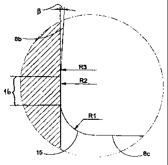
Figure 5 shows an enlarged detail of a cutting corner of the cutting insert
that is
shown in figure 4.
Detailed Description of Preferred
Embodiments of the Invention
Figures 1-3 show a cutting insert for grooving according to the invention
including a body of parallelepipedic shape with an upper surface 1, a bottom
surface 2,
a forward end surface 3, a rear end surface 4, as well as opposite plane
parallel side
faces 5, 6. The cutting insert is generally made of coated or sometimes non-
coated
cemented carbide; the upper surface 1 and the bottom surface 2 are each shaped
with
a longitudinally concave V-shaped keyway 1a and 2a. Alternatively the cutting
insert
can be as the embodiment according in figure 2b, where the bottom support
surfaces
2b, 2c on respective sides of the central concave 2a, have an inclination and
are
intended to support against corresponding inclined support surfaces in a blade
holder
in the way that is described in Swedish Patent No. 9703434-2.

CA 02332285 2006-05-09
-4-
The central part of the cutting insert is a shank portion defining a
longitudinal axis. A
cutting head is formed at each longitudinal end of the shank portion. Each
cutting head has
an end surface composed of a front clearance surface 7 that by the
intersection with the
upper surface 1 forms a transverse cutting edge 8a, which via a corner 15,16
extends to side
edges 8b. The clearance surface 7 intersects, via a transverse break line 9, a
lower front
surface 10, which extends essentially perpendicularly toward the bottom
surface 2. Each of
the cutting heads has two side clearance surfaces 11,12, situated laterally
outwardly with
respect to the longitudinal axis, and which via a break line 13 merge into
respective ones of
the side surfaces 5.
The upper surface disposed adjacent the cutting edge 8 is a shaped surface
that
extends inwards from the cutting edge 8 and is formed with a chip former 14 in
the shape of
a recess that intersects the cutting edge and passes between two separate
ridges 20 and
21. In this way the cutting edge 8 becomes concave in relation to the upper
surface 1 and is
formed with a chip angle which varies along the cutting edge of the insert
such that the chip
angle is more positive at the central portion 8a than at the end portions 8c
and 8d of the
main cutting edge. That is, the chip angle formed between the clearance
surface 7 and a
central recess 14a of the chip former, is smaller than chip angles formed
between the
clearance surface 7 and the ridges 20,21.
The inner side faces 14b and 14c, which define the sides of the chip former
14, form
an angle a therebetween and straddle the central, axially extending recess 14a
of the chip
former, which recess extends axially along the upper surface 1. The depth of
the recess 14a
first increases from the cutting edge and, at some distance from said cutting
edge 8, begins
to diminish. The angle a extends uniformly in the axial direction, in a
direction away from the
cutting edge 8. Simultaneously the design is such that the obliquely

CA 02332285 2000-11-14
WO 99/61187 PCT/SE99/00860
-5-
downwards inclined inner side faces 14b and 14c of the ridges 20 and 21 have
a width that diminishes uniformly from a broad area near the cutting edge to a
minimum area at the level of raised portions i4d, 14e which lie above the
cutting edge 8.
The width of the inner side faces 14b, 14c remains essentially constant
in a rearward direction after passing the portions 14d and 14e. The side faces
14b and 14c have portions which converge rearwardly into a concave shaped
end portion 14f.
In figure 4-5 there is shown a cutting insert according to figure 1-3 in
1'0 engagement with a work piece A.
Each comer portion on the upper side 1 of the insert includes a varying
convex radius of curvature. That is, each corner includes a primary curved
edge 15, which extends to the adjacent end portion 8c of the main cutting edge
8, as well as a secondary cutting edge 16 or "wiper edge." In order to
reinforce
the cutting edge, this wiper edge 16 could possibly be equipped with a primary
chamfer. As shown in figure 5 the wiper edge 16 is formed with a radius R2
that is substantially bigger than the radius R1 of primary edge 15, whereby
the
edge 16 appears almost straight in Fig. 5. Wiper edge 16 extends rearvvardly
to
the side edge 8b, the radius R3 of which is substantially less than R2. The
curved edge 8b extends rearwardly with a side clearance angle of about 1-

preferably 2-3°.
Radius R2 of the wiper edge 16 is chosen such that the edge y 6 acts like
a round insert. The wiper edge can consequently be considered as being
analogous to a segment of an imaginary circular round insert. The substantial
advantage of the present insert compared with a round insert is that the
primary
edge 15 and the wiper edge 16 generate considerably narrower and thicker
chips than compared with a round insert under the same operation parameters,
which gives good chip control. Since radius R2 is chosen considerably larger

CA 02332285 2000-11-14
WO 99/61187 PCT/SE99/00860
-6-
than R1, a favorable "wipe" effect is obtained which gives considerably
improved surface finish. As a further consequence, a subsequent finishing
operation can be eliminated.
In order to attain optimal chip control, the different radii of the various
curved edges should be chosen within the following intervals:
R1: 0.1-12mm, preferably 0.2-2.0
R2: 2.5»20 mm, preferably 2.5-5.0
R3: 0.1-2 mm, preferably 0.2-0.5
Although the present invention has been described in connection with a
preferred embodiment thereof, it will be appreciated by those skilled in the
art
that additions, deletions, modifications, and substitutions not specifically
described may be made without departing from the spirit and scope of the
invention as defined in the appended claims.

Representative Drawing
A single figure which represents the drawing illustrating the invention.
Administrative Status

For a clearer understanding of the status of the application/patent presented on this page, the site Disclaimer , as well as the definitions for Patent , Administrative Status , Maintenance Fee  and Payment History  should be consulted.

Administrative Status

Title Date
Forecasted Issue Date 2007-04-03
(86) PCT Filing Date 1999-05-20
(87) PCT Publication Date 1999-12-02
(85) National Entry 2000-11-14
Examination Requested 2003-11-20
(45) Issued 2007-04-03
Deemed Expired 2017-05-23

Abandonment History

There is no abandonment history.

Payment History

Fee Type Anniversary Year Due Date Amount Paid Paid Date
Registration of a document - section 124 $100.00 2000-11-14
Application Fee $300.00 2000-11-14
Maintenance Fee - Application - New Act 2 2001-05-22 $100.00 2001-05-22
Maintenance Fee - Application - New Act 3 2002-05-20 $100.00 2002-04-19
Maintenance Fee - Application - New Act 4 2003-05-20 $100.00 2003-04-22
Request for Examination $400.00 2003-11-20
Maintenance Fee - Application - New Act 5 2004-05-20 $200.00 2004-04-22
Maintenance Fee - Application - New Act 6 2005-05-20 $200.00 2005-04-19
Registration of a document - section 124 $100.00 2005-05-27
Registration of a document - section 124 $100.00 2005-08-11
Maintenance Fee - Application - New Act 7 2006-05-22 $200.00 2006-04-13
Final Fee $300.00 2007-01-15
Maintenance Fee - Patent - New Act 8 2007-05-21 $200.00 2007-04-17
Maintenance Fee - Patent - New Act 9 2008-05-20 $200.00 2008-04-10
Maintenance Fee - Patent - New Act 10 2009-05-20 $250.00 2009-04-20
Maintenance Fee - Patent - New Act 11 2010-05-20 $250.00 2010-04-14
Maintenance Fee - Patent - New Act 12 2011-05-20 $250.00 2011-04-13
Maintenance Fee - Patent - New Act 13 2012-05-21 $250.00 2012-04-11
Maintenance Fee - Patent - New Act 14 2013-05-21 $250.00 2013-04-10
Maintenance Fee - Patent - New Act 15 2014-05-20 $450.00 2014-04-09
Maintenance Fee - Patent - New Act 16 2015-05-20 $450.00 2015-04-29
Owners on Record

Note: Records showing the ownership history in alphabetical order.

Current Owners on Record
SANDVIK INTELLECTUAL PROPERTY AB
Past Owners on Record
SANDVIK AKTIEBOLAG
SANDVIK INTELLECTUAL PROPERTY HB
TAGTSTROM, PAR
WIMAN, JORGEN
Past Owners that do not appear in the "Owners on Record" listing will appear in other documentation within the application.
Documents

To view selected files, please enter reCAPTCHA code :


To view images, click a link in the Document Description column. To download the documents, select one or more checkboxes in the first column and then click the "Download Selected in PDF format (Zip Archive)" or the "Download Selected as Single PDF" button.

List of published and non-published patent-specific documents on the CPD .

If you have any difficulty accessing content, you can call the Client Service Centre at 1-866-997-1936 or send them an e-mail at CIPO Client Service Centre.


Document
Description 
Date
(yyyy-mm-dd) 
Number of pages   Size of Image (KB) 
Cover Page 2001-03-12 1 51
Representative Drawing 2001-03-12 1 7
Abstract 2000-11-14 1 50
Description 2000-11-14 6 242
Claims 2000-11-14 3 70
Drawings 2000-11-14 2 64
Description 2006-05-09 6 230
Claims 2006-05-09 2 67
Representative Drawing 2007-03-14 1 10
Cover Page 2007-03-14 1 43
Assignment 2000-11-14 3 107
Assignment 2000-12-28 2 63
PCT 2000-11-14 4 168
Prosecution-Amendment 2000-11-14 1 20
Prosecution-Amendment 2003-11-20 1 33
Correspondence 2007-01-15 1 40
Prosecution-Amendment 2003-12-24 1 25
PCT 2000-11-15 4 174
Assignment 2005-05-27 7 209
Assignment 2005-08-11 6 275
Prosecution-Amendment 2005-11-10 3 109
Prosecution-Amendment 2006-05-09 6 197