Language selection

Search

Patent 2332418 Summary

Third-party information liability

Some of the information on this Web page has been provided by external sources. The Government of Canada is not responsible for the accuracy, reliability or currency of the information supplied by external sources. Users wishing to rely upon this information should consult directly with the source of the information. Content provided by external sources is not subject to official languages, privacy and accessibility requirements.

Claims and Abstract availability

Any discrepancies in the text and image of the Claims and Abstract are due to differing posting times. Text of the Claims and Abstract are posted:

  • At the time the application is open to public inspection;
  • At the time of issue of the patent (grant).
(12) Patent Application: (11) CA 2332418
(54) English Title: CABLE CONNECTION DEVICE AND METHOD
(54) French Title: PROCEDE ET DISPOSITIF DE RACCORDEMENT DE CABLE
Status: Deemed Abandoned and Beyond the Period of Reinstatement - Pending Response to Notice of Disregarded Communication
Bibliographic Data
(51) International Patent Classification (IPC):
  • H01R 04/2406 (2018.01)
  • H01R 13/50 (2006.01)
(72) Inventors :
  • MATHIESON, BRIAN DOUGLAS (Australia)
  • MATHIESON, EIAN DOUGLAS (Australia)
(73) Owners :
  • MATSON AUTOMOTIVE INDUSTRIES PTY. LTD.
(71) Applicants :
  • MATSON AUTOMOTIVE INDUSTRIES PTY. LTD. (Australia)
(74) Agent: OYEN WIGGS GREEN & MUTALA LLP
(74) Associate agent:
(45) Issued:
(86) PCT Filing Date: 1999-05-20
(87) Open to Public Inspection: 1999-11-25
Availability of licence: N/A
Dedicated to the Public: N/A
(25) Language of filing: English

Patent Cooperation Treaty (PCT): Yes
(86) PCT Filing Number: PCT/AU1999/000382
(87) International Publication Number: AU1999000382
(85) National Entry: 2000-11-15

(30) Application Priority Data:
Application No. Country/Territory Date
PP 3606 (Australia) 1998-05-20

Abstracts

English Abstract


A device for electrically connecting cables to each other or to an electrical
circuit. The device includes a housing (1), having at least one hinged wing
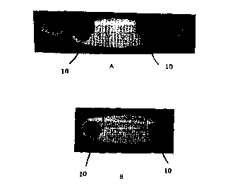
(11) or otherwise movable member. At least one conductive spike (10) is
provided within the housing such that, when the cable is positioned proximal
to the spike (10), and the hinged wing (11) is closed to cover the cable, the
spike (10) pierces through the insulation of the cable and the cable is
retained in electrical connection with the spike (10). The hinged wing (11) is
either permanently closed or may be reopened for release of the cable. Various
support means, such as by using biased projections (2, 3) may be used to urge
the cable into correct position. The electrical circuit may also be contained
within the housing.


French Abstract

L'invention porte sur un dispositif permettant de raccorder électriquement des câbles entre eux ou à un circuit électrique. Le dispositif comprend un corps (1) comportant au moins une ailette (11) articulée ou un autre élément amovible. Au moins une pointe (10) conductrice est ménagée dans le corps de sorte que, lorsque le câble est placé à côté de la pointe (10) et que l'ailette (11) articulée est fermée de façon à recouvrir le câble, la pointe (10) perce l'isolation du câble, ce dernier étant maintenu en connexion électrique avec la pointe (10). L'ailette (11) articulée soit est fermée en permanence, soit peut être réouverte pour dégager le câble. Différents organes de support, par exemple, des parties (2, 3) saillantes sollicitées, peuvent être utilisés pour pousser le câble en position correcte. Le circuit électrique peut également être contenu dans le corps.

Claims

Note: Claims are shown in the official language in which they were submitted.

-7-
THE CLAIMS
1. A device to facilitate electrical connections to a cable, wire or the like,
said device
including:
a housing having a hinged or otherwise movable covering; and,
at least one conductive spike provided substantially within said housing;
such that, in use, a portion of said cable or wire is positioned proximal to
said spike(s)
and said movable covering is closed to substantially surround said portion of
said cable or
wire, whereby said spike(s) is/are retained in electrical connection with said
cable or wire.
2. A device as claimed in claim 1, wherein said cable, wire or the like
includes an
insulative sheath therearound whereby, in use, said spike(s), pierce(s) said
insulative sheath
and contacts said wire or cable.
3. A device as claimed in claim 1 or 2, wherein said housing has retaining
means
associated therewith to permanently or removably retain said housing in a
closed position
about said cable or wire.
4. A device as claimed in claim 3, wherein said retaining means includes
locking pins and
locking pin receptors.
5. A device as claimed in any one of claims 1 to 4, wherein said housing
further includes
support means to urge said cable or wire in a direction towards said spike(s).
6. A device as claimed in claim 5, wherein said support means includes biased
projecting
members.
7. A device as claimed in claim 6, wherein said projecting members are
integrally formed
with said casing and are adapted to project in a substantially transverse
direction to the axial
direction of said cable.

-8-
8. A device as claimed in claims 6 or 7, wherein said projecting members have
shaped
ends adapted to at least partially surround said cable or wire.
9. A device as claimed in any one of claims 6 to 8, wherein two or more sets
of
projecting members are provided for retention of cables of varying diameter in
said housing,
each set of projecting members including at least one member of different
length.
10. A device as claimed in any one of claims 1 to 9, wherein said movable
member is
embodied in the form of a hinged wing.
11. A device as claimed in any one of claims 1 to 10, wherein two or more
housings are
provided, each for connection of a respective wire or cable.
12. A device as claimed in any of claims 1 to 11, wherein said device further
includes an
electrical circuit to be connected to said cable(s).
13. A device as claimed in any one of claims 1 to 12, wherein said housing(s)
are formed
of insulative, such as plastics, material.
14. A device to facilitate electrical connection to a plurality of cables,
wires or the like, said
device including:
a housing having a plurality of hinged or otherwise movable coverings;
each having at least one conductive spike provided substantially within said
housing;
such that, in use, a portion of one cable or wire is positioned proximal to a
spike and
each movable covering is closed to substantially surround it's respective
portion of cable or
wire, whereby each spike is retained in electrical connection with its'
respective cable or
wire.
15. A device as claimed in claim 14, further including an electrical circuit
for connection
to each of said plurality of cables.

-9-
16. A device to facilitate electrical connection to a pair of cables, wires or
the like, said
device including:
a housing having a pair of hinged wing members, each adapted to be closed
about a
respective cable or wire in a permanent or removable manner; and,
at least one conductive spike associated in each housing;
such that, in use, a portion of a cable or wire is positioned proximal to said
spike(s)
associated with a respective housing, and each hinged wing member is closed to
surround said
respective portion of cable, whereby said spike(s) is/are retained in
electrical connection with
said cable or wire.
17. A device as claimed in claim 16, wherein said housing further includes an
electrical
circuit for connection to each of said cables or wires.
18. A device, substantially as herein described with reference to the
accompanying
drawings.
19. A method of facilitating electrical connection to at least one cable,
wire, or the like
substantially as herein described.

Description

Note: Descriptions are shown in the official language in which they were submitted.


CA 02332418 2000-11-15
WO 99/60668 PCT/AU99/00382
-1-
Cable Connection Device And Method
Background Of The Invention
The present invention relates to a device with the capability of allowing
electronic circuits to
be easily fitted to pre-existing electrical cables. The device utilises a
method of facilitating
good electrical and mechanical contact with electrical cables, without any
need for alteration
of the electrical cables, and for retention of the cables in position. In
particular, the present
invention relates to such a device which is quickly and easily snap-fitted to
the cable(s).
Description Of The Prior Art
In the field of automotive power electronics, devices for monitoring and
control of electrical
characteristics, such as voltage levels, of the power circuitry are presently
provided pre-
attached to the electronic cabling to be used in the automotive application.
For example, charging leads for charging or obtaining charge from a power
source are
available with integrally formed electronic circuitry having the function of
preventing surges
in electronic variables, such as voltage fluctuations, which can occur when
current passes
from a voltage source. This can occur in situations such as using charging
cables to charge
the battery of a motor vehicle.
Certain electronic variable monitoring, such as current, voltage and power
signals and levels,
is presently available as a transportable diagnostic device for pre-existing
cabling. These
devices usually comprise a sharp metallic point which when pushed through
cable insulation
provides electrical contact with the conducting core of the electrical cable.
These devices
offer no permanent electronic monitoring, control or protection capabilities,
but rather serve
as a 'trouble-shooting' diagnostic.
This identifies a need for a device that may be used to easily attach an
arbitrary electronic
circuit to a wide range of pre-existing cables, either permanently or
temporarily.

CA 02332418 2000-11-15
WO 99/60668 PCT/AU99/00382
-2-
Summary Of The Invention
The present invention seeks to provide a casing for an electronic circuit such
that the casing
assists in making stable electrical contact between the electronic circuitry
integrally formed
within the casing and the electrical cables to be monitored or controlled.
The present invention seeks to provide a casing for housing an electronic
circuit, said casing
characterised in that it includes at least one cable connection means to
secure said casing to
a cable. Preferably said cable connection means is formed by a hinged wing
adapted to close
substantially about said cable. Also preferably said cable connection means
includes at least
one conductive spike adapted to pierce the insulative sheath of said cable. In
use, when said
cable is positioned within said cable connection means and said hinged wing is
closed
therearound, said insulative sheath of said cable is pierced by said
conductive spikes) to
facilitate an electrical connection between said cable and said electronic
circuit.
In one broad form the present invention provides a device to facilitate
electrical connections
to a cable, wire or the like, said device including:
a housing having a hinged or otherwise movable covering; and,
at least one conductive spike provided substantially within said housing;
such that, in use, a portion of said cable or wire is positioned proximal to
said spikes)
and said movable covering is closed to substantially surround said portion of
said cable or
wire, whereby said spikes) is/are retained in electrical connection with said
cable or wire.
Preferably, said cable, wire or the like includes an insulative sheath
therearound whereby,
in use, said spike(s), pierces) said insulative sheath and contacts said wire
or cable.
Also preferably, said housing has retaining means associated therewith to
permanently or
removably retain said housing in a closed position about said cable or wire.
In this preferred form, said retaining means includes locking pins and locking
pin receptors.

CA 02332418 2000-11-15
WO 99/60668 PCT/AU99/00382
-3-
Preferably, said housing further includes support means to urge said cable or
wire in a
direction towards said spike(s).
In this form, preferably, said support means includes biased projecting
members.
S
Perhaps most preferably, said projecting members are integrally formed with
said casing and
are adapted to project in a substantially transverse direction to the axial
direction of said
cable.
In a preferred form, said projecting members have shaped ends adapted to at
least partially
surround said cable or wire.
Also preferably, the device is embodied, wherein two or more sets of
projecting members are
provided for retention of cables of varying diameter in said housing, each set
of projecting
members including at least one member of different length.
In a most preferred form, said movable member is embodied in the form of a
hinged wing.
Most preferably, two or more housings are provided, each for connection of a
respective wire
or cable.
In a preferred embodiment, said device further includes an electrical circuit
to be connected
to said cable(s).
In a most preferred form, said housings) are formed of insulative, such as
plastics, material.
In a further broad form, the present invention provides a device to facilitate
electrical
connection to a plurality of cables, wires or the like, said device including:
a housing having a plurality of hinged or otherwise movable coverings;
each having at least one conductive spike provided substantially within said
housing;
such that, in use, a portion of one cable or wire is positioned proximal to a
spike and

CA 02332418 2000-11-15
WO 99/60668 PCT/AU99/0038Z
-4-
each movable covering is closed to substantially surround it's respective
portion of cable or
wire, whereby each spike is retained in electrical connection with its'
respective cable or
wire.
In this preferred form, the device preferably further includes an electrical
circuit for
connection to each of said plurality of cables.
In yet still a further broad form, the present invention provides a device to
facilitate electrical
connection to a pair of cables, wires or the like, said device including:
a housing having a pair of hinged wing members, each adapted to be closed
about a
respective cable or wire in a permanent or removable manner; and,
at least one conductive spike associated in each housing;
such that, in use, a portion of a cable or wire is positioned proximal to said
spikes)
associated with a respective housing, and each hinged wing member is closed to
surround said
respective portion of cable, whereby said spikes) is/are retained in
electrical connection with
said cable or wire.
In this form, preferably, said housing further includes an electrical circuit
for connection to
each of said cables or wires.
Brief Description Of The Drawings
The present invention will become more fully understood from the following
detailed
description of a preferred but non-limiting embodiment thereof, described in
connection with
the accompanying drawings, wherein:
Fig. 1 illustrates various views of a preferred embodiment of the present
invention,
and shows the lower half of the device;
Fig. 2 illustrates various views of a preferred embodiment of the present
invention,
and shows the upper half of the device;
Fig. 3 illustrates a preferred embodiment of the present invention, and shows
an
sectional view of the assembled device; and,
Fig. 4 illustrates end views of the assembled device.

CA 02332418 2000-11-15
WO 99/60668 PCT/AU99/00382
-5-
Detailed Description Of A Preferred Embodiment
Throughout the drawings, like numerals will be used to identify similar
features, except
where expressly otherwise indicated.
A preferred embodiment of the present invention is shown in Figs. 1, 2 and 3.
In this
embodiment the present invention provides a moulded plastic casing 1 which
houses a printed
circuit board 9 together with appropriate electronic components. For example,
the casing 1
may house the voltage monitoring and control electronic circuit disclosed in
the Applicant's
Australian Patent No. 620091.
Fig. 1 shows the lower half of the casing 1. Fig. 1(a) showing an elevational
view , Fig. 1(b)
showing a plan view, Fig. 1 (c) showing a bottom view, and, Fig. 1 (d) showing
an end
elevational view of a 'wing' of the device. The upper half 6 of the casing 1
is presented in
Fig. 2, with Fig. 2(a) showing a side elevational view, Fig. 2(b) showing a
top view, Fig.
2(c) showing a plan view and Fig. 2(d) showing a front elevational view.
Connecting these
halves together forms the device, shown in sectional view in Fig. 3, and as
illustrated in Fig.
4, Fig. 4(a) showing a side elevational view with the 'wings' open and Fig.
4(b) showing a
side elevational view with the 'wings' closed.
Each 'wing' 11 of the casing pivots along the hinge means 12 such that when
the wing 11 is
closed, as per the position illustrated in Fig. 3, an electrical cable or wire
may be
permanently or removably clamped therein.
Locking pins 4 in conjunction with the locking pin receptors 7 embody the
retaining means
to fix the flexible wings 11 into place so as the device remains clamped to an
electrical cable.
Underneath the locking pin receptors are provided a support means, embodied as
tapered
webs which provide mechanical support for the locking pin receptors and also
help guide the
electronic cable into a central position over the electronic connector spikes
10, ensuring they
make and maintain good contact with the conductive core of the electrical
cabling when the
wings 11 are closed.

CA 02332418 2000-11-15
WO 99/60668 PCT/AU99/00382
-6-
The protrusions or biased projection means 2 and 3 embody the 'support means'
for
mechanical clamping of the device to electrical cable. These protrusions
extend from the
surface of the casing and physically push the cable onto the spiked electrical
contacts 10 of
S the electronic circuit board 9. The protrusions 2 are typically for use in
clamping cables of
less than, say 12 mm, outer diameter, whilst the protrusions 3 aid in clamping
cables with
an outer diameter of greater than, say 4 mm. For small outer diameter cables,
grommets may
be supplied into the arches 5 and help hold the cables in position.
The protrusions 3, of which four are present in this embodiment, are
preferably manufactured
to bend at their base so as to provide a clamping force due to relaxing of the
distorted
moulded plastic. Bending of the protrusions 3 also allows the protrusions 2 to
clamp larger
outer diameter cables.
An orifice 8 in the upper half of the device allows viewing of an LED located
on the
electronic circuit board that may typically indicates the status of certain
electronic variables.
Obviously, the casing may be varied to contain other circuits and show other
displays.
It will be understood that, whilst a very specific embodiment has been
described, numerous
other variations and modifications of the invention will become apparent to
persons skilled
in the art. All such variations and modifications should be considered to fall
within the scope
of the invention as broadly hereinbefore described and as hereinafter claimed.

Representative Drawing
A single figure which represents the drawing illustrating the invention.
Administrative Status

2024-08-01:As part of the Next Generation Patents (NGP) transition, the Canadian Patents Database (CPD) now contains a more detailed Event History, which replicates the Event Log of our new back-office solution.

Please note that "Inactive:" events refers to events no longer in use in our new back-office solution.

For a clearer understanding of the status of the application/patent presented on this page, the site Disclaimer , as well as the definitions for Patent , Event History , Maintenance Fee  and Payment History  should be consulted.

Event History

Description Date
Inactive: IPC removed 2018-11-29
Inactive: First IPC assigned 2018-11-29
Inactive: IPC assigned 2018-11-29
Inactive: IPC expired 2018-01-01
Inactive: IPC removed 2017-12-31
Inactive: IPC from MCD 2006-03-12
Application Not Reinstated by Deadline 2003-02-19
Inactive: Dead - No reply to Office letter 2003-02-19
Deemed Abandoned - Failure to Respond to Maintenance Fee Notice 2002-05-21
Inactive: Status info is complete as of Log entry date 2002-04-05
Inactive: Abandoned - No reply to Office letter 2002-02-19
Inactive: Cover page published 2001-03-15
Inactive: First IPC assigned 2001-03-13
Inactive: Courtesy letter - Evidence 2001-03-06
Inactive: Notice - National entry - No RFE 2001-03-01
Application Received - PCT 2001-02-26
Application Published (Open to Public Inspection) 1999-11-25

Abandonment History

Abandonment Date Reason Reinstatement Date
2002-05-21

Maintenance Fee

The last payment was received on 2000-11-15

Note : If the full payment has not been received on or before the date indicated, a further fee may be required which may be one of the following

  • the reinstatement fee;
  • the late payment fee; or
  • additional fee to reverse deemed expiry.

Patent fees are adjusted on the 1st of January every year. The amounts above are the current amounts if received by December 31 of the current year.
Please refer to the CIPO Patent Fees web page to see all current fee amounts.

Fee History

Fee Type Anniversary Year Due Date Paid Date
MF (application, 2nd anniv.) - small 02 2001-05-22 2000-11-15
Basic national fee - small 2000-11-15
Owners on Record

Note: Records showing the ownership history in alphabetical order.

Current Owners on Record
MATSON AUTOMOTIVE INDUSTRIES PTY. LTD.
Past Owners on Record
BRIAN DOUGLAS MATHIESON
EIAN DOUGLAS MATHIESON
Past Owners that do not appear in the "Owners on Record" listing will appear in other documentation within the application.
Documents

To view selected files, please enter reCAPTCHA code :


To view images, click a link in the Document Description column (Temporarily unavailable). To download the documents, select one or more checkboxes in the first column and then click the "Download Selected in PDF format (Zip Archive)" or the "Download Selected as Single PDF" button.

List of published and non-published patent-specific documents on the CPD .

If you have any difficulty accessing content, you can call the Client Service Centre at 1-866-997-1936 or send them an e-mail at CIPO Client Service Centre.

({010=All Documents, 020=As Filed, 030=As Open to Public Inspection, 040=At Issuance, 050=Examination, 060=Incoming Correspondence, 070=Miscellaneous, 080=Outgoing Correspondence, 090=Payment})


Document
Description 
Date
(yyyy-mm-dd) 
Number of pages   Size of Image (KB) 
Representative drawing 2001-03-14 1 7
Abstract 2000-11-14 1 57
Description 2000-11-14 6 266
Claims 2000-11-14 3 101
Drawings 2000-11-14 4 66
Notice of National Entry 2001-02-28 1 194
Request for evidence or missing transfer 2001-11-18 1 109
Courtesy - Abandonment Letter (Office letter) 2002-03-25 1 172
Courtesy - Abandonment Letter (Maintenance Fee) 2002-06-17 1 183
Correspondence 2001-02-28 1 25
PCT 2000-11-14 9 346