Language selection

Search

Patent 2332602 Summary

Third-party information liability

Some of the information on this Web page has been provided by external sources. The Government of Canada is not responsible for the accuracy, reliability or currency of the information supplied by external sources. Users wishing to rely upon this information should consult directly with the source of the information. Content provided by external sources is not subject to official languages, privacy and accessibility requirements.

Claims and Abstract availability

Any discrepancies in the text and image of the Claims and Abstract are due to differing posting times. Text of the Claims and Abstract are posted:

  • At the time the application is open to public inspection;
  • At the time of issue of the patent (grant).
(12) Patent Application: (11) CA 2332602
(54) English Title: WATER FLOW CONTROL SYSTEM
(54) French Title: SYSTEME DE REGULATION D'ECOULEMENT D'EAU
Status: Deemed Abandoned and Beyond the Period of Reinstatement - Pending Response to Notice of Disregarded Communication
Bibliographic Data
(51) International Patent Classification (IPC):
  • E01C 09/00 (2006.01)
  • E01C 03/06 (2006.01)
  • E01C 11/22 (2006.01)
  • E02D 17/20 (2006.01)
  • E03F 01/00 (2006.01)
(72) Inventors :
  • PRATT, CHRISTOPHER JOHN (United Kingdom)
(73) Owners :
  • COVENTRY UNIVERSITY
(71) Applicants :
  • COVENTRY UNIVERSITY (United Kingdom)
(74) Agent: BERESKIN & PARR LLP/S.E.N.C.R.L.,S.R.L.
(74) Associate agent:
(45) Issued:
(86) PCT Filing Date: 1999-05-17
(87) Open to Public Inspection: 1999-11-25
Availability of licence: N/A
Dedicated to the Public: N/A
(25) Language of filing: English

Patent Cooperation Treaty (PCT): Yes
(86) PCT Filing Number: PCT/GB1999/001552
(87) International Publication Number: GB1999001552
(85) National Entry: 2000-11-16

(30) Application Priority Data:
Application No. Country/Territory Date
9810444.1 (United Kingdom) 1998-05-16

Abstracts

English Abstract


A paving system for controlling drainage and/or flow of water on a slope
comprises a permeable layer providing an upper surface (12), at least one
supporting substrate layer thereunder which is permeable to liquid, a
containment layer (16) containing said substrate layer (20) for restricting
release of water from said supporting substrate layer into surrounding ground;
and weir means (50, 60) for controlling the flow of water down the slope.


French Abstract

L'invention concerne un système de pavage permettant de réguler le drainage et/ou l'écoulement d'eau sur une pente, qui comporte une couche perméable constituant une surface (12) supérieure, au moins une couche de substrat de support située sous celle-ci et qui est perméable aux liquides, une couche (16) de confinement contenant ladite couche (20) de substrat et servant à limiter un ruissellement d'eau provenant de ladite couche de substrat de support dans le sol environnant; et un moyen (50, 60) de déversoir servant à réguler l'écoulement d'eau sur la pente.

Claims

Note: Claims are shown in the official language in which they were submitted.

4
Claims
1. A paving system, for controlling or regulating the flow of water down a
slope, the system
comprising:
a permeable layer (12) providing an upper surface;
at least one supporting substrate layer (20) thereunder which is permeable to
liquid;
a containment layer (15) containing said substrate layer (20) for restricting
release of water
from said supporting substrate layer into surrounding ground; and
weir means (50,60) extending laterally across and generally along the contour
lines of the
slope thereby to control need regulate the flow of water down the slope to
assist its dispersion.
2. Paving system according to claim 1 wherein said containment layer (16)
comprises an
impermeable membrane.
3. Paving system according to claim 1 or 2 wherein said weir means comprises
one or more
trenches (50).
4. Paving system according to 3 wherein said trenches (50) are approximately
0.5m
wide and 0.5m deep.
5. Paving system according to claim 3 or 4 wherein said trenches (50) are
spaced at 10m
intervals measured in the direction of the slope.
6. Paving system according to any of claims 3 to 5 wherein the lowermost
trench is deeper
than the previous trenches.
7. Paving system according to claim 1 or 2 wherein said wherein said weir
means comprises one or more

5
barriers (60).
8. Paving system according to claim 7 wherein said barriers (60) comprise
folds formed in
sand containment layer (16).
9. Paving system according to claim 7 or 8 wherein said barriers (60) are
provided with
openings (62) to allow restricted flow of liquid down the slope.
10. Paving system according to claim 9 wherein said openings (62) are
staggered along
consecutive barriers (60) to provide a meandering path for said liquid thereby
to restrict the
flow of liquid down the slope.

Description

Note: Descriptions are shown in the official language in which they were submitted.


CA 02332602 2000-11-16
COV5393~Wfl
'ryater flow cozttrol system
The preset inve~ztion relates to a system for controlling drainage andlor flow
of water on a
scope.
It is know~a from European Paterxt Lfo D 786 n34 to provide a paving system
for spillage or
floodwater management cozr~prising a Iiem~eable Layer providing aye upper
at~t~f~.co; at least
one sLrlsportiz~g snbstrate layer thereunder wvhich is permeable to liduid
a~ad a eontain~'tesat
anembrane o~impe:rmeaUle material containing said substrat~ layer for
cor~txoliod rsterlti,on
of liquid therein. In a pre~ezzed embodiment of the paving systeaxt dwscribed
iza that
specification, the paving system is provided with valves znd discharge ducts
four drainage.
14 The pavizzg s~~tem accordi.n.g to European patent Rio ~ 786 C?34 is
part~culs~Iy suitable far
use izt areas where there is a risk of spillage of fluid., which must be
preveztted from entering
the environment before treatment. it is a disadvantage oz the paving system
according to
Buxapean Patent Tin 0 ?86 034 that it is not suitable far use irr areas ~hes~e
there is a slope.
Xt is an object of:;.he present it~t-entiar~ to provide a paving systerrr isa
which the abome
disadvantages are reduced or substantially obviated.
,A,ccordingly~, t3~e pzesezzt invention provides, a paving systeTn for
cortzv~lir~ drainage artde'or
llnw of water on a sltiFe, the system coraprisiag:
a perroeabie layer providzzxg an upper surface;
at least one su~portirxg suE~strate layex thercundex which is permeable to
iZquid;
ZO a containment layer couta'uiing said substrate layer for restricting
release of water fzom said
suppozti.~g substrate layer itnta surrounding ,ground; and
weir means extending laterally across aid generally aloe the contour lines of
the slope for
AMENDED SHEET

CA 02332602 2000-11-16
cbvsas,~.wo
controlling the flow of~w-aier do;~~ the slope.
~Z a prefezxed form of the i~avention the containment layex comprises a
tc~ater impermeable
membrana or rnateriat layer beneath the supporting substrate Iayer which
prevents the ~!aw
of liquid vertically from the suf~strate Iayer into the ground beneath, the
cvntainrneat Isycr.
1_n a further preferred farm of the invention, the weiz means comprises c~zt,4
or more trenches
extending laterally acrpss said slope. The trenches are preferably
approxzmateIy O.Sm wide
and O.Srn deep, and axe preferably spaced at lOzn intczvals measured in the
direction of'tha
slope. T$e lowez~nos# trench is greierably deeper than the pre~rivus ~enohess.
In an alternative preferred form of tile zzmcrtiori, lie weir z~,eans rriay
coznpz'ise barriers
which extend laterally across the slope. 'fhe barriers preferably coi:2prise
folds formed iu the
containment layer arid are preferably pzovided with openings to allow
restricted flow of
liquid down the slope. The openings axe preferably staggered alrrztg
consecutxva barriers to
pra'~ide a zneauderi~ path far said liquid thereby to restrict the flow of
izquid down tl~e
slope.
The present in:~ertiou is f~rr~,,er described hereinafter'by ;gray ofexxmple,
with reference to
arcompanymg dratwngs, in which:
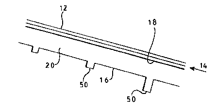
Figure '1 is a sectional side elcwatiorx, of a first embodiment of x systom
accordiztg to the
present invention and
Figure 2 is a view sisriilar to that of Figure 1 of a second preferred
~nbodzrneat of a system
'?0 accv;~ding tc~ the present invention arid
FigtirE 3 is s plan view of the system o~Figure ~.
Referring FZrst to Figure I, this shows a system for conri'vlling tar
re,guiating the flow of
AMENDED SHEET

CA 02332602 2000-11-16
covses3.wo
water down a slope. The system has a srcface layer 12 which is a pezzn~eable
layer to allov~~
liquid such as rain .water to nm through into a channel I4 formed by a
contaturao.ent layer 16.
Beriveen, the surface layer 1? and tlz;. cantaynment layer ? 6 there is a
substrate IxyEr 20. In
!he embodiment of fi gyre 1, there is additionally a dispersing layer I S tQ
aid water dispersion.
The arrazige~ent oFla3~~ers is described in detail ira Euxapean Fateut No tl
78~ 034.
~n the system shown in Figtare 1, a number of treuche;, Sfl are pzovided
wbi.ch extend
ganeratly along contour lines of the slope. )~h trench is typically U.5 rn
deep by 0.5 rn twidc
arid the trenches are typically spa~ce~ at 10 m intervals. A trench having
these dxmeaasions
will hold the e~ivatez~t o~ 7.5 mrn raiafasl frazn a i 4rn paverxzent,
assuria,iug 3Q% vozd i:~ the
I4 su'bbase stone. The tower most tech is converueritly i .4 xn deep to avoid
tb.e risk of s't3rface
floodirg if the soil infiItratiozx rate is greater than 10 'Smls.
Fignlre 2 is a vzew similar xc~ that of Figzxe 1 of a similar system in,
vc~hich the coxttainmerrt
layer is form~i by a water impervious membrane. Barriers 60 are provided at
intea-vals d4wn
the slope, the bardezs ex;ending along contv~ur lines of the slope. The
barxiers are
~S Conveniently 2t re~~ttar intervals and typically at 9 m or 10 rn intervals.
The barriers b0 ate
iii the form of u.pstands and are convez~:ez~tly formed by folds in th.e
z~t~etrrlx~rane 16, stapled
along dze top edgo and held up by steel pins.
Figure 3 is a plan view and snows that'~e barriers 60 are provided with gaps
ox openin,g~ 62
to alla w the flaw oi"watez dawn the slope. Ho~rever, the gaps or opeaaiugs
tiZ are staggered
24 t4 provide a tortuous path fvr trte water and ~sszst its dispersion.
The openings may coavezrzently he farmed by pipes, with sealed flat~ecE pipe
connectiozts
between the panels.
Alternatively, the barriers may be of more substantial caztstruotion, far
exaz~nple in the foam
of small walls covered by the membrane.
AMENDED SHEET

Representative Drawing
A single figure which represents the drawing illustrating the invention.
Administrative Status

2024-08-01:As part of the Next Generation Patents (NGP) transition, the Canadian Patents Database (CPD) now contains a more detailed Event History, which replicates the Event Log of our new back-office solution.

Please note that "Inactive:" events refers to events no longer in use in our new back-office solution.

For a clearer understanding of the status of the application/patent presented on this page, the site Disclaimer , as well as the definitions for Patent , Event History , Maintenance Fee  and Payment History  should be consulted.

Event History

Description Date
Inactive: IPC from MCD 2006-03-12
Application Not Reinstated by Deadline 2003-05-20
Time Limit for Reversal Expired 2003-05-20
Deemed Abandoned - Failure to Respond to Maintenance Fee Notice 2002-05-17
Letter Sent 2001-05-16
Inactive: Single transfer 2001-04-06
Inactive: Cover page published 2001-03-19
Inactive: First IPC assigned 2001-03-11
Inactive: Courtesy letter - Evidence 2001-03-06
Inactive: Notice - National entry - No RFE 2001-02-28
Application Received - PCT 2001-02-26
Application Published (Open to Public Inspection) 1999-11-25

Abandonment History

Abandonment Date Reason Reinstatement Date
2002-05-17

Maintenance Fee

The last payment was received on 2000-11-16

Note : If the full payment has not been received on or before the date indicated, a further fee may be required which may be one of the following

  • the reinstatement fee;
  • the late payment fee; or
  • additional fee to reverse deemed expiry.

Patent fees are adjusted on the 1st of January every year. The amounts above are the current amounts if received by December 31 of the current year.
Please refer to the CIPO Patent Fees web page to see all current fee amounts.

Fee History

Fee Type Anniversary Year Due Date Paid Date
Basic national fee - small 2000-11-16
MF (application, 2nd anniv.) - small 02 2001-05-17 2000-11-16
Registration of a document 2001-04-06
Owners on Record

Note: Records showing the ownership history in alphabetical order.

Current Owners on Record
COVENTRY UNIVERSITY
Past Owners on Record
CHRISTOPHER JOHN PRATT
Past Owners that do not appear in the "Owners on Record" listing will appear in other documentation within the application.
Documents

To view selected files, please enter reCAPTCHA code :


To view images, click a link in the Document Description column (Temporarily unavailable). To download the documents, select one or more checkboxes in the first column and then click the "Download Selected in PDF format (Zip Archive)" or the "Download Selected as Single PDF" button.

List of published and non-published patent-specific documents on the CPD .

If you have any difficulty accessing content, you can call the Client Service Centre at 1-866-997-1936 or send them an e-mail at CIPO Client Service Centre.

({010=All Documents, 020=As Filed, 030=As Open to Public Inspection, 040=At Issuance, 050=Examination, 060=Incoming Correspondence, 070=Miscellaneous, 080=Outgoing Correspondence, 090=Payment})


Document
Description 
Date
(yyyy-mm-dd) 
Number of pages   Size of Image (KB) 
Representative drawing 2001-03-18 1 6
Description 2000-11-15 3 128
Abstract 2000-11-15 1 48
Drawings 2000-11-15 1 18
Claims 2000-11-15 2 46
Description 2000-11-16 3 142
Claims 2000-11-16 2 52
Notice of National Entry 2001-02-27 1 194
Courtesy - Certificate of registration (related document(s)) 2001-05-15 1 113
Courtesy - Abandonment Letter (Maintenance Fee) 2002-06-16 1 183
Correspondence 2001-02-27 1 14
PCT 2000-11-15 16 551
PCT 2000-11-16 6 229