Note: Descriptions are shown in the official language in which they were submitted.
CA 02332906 2000-11-17
10-05-2000 GB 009901596
.. .. .... .. ..
.. .. .. . . . . . . . .
. . . . . . . . ... . . .
. . . . . . . ..
..
..~ .. .. ... .. ..
IMPROVEMENTS RELATING TO ANTI-COLLISION WARNING LIGHTS
The present invention concerns improvements relating to anti-collision warning
lights
and more specifically to a high-intensity anti-collision warning light and a
method of
driving the same for external use on aircraft.
In the field of anti-collision lights, there is a safety requirement to
provide high-
intensity regularly pulsed light on the exterior of an aircraft to enable the
aircraft to be
visible in all weather conditions. The intensity of the light is therefore
quite high
-typically being far greater than 100 Candela. Also, the flashing of the anti-
collision
light means that it is far more readily detectable than a light having a
constant
illumination. It should be noted that the flashing rate cannot be too high,
namely
above 25 Hz, because the light will be perceived by the human eye as being
continuous. Furthermore, the intensity or intensity distribution has to be
constant for
each light flash.
Existing anti-collision lights, such as those described in US patents
3,903,501 and
5,293,304, for example, use xenon flash tubes to generate the required
intensity of
light. The xenon flash tubes are driven by a discharge of an electrical
capacitance into
2o the flash tube and so driving circuits include large banks of discharge
capacitors. In
addition, xenon flash tubes have high operating voltages that are generated in
their
driving circuits by transformers stepping up voltages to the required levels.
These requirements of often large electrolytic capacitor banks and bulky
transformers
mean that the driving circuits tend to be large, heavy and expensive. This is
particularly disadvantageous when several lights and their respective driving
circuits
are provided in an aircraft where size and weight are very important issues.
In
addition, power consumption for these circuits can be undesirably high.
3o Conventional incandescent lamps that are used for aircraft navigation
lights, for
example, are far cheaper and require simpler lighter driving circuits.
However,
incandescent lamps cannot generate the high intensity of light output required
for
warning lights.
AMENDED SHEET
. CA 02332906 2000-11-17
GB 009901596
10-05-2000
. . .. .. ...... ..
~
.. . . . . . . . .
.. ..
. . . . . . . . ... . ..
. . . . . . . ..
..
..2 .. .. ... .. ..
It is desired to overcome at least some of the problems described above and to
provide
an alternative to existing high-intensity warning light technology.
The present invention resides in the appreciation that light emitting diodes
can be used
to replace xenon flash tubes in anti-collision warning lights for aircraft,
and can be
appropriately controlled to generate the required high-intensity light output.
Under
normal operation, light emitting diodes cannot generate the required light
intensity
levels -and previously this has mitigated against the use of light emitting
diodes in
. high-intensity light output applications. However, the inventors of the
present
invention have determined that by overdriving a plurality of light emitting
diodes with
a pulsed control signal, the light output can be dramatically increased
without
overheating or otherwise damaging the light emitting diodes.
According to one aspect of the present invention, there is provided an anti-
collision
warning light for external use on an aircraft, the anti-collision warning
light
comprising: a light source having a plurality of light emitting diodes which
are
arranged to be pulsed with an overdriving signal to produce a higher than
nomnal
intensity flashing light output; and means for generating the overdriving
signal, the
2o signal comprising a sequence of drive pulses, each driving pulse having a
magnitude
sufficient to cause said relatively high-intensity flashing light output, the
light source
and the generating means being arranged such that in use the intensity of the
generated
light flashes is constant and is at least 100 Candela per flash.
The use of light emitting diodes obviates the need for large banks of
capacitors and
bulky transformers that are required for driving the xenon flash tubes. The
driving
circuit of the present invention can be realised in a simple control circuit
that
generates the required series of drive pulses at a relatively low voltage.
Accordingly,
the control circuit can be significantly smaller, lighter and cheaper than
that of the
3o prior art anti-collision warning lights and also has far lower power
consumption. This
latter aspect is particularly advantageous as aircraft lights are mostly
operated from a
rechargeable battery power supply.
AMENDED SHEET
CA 02332906 2000-11-17
GB 009901596
10-05-2000
.. .. .... .. ..
.. .. .. . . . . . . . .
. . . . . . . . ... . . .
. . . . . . . ..
..
..3 .. .. ... .. ..
Another significant advantage of using light emitting diodes in place of xenon
flash
tubes is that the light emitting diodes need to be replaced far less
frequently than flash
tubes. For example, xenon flash tubes last a few hundred flying hours whereas
light
emitting diodes can last tens of thousands of flying hours. The longer
operational life
and greater reliability of light emitting diodes (light emitting diodes are
less likely to
malfunction than xenon flash tubes) can also provide significant cost savings
in the
long term. This is not only because of reduced costs of replacement components
but
more significantly because of the reduced costs of maintenance/labour.
Furthermore,
to light emitting diodes are far more robust than flash tubes with far greater
resistance to
shock and vibration. For example, the light emitting diodes of the presently
preferred
embodiment of the invention, can withstand 5000 G of force and also random
vibrations without breaking down.
Flash tubes also require shielding to prevent the electromagnetic radiation
generated
by the high-voltage transformers from affecting other equipment in the
proximity of
the warning light. A further advantage of light emitting diodes over flash
tubes is that
there is no requirement for this electromagnetic shielding because light
emitting
diodes do not require high-voltage transformers.
The generating means can be provided on the light housing to provide a self
contained
compact lighting unit. Also, the generating means is preferably configured to
be
operable in response to a received timing signal. The timing signal can be
provided by
an appropriate flash pattern box which can be positioned, for example,
remotely from
the anti-collision warning light. The flash pattern box typically includes a
microprocessor and associated memory which produce timing control signals at
an
appropriate rate which are used by the generating means to cause the light
source to
output light pulses which are perceived as regular intermittent illumination
or as a
regular sequence of light flashes.
The light emitting diodes are preferably set out in an array. This
advantageously
allows the light emitting diodes to be provided in a compact unit with a high
light
output density. In addition, the array may comprise a plurality of groups of
light
AMENDED SHEET
10-05-2000 ~ 02332906 2000-11-17 GB 009901596
.. .. .... .. ..
.. .. .. . . . . . . . .
. . . . . . . .... ..
. . . . . . : ..
..
..4 .. .. ... .. ..
emitting diodes, the groups being connected together in parallel and each
group
comprising a plurality of light emitting diodes connected in series. This
arrangement
incorporates built in redundancy which advantageously prevents catastrophic
failure
of the light emitting diode array because if one diode fails, the whole unit
will not also
fail. Rather, the series or string of diodes which contains the defective
light emitting
diode will fail and the other strings of diodes will be unaffected.
Preferably, the light emitting diodes are arranged to output a selected colour
of light
which is dependent on the. selected mode of operation. This may be achieved by
the
light emitting diodes comprising selectable sets of light emitting diodes,
each set
being capable of emitting a particular colour of light. In this way, a single
array of
light emitting diodes, for example, can generate different warning signals
depending
on the colour of the light output.
t5 A further advantage of using light emitting diodes in place of xenon flash
tubes is that
light emitting diodes generate specific narrow wavelength bands of light and
for
military aircraft applications the amount of infra-red light that is generated
can be
accurately controlled. Accordingly, the use of light emitting diodes is
inherently night
vision goggle (NVG) friendly because it does not blind pilots flying on NVGs
with
2o excess infra-red light, and also there is no need to use special filter
glass for reducing
excess infra-red light from the warning light.
The warning light may comprise a plurality of light sources. This is
advantageous
when the warning light is to provide an increased field of view in which case
each
25 source faces a different direction. For a maximal field of view, the
plurality of light
sources can be arranged about an axis to be radially outwardly facing and to
illuminate
substantially 360 degrees of view around the axis.
Preferably, the or at least one of the light sources comprises a plurality of
infra-red
30 light emitting diodes. The infra-red diodes provide a warning light which
is detectable
at night with NVGs. This is particularly for use on military aircraft during
covert
operations. The infra-red diodes are driven by a pulsed control signal in the
same
manner as the other light emitting diodes to generate the required high-
intensity light
AMENDED SHEET
CA 02332906 2000-11-17
10-05-2000 GB 009901596
- , , . .: .. .... .. .~
.. .. .. . . . . . . . .
. . . . . . . . ... . . .
. . . . . . . ..
..
..5 .. .. ... .. ..
output. When both infra-red and visible light sources are provided, the
warning light
can be switched between visible and covert operation modes. When viewed
through
NVGs the output of the infra-red light source appears identical to the visible
light w
source. This aids night vision training because this type of training can
advantageously
be carried out in daylight conditions using NVGs.
Preferably, the light output from the warning light is flashed at a rate
between 40 to
100 flashes per minute, namely 0.67 Hz to 1.67 Hz. This rate ensures that the
output
of the anti-collision warning light is relatively easy to detect visually by
observers.
to Furthermore, this rate meets the requirements for International aviation
authorities
concerning the use of the anti-collision light on an aircraft.
The drive signals from the generating means to the light source are preferably
in the
form of a rectangular shaped waveform. This waveform provides an optimal light
output over time from the light source as compared to other possible
waveforms. The
rectangular-shaped pulses preferably have a duty cycle of not more than 10%.
This
limit minimises the power consumption for the warning light whilst still
providing
sufficient on time for generating the required intensity of light output.
2o In a presently preferred embodiment of the present invention, the set
output of the
light emitting diodes is controlled by the drive pulses of the overdriving
signal being
varied to adjust the driving current supplied to each of the light emitting
diodes.
However, it is also possible to control the light output by the drive pulses
of the
overdriving signal being varied to adjust the driving voltage applied to each
of the
light emitting diodes.
According to another aspect of the present invention there is provided a
method of
driving a flashing anti-collision warning light for external use on an
aircraft, the
method comprising: pulsing a light source having a plurality of light emitting
diodes
3o with an overdriving signal to produce a higher than normal intensity
flashing light
output; and generating the overdriving signal, the signal comprising a
sequence of
drive pulses, each drive pulse having a magnitude sufficient to cause said
relatively
high-intensity flashing light output, the generating and pulsing steps being
arranging
AMENDED SHEET
. CA 02332906 2000-11-17
10-05-2000 GB 009901596
.. .. .... .: ..
s i .. .. . . . . . . . . .
. . s . . . . . ... . . . .
. , . . . . . . . . . . . .
. . . . . . . . . : . .
, ~ ~ .. .. ... .. ..
such that in use the intensity of the generated light flashes is constant and
is at least
100 Candela per flash.
According to another aspect of the present invention there is provided an anti-
collision
warning light as described above, in combination with a control means which is
arranged to control a time sequence of light flashes output from the anti-
collision
warning light. .
Preferred embodiments of the present invention will now be described by way of
i o example with reference to the accompanying drawings. In the drawings:
Figure 1 is a side view of an anti-collision light embodying the present
invention;
Figure 2 is a cross-sectional view of the anti-collision light of Figure 1
taken through
t 5 section AA' as set out in Figure 3;
Figure 3 is an underside view of the base of the anti-collision light of
Figure 1; and
Figure 4 is a schematic block diagram of the electrical circuit employed in
the anti-
20 collision light of Figure 1.
Referring now to Figures l, 2 and 3, a presently preferred embodiment of the
invention is shown in the form of an anti-collision light 10. The anti-
collision light 10
is for use on the fuselage of a military aircraft (not shown) and provides 360
degrees
25 of illumination around a central axis 12 of the light 10.
The anti-collision light 10 comprises six normally visible light emitting
diode arrays
14 which are assembled in the lower portion 16 of an aluminium central housing
18.
Eight infra-red light emitting diode arrays 20 are affixed to an upper part 22
of the
3o housing 18. Each light emitting diode array 14,20 faces radially outwardly
from the
central axis 12 so as to cover the. entire illumination range of 360 degrees.
AMENDED SHEET
CA 02332906 2000-11-17
10-05-2000 GB 009901596
, . .. .. .... .: ..
.. : . . .. . ..
. . . . . . . .... . ..
. . . . . . : :.
:.
. ~ .. .. ... .. ..
The central housing 18 is mounted on a base plate 24 and is enclosed by a
transparent
plastics cover 26. However, the cover 26 may alternatively be translucent or
made
from glass. The cover 26 allows both the generated infra-red light and the
visible light
to pass therethrough. The cover 26 can be sealed to the edges 28 of the base
plate 24
to provide a weather proof enclosure for the light emitting diode arrays
14,20.
A drive unit 30, for supplying the light emitting diode arrays 14,20 with
appropriate
driving signals, is mounted to the underside of the base plate 24. The drive
unit 30
receives timing signals from a flash pattern box (not shown) and these signals
are
l0 converted into drive signals 32 for each light emitting diode array 14,20.
The drive
signals 32 are distributed to the light emitting diode arrays 14,20 by wiring
(not
shown) between the drive unit 30 and each of the fourteen light emitting diode
arrays
14,20.
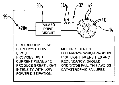
Referring now to Figure 4, the details of the drive unit operation now are
described.
For the sake of convenience, Figure 4 shows the drive unit 30 controlling a
single light
emitting diode array 14. However, it is to be appreciated that the drive unit
30 controls
each one of the light emitting diode arrays 14,20. The pulsed drive unit 30
receives its
timing signals from a remotely positioned flash pattern box which is also not
shown.
The flash pattern box is typically connected to several anti-collision lights
10 and
stores information for each anti-collision light 10 regarding the~desired
colour output,
the desired flash rate and any changes to the flash rate.
The pulsed drive unit 30 takes the timing signals from. the flash pattern box
and
z5 converts these to the drive pulses 34 for the light emitting diode array
14. Each pulse
34 is rectangular in shape and the mark/space ratio is at least 1/10. In other
words, the
duty cycle for the drive signals 32 is 10% or less. The pulses 34 are current
pulses
which have a magnitude in excess of the diode array's stated maximum current
rating.
In this embodiment, the maximum current rating for a string of light emitting
diodes is
3o SOmA and each of the drive signal pulses 34 has a magnitude of 200mA. This
generates an output which is well in excess of 100 Candela and can reach up to
1000
Candela. Accordingly, the light emitting diode array 14 is overdriven by the
drive
AMENDED SHEET
10-05-2000 ~ 02332906 2000-11-17 GB 009901596
. ~ : .. .. .... .. ~:
~ 1 ~ ~ 1 ~ ~ ~ ~ ~ ~ ~ .
1 ~ ~ ~ ~ ~ ~ ~ ~~1 ~ ~
~ 1 1 ~ ~ 1
~ ~ ~ 1 1 ~ ~ ~ . ~ 1
1 ~ ~ ~ 1 ~ ~ ~ ~ ~ ~ ~ ~ ~
signals 32 but because the signal 32 is pulsed at a rate between 0.67 Hz and
1.67 Hz,
the light emitting diode 14 does not overheat and there is no other long term
damage.
The actual light output is dependent on the power input into the light source
14.
Accordingly, the light output can be varied by changing the duty cycle of the
drive
signal 32 as well as its magnitude.
The drive unit 30 is powered by a +28 Volt power supply 36. The drive signals
32 are,
in this embodiment, output at a constant voltage of +28 Volts which is the
stated
1 o maximum operational voltage of the light emitting diode arrays. However,
in another
embodiment of the present invention, the voltage can be varied to overdrive
the light
emitting diode arrays to achieve the high-intensity light output. For example,
the
pulses 34 can be output at +30 Volts rather than +28 Volts.
I S The light emitting diode array 14 comprises a plurality of high-intensity
output light
emitting diodes 40. The light emitting diode array 14 has a plurality (24
shown in
Figure 4) of groups or strings 42 of Iight emitting diodes 40. The strings 42
are
connected together in parallel and each string 42 comprises a plurality (9
shown in
Figure 4) of light emitting diodes 40 connected in series. If one diode fails,
then the
2o string 42 to which the diode 40 belongs stops working. However, as the
other strings
42 are connected in parallel, the light emitting diodes 40 in these strings 42
continue
to function correctly. This arrangement uses the built-in redundancy to
prevent
catastrophic failure of the light emitting diode array 14 if one diode 40
fails.
25 The light emitting diode array 14 is arranged to output a selected colour
of light when
the appropriate signals are received from the drive unit 30. The array 14
comprises
sets of selectable strings 42 of light emitting diodes 40, the strings 42 of
each set are
capable of emitting a particular colour of light. In this particular
embodiment, strings
42 of light emitting diodes 40 emitting visible red light and strings 42 of
light emitting
3o diodes 40 emitting near white light are provided alternately about the
light emitting
diode array 14. The strings 42 of the red light diodes 40 are connected
together in
parallel but are not connect to the white light diodes 40. Each type of string
42 is
driven independently by the drive unit 30 in dependence on the selected mode
of
AMENDED SHEET
CA 02332906 2000-11-17
10-05-2000 GB 009901596
~ ~ . .. ~1 ~~~~ ~. i~
~~ ~a ~~ . , . ~ ~ . . . c
~ ~ ~ ~ ~ ~ ~ ~ ~~~ . . ~
- ~ . . ~ ~ ~ ~ ~ s a .. ~
~ ~ ; ~ ~ ~ ~ ~ . : ~
~ ~ .~~ ~. ~~ ~~~ .. .~
operation. Switching between the banks of diodes is carried out under control
of the
flash pattern box. However, this can also be carried out by regulating a
control voltage
within a switch box (not shown) in the cockpit.
The diode array 14 is a single unit with each diode and its interconnections
forming an
integrated circuit at the surface of a substrate. The substrate is made from a
ceramic
material which is supported on an aluminium base. For generating white light,
the
diodes comprise sapphire crystal coated with a phosphor.
to . Having described particular preferred embodiments of the present
invention, it is to be
appreciated that the embodiments in question are exemplary only and that
variations
and modifications such as will occur to those possessed of the appropriate
knowledge
and skills may be made without departure from the spirit and scope of the
invention as
set forth in the appended claims. For example, it is not necessary to have
light
emitting diode arrays covering 360 degrees of viewing angle. Rather, for
forward anti-
collision lights which require a narrower field of view, the light emitting
diode arrays
need only cover a smaller angle. Also, it is not necessary to provide the
infra-red light
emitting diode arrays 20, for commerciaUcivil aircraft for example. The light
emitting
diodes 40 can all be of the same type producing a light output of a single
colour for a
2o dedicated warning light, for example a visible white anti-collision light
or a visible red
anti-collision light. It is also not necessary for the diode arrays 14,20 to
be circular,
they can be any desired shape for example square shaped.
AMENDED SHEET