Language selection

Search

Patent 2332951 Summary

Third-party information liability

Some of the information on this Web page has been provided by external sources. The Government of Canada is not responsible for the accuracy, reliability or currency of the information supplied by external sources. Users wishing to rely upon this information should consult directly with the source of the information. Content provided by external sources is not subject to official languages, privacy and accessibility requirements.

Claims and Abstract availability

Any discrepancies in the text and image of the Claims and Abstract are due to differing posting times. Text of the Claims and Abstract are posted:

  • At the time the application is open to public inspection;
  • At the time of issue of the patent (grant).
(12) Patent: (11) CA 2332951
(54) English Title: TILTABLE LIGHT-ARC FURNACE
(54) French Title: FOUR A ARC BASCULANT
Status: Expired and beyond the Period of Reversal
Bibliographic Data
(51) International Patent Classification (IPC):
  • F27B 03/08 (2006.01)
  • C21C 05/52 (2006.01)
  • F27B 03/06 (2006.01)
  • F27B 03/10 (2006.01)
  • F27D 11/08 (2006.01)
(72) Inventors :
  • FUCHS, GERHARD (Germany)
(73) Owners :
  • ARCMET TECHNOLOGIE GMBH
(71) Applicants :
  • ARCMET TECHNOLOGIE GMBH (Austria)
(74) Agent: ROBIC AGENCE PI S.E.C./ROBIC IP AGENCY LP
(74) Associate agent:
(45) Issued: 2005-03-15
(86) PCT Filing Date: 1999-05-21
(87) Open to Public Inspection: 1999-12-02
Examination requested: 2001-05-28
Availability of licence: N/A
Dedicated to the Public: N/A
(25) Language of filing: English

Patent Cooperation Treaty (PCT): Yes
(86) PCT Filing Number: PCT/EP1999/003523
(87) International Publication Number: EP1999003523
(85) National Entry: 2000-11-22

(30) Application Priority Data:
Application No. Country/Territory Date
198 23 226.8 (Germany) 1998-05-25

Abstracts

English Abstract


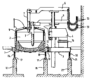
The invention relates to a tiltable light-arc
furnace in which a furnace casing (2) and a
portal (4) for an electrode lifting and pivoting
device are positioned on a platform (1 and 3)
of a weighing machine which can be tilted by
means of a tilting device. The weighing machine
comprises two rockers (16) which are situated at
a distance from each other and each move on a
track (17). The furnace casing (2) is positioned
on a first platform area situated between the
rockers (16) and the portal (4) is arranged on a
second platform area situated outside the rockers
(16). According to the invention the two platform
areas are configured as separate platform parts
(1, 3) which are connected by means of a hinge
joint (13). The platform part (3) carrying the
portal (4) is supported on an additional track
(21 ) via a further rocker (20) and by means of
a tilting device can be tilted synchronously with
the platform part (1) carrying the furnace casing
(2).


French Abstract

L'invention concerne un four à arc basculant dans lequel une carcasse de four (2) et un portique (4) pour un dispositif de levage et de pivotement d'électrode sont placés sur une plateforme (1 et 3) d'une bascule pouvant basculer au moyen d'un dispositif de basculement, ladite bascule comprenant deux barres (16) placées à distance l'une de l'autre et se déplaçant sur une voie (17). La carcasse (2) est placée sur une première zone de plateforme située entre les barres (16), et le portique (4) est placé sur une deuxième zone de plateforme située à l'extérieur des barres (16). Les deux zones de plateforme se présentent sous la forme de parties de plateforme (1, 3) séparées, reliées entre elles par l'intermédiaire d'une articulation de charnière (13). La partie de plateforme (3) supportant le portique (4) prend appui sur une autre voie (21) par l'intermédiaire d'une autre barre (20) et peut basculer par l'intermédiaire du dispositif de basculement avec la partie de plateforme (1) supportant la carcasse (2).

Claims

Note: Claims are shown in the official language in which they were submitted.


WHAT IS CLAIMED IS:
1. A tiltable arc furnace in which a furnace vessel
(2) and a portal (4) for an electrode lifting and pivoting
apparatus are arranged on a platform (1, 3) of a furnace
cradle which is tiltable by means of a tilting apparatus
and which includes three mutually spaced parallel cradle
runner skids (16, 20) which each run on a respective
support path (17, 21), wherein the furnace vessel (2) is
arranged on a vessel platform portion (1) which is between
two cradle runner skids (16) and the portal (4) is arranged
on a separate portal platform portion (3) which is outside
said cradle runner skids (16) and which is tiltable by the
tilting apparatus synchronously with the vessel platform
portion (1) carrying the furnace vessel (2), characterized
in that the two platform portions (1, 3) are connected
together by at least one hinge pivot (13) whose axis of
rotation (19) extends parallel to the intersection line
between a platform plane and the plane in which a cradle
runner skid (16, 20) lies.
2. An arc furnace as set forth in claim 1,
characterized in that besides the electrode lifting and
pivoting apparatus the portal platform portion (3) also
carries a cover lifting and pivoting apparatus.
3. An arc furnace as set forth in claim 1 or 2,
characterized in that the platform portions (1, 3) have
mutually facing edge sides (26, 27) with lower edges (24,
25) and upper edges (37, 38) and at least one hinge pivot
7

(13) is arranged adjacent to the lower edges (24, 25) of
the platform portions (1, 3).
4. An arc furnace as set forth in any one of claims
1 to 3, characterized in that the hinge pivot (13) is
formed by mutually interengaging plate-shaped projections
(30, 31) which are provided with eyes (28, 29) and which
are mounted to the mutually facing edge sides (26, 27) of
the platform portions (1, 3) and are connected together
rotatably by pivot pins (32).
5. An arc furnace as set forth in any one of claims
1 to 4, characterized in that arranged at the mutually
facing edge sides (26, 27) of the platform portions (1, 3)
in adjacent relationship to the upper edges (37, 38) is at
least one abutment (14) which limits the rotary movement of
the hinge pivot (13) and which comprises a respective
abutment portion (35, 36) mounted to respective ones of the
mutually facing edge sides (26, 27).
6. An arc furnace as set forth in claim 5,
characterized in that said arc furnace comprises a vessel
cover (9) and when the vessel cover (9) is resting on the
furnace vessel (2) the abutment surfaces of the abutment
portions (35, 36) are at a spacing of the order of
magnitude of millimeters.
7. An arc furnace as set forth in any one of claims
1 to 6, characterized in that a lateral abutment (39, 40,
36) is provided for the purposes of centering the two
platform portions (1, 3) in the tilting direction.
8

8. An arc furnace as set forth in any one of claims
1 to 7, characterized in that one hinge pivot (13) is in
the form of a fixed mounting which prevents displacement in
the direction of the axis of rotation and one hinge pivot
is in the form of a sliding mounting which permits
displacement in the direction of the axis of rotation (19)
of the pivot pin (32).
9

Description

Note: Descriptions are shown in the official language in which they were submitted.


CA 02332951 2000-11-22
TILTABLE LIGHT ARC FURNACE
Technical field
The invention concerns a tiltable arc furnace in which a furnace
vessel and a ports( for an electrode lifting and pivoting apparatus are
arranged on a platform of a furnace cradle which is tiltable by means of a
tilting apparatus and which includes three mutually spaced parallel cradle
runner skids which each run on a respective support path, wherein the
furnace vessel is arranged on a first platform portion (vessel platform
portion) which is between two cradle runner skids and the portal is
arranged on a separate second platform portion (portal platform portion)
which is outside said cradle runner skids and which is tiltable by the tilting
apparatus synchronously with the vessel platform portion carrying the
furnace vessel.
State of the art
Of the various designs for arc furnaces, in modern furnaces the
variant having a common furnace support stage or furnace platform for
furnace vessel and portal has gained extensive acceptance. The furnace
platform therefore also carries the portal with the electrode guide
columns, the cover lifting mechanism and the associated pivoting and
drive mechanisms. The entire furnace is tiltable by means of a tilting
apparatus, for example cylinders, by way of a cradle. When that happens,
the cradle runner skids are guided on a support path. The furnace usually
has two runner skids and thus two support paths which are disposed
parallel to the direction of tilting movement on stable foundations. The
geoi~netry of the cradle and the support path determines the tilting motion
of the furnace vessel. The main support path which is between the vessel
1

i
CA 02332951 2000-11-22
and the portal has to carry between about 60% and 70% of the total
vertical load, because of the overhanging portal portion.
FR-855 303 A discloses a tiltable arc furnace in which the
overhanging part of the platform which carries the portal is supported at
the outside by a third cradle sector so that the continuous cradle platform
is supported on three parallel cradle sectors. That results in a statistically
indefinite application of load.
Special machines are required to machine the bearing seat for the
portal for that machining operation can only be effected after the welding
1o procedure, because of the possibility of distortion.
During operation of the furnace distortion can occur because of the
different effects of heat acting on the arrangement and stresses within the
platform. That for example has an adverse influence on the correctness of
the electrode travel paths and the regulation thereof. Correction of the
distortion is not possible without expensive and time-consuming
dismantling of the vessel, portal and platform.
In the modernization of existing furnaces, it becomes necessary to'
install a fresh portal for better and faster electrode regulation. Aligning
and adapting the platform is then very complicated and expensive.
German published specification (DE-AS) No 11 08 830 discloses a
tiltable arc furnace in which the electrode portal is arranged on a cradle
which is separate from the furnace cradle and which can either be coupled
to the furnace cradle by a first bolt - that is intended for the small tilting
movements in the slag tapping operation - or which can be fixed to a
stationary mounting by means of a second bolt. The last-mentioned
possibility is provided in order to ensure that, when implementing major
tilting movements of the furnace vessel, in the tapping operation, the
electrodes do not also have to be tilted, which results in electrode
fractures. For the tapping operation therefore the electrodes are
previously drawn from the vessel and the separate cradle is fixed to the
stationary mounting by means of the second bolt.
2

CA 02332951 2004-03-08
Statement of the invention
According to the present invention there is
provided a tiltable arc furnace in which a furnace vessel
and a portal for an electrode lifting and pivoting
apparatus are arranged on a platform of a furnace cradle
which is tiltable by means of a tilting apparatus and which
includes three mutually spaced parallel cradle runner skids
which each run on a respective support path, wherein the
furnace vessel is arranged on a vessel platform portion
l0 which is between two cradle runner skids and the portal is
arranged on a separate portal platform portion which is
outside said cradle runner skids and which is tiltable by
the tilting apparatus synchronously with the vessel
platform portion carrying the furnace vessel, characterized
in that the two platform portions are connected together by
at least one hinge pivot whose axis of rotation extends
parallel to the intersection line between a platform plane
and the plane in which a cradle runner skid lies.
Preferably, in accordance with the invention a
20 tiltable arc furnace of the kind set forth in the opening
part of this specification is designed in such a way that
the two platform portions are connected together by at
least one hinge pivot whose axis of rotation extends
parallel to the intersection line between a platform plane
and the plane in which a cradle runner skid lies.
The structure according to the invention can be implemented in
existing furnaces if for example the portal has to be renewed. The
stoppage times can then be substantially reduced. It is also possible
without any problem firstly to convert the platform with the portal and
3o then, at a later moment in time, to convert the platform with the furnace
3

CA 02332951 2004-03-08
vessel. If the configuration according to the invention is embodied in a
fresh installation, the subsequent replacement of portal andjor vessel is
substantially easier.
An additional tilting apparatus can be mounted to the portal
platform, the additional tilting apparatus operating synchronously with the
main tilting apparatus.
Brief description of the drawings
The arc furnace according to the invention is described in greater
detail hereinafter by means of an embodiment with reference to six
Figures in which:
to Figure 1 is a plan view of a tiltable arc furnace,
Figure 2 is a partly sectional front view of the arc furnace,
Figure 3 shows a perspective view of the connection of the platform
portions,
Figure 4 shows a perspective view of a part of the vessel platform
portion, .
Figure 5 is a front view of a part on an enlarged scale partly in
section showing the connection between the two platform portions by a
hinge pivot, and
3a

CA 02332951 2000-11-22
Figure 6 is a plan view of a part on an enlarged scale of the
abutment and the guide between the two platform portions.
Ways of carying out the invention
In the Figures reference numeral 1 denotes the vessel platform
portion on which the furnace vessel 2 is arranged, and reference numeral
3 denotes the portal platform portion on which the portal 4 is arranged.
The axis of rotation 5 of the portal 4 is arranged in eccentric relationship
with the electrode carrier arms 6 which carry the electrodes 7. Reference
numeral 8 represents a separate pin for lifting and pivoting out the vessel
cover 9. Reference number 10 denotes the working door and reference
numeral 11 denotes an eccentric bottom tapping. The platform portions 1
and 3 are separated by a gap 12 and connected by hinge pivots 13.
Reference numeral 14 denotes an abutment.
The front view shown in Figure 2 additionally reveals the mounting
15 for the portal, as well as the two cradle runner skids 16 with the
associated support paths 17 for the vessel platform portion 1 which are
fixed on foundations 18. The portal platform portion 3 is supported on
one of the cradle runner skids 16 and a further cradle runner skid 20 with
a support path 21. The support path 21 is carried on a foundation 22.
2o Reference numeral 23 denotes flexible cables for the supply of power.
The perspective view in Figure 3 shows the configuration and
arrangement of the hinge pivots 13 and the position of the abutment 14.
The axis of rotation 19 of the hinge pivots 13 extends parallel to the
intersection line between a platform plane, that is to say for example the
plane formed by the top side of the vessel platform 1, and the plane in
which a cradle runner skid 16 or 20 is disposed. With linear support paths
17 and 21 therefore the axis of rotation 19 extends parallel to those
support paths when the platform is in the horizontal position. .
Figures 3 through 5 show that the hinge pivots 13 are arranged
adjacent to the lower edges 24 and 25 respectively of the mutually facing
edge sides 26 and 27 respectively of the platform portions 1 and 3
4

CA 02332951 2000-11-22
respectively. The hinge pivots 13 are formed by interengaging plate-
shaped projections 30 and 31 respectively which are provided with eyes
28 and 29 respectively and which are mounted to the mutually facing
edge sides 26 and 27 respectively of the platform portions 1 and 3
respectively and are rotatably connected together by pivot pins 32.
In the illustrated embodiment the two hinge pivots 13 are provided
in the outer regions of the edge sides 26 and 27, that is to say in the
proximity of the sides 33 and 34 of the edge sides, while the abutment 14
is disposed in the central region. As Figures 5 and 6 show, the abutment
14 is formed by oppositely disposed abutment portions 35 and 36 whose
abutment surfaces are at a spacing of between 1 and 2 mm in operation
of the furnace, that is to say when the vessel cover 9 is disposed on the
furnace vessel 2. That gap ensures a statistically defined distribution of
load to the three foundations by way of the three cradle runner skids 16
and 20. The abutment 14 is provided to restrict the flexural deflection
caused when the vessel cover 9 is lifted by virtue of the displacement of
the load onto the portal platform portion 3. The abutment 14 is disposed
adjacent to the upper edges 37 and 38 respectively of the mutually facing
edge sides 26 and 27 of the platform portions 1 and 3 approximately in
2o the central region of the edge sides 26 and 27 respectively.
The entire platform can be tilted by means of a tilting apparatus
(not shown in the drawings) which engages the vessel portal portion 1. In
that case the pivot pins 32 of the hinge pivots 13 must transmit the forces
which are required for also tilting the portal platform portion 3. In that
case and also in the tilted condition, forces are operative in the hinge pivot
in the axial direction of the pivot pins. The hinge pivots 13 are therefore
of such a configuration that the plate-shaped projections 31 engage into
plate-shaped projections 30 which are arranged in pairs. It will be
appreciated in that case that differences in thermal expansion of the
3o vessel platform portion 1 and the portal platform portion 3 mean that it is
necessary to take account of corresponding play in the axial direction of
5

CA 02332951 2000-11-22
the pivot pins 32. Preferably only one of the two hinge pivots is in the
form of a so-called fixed mounting, that is to say a mounting in which
displaceability is prevented in the axial direction of the pivot pin 32 while
the other hinge pivot is in the form of a sliding mounting in which
movement is not restricted in the axial direction of the pivot pin 32.
In the described embodiment the relative position of the two
platform portions is fixed in the axial direction of the pivot pins 32 by side
abutments 39 and 40 between which the engagement portion 36 engages.
As the guidance action implemented by means of the side abutments 39
to and 40 and the abutment portion 36, as between the platform portions 1
and 3, is in the center between the platform portions, different variations
in length in the event of different thermal loadings on the two platform
portions have a minimum effect here. The guide arrangement can thus be
set with a very small clearance of a few tenths of a millimeter. Adjusting
plates 41 serve to adjust the clearance and also the spacing between the
abutment portions 35 and 36.
The described embodiment has only one tilting apparatus in the
region of the vessel platform 1 so that the portal platform 3 also has to be
tilted by way of the hinge pivots 13 and the guide arrangement by virtue
of the side abutments 39 and 40. It is also possible to provide a further
auxiliary tilting apparatus which engages the portal platform portion 3. In
that case synchronous actuation of the two tilting apparatuses must be
ensured.
6

Representative Drawing
A single figure which represents the drawing illustrating the invention.
Administrative Status

2024-08-01:As part of the Next Generation Patents (NGP) transition, the Canadian Patents Database (CPD) now contains a more detailed Event History, which replicates the Event Log of our new back-office solution.

Please note that "Inactive:" events refers to events no longer in use in our new back-office solution.

For a clearer understanding of the status of the application/patent presented on this page, the site Disclaimer , as well as the definitions for Patent , Event History , Maintenance Fee  and Payment History  should be consulted.

Event History

Description Date
Inactive: Correspondence - MF 2010-08-10
Time Limit for Reversal Expired 2010-05-21
Letter Sent 2009-05-21
Inactive: IPC from MCD 2006-03-12
Grant by Issuance 2005-03-15
Inactive: Cover page published 2005-03-14
Pre-grant 2004-12-15
Inactive: Final fee received 2004-12-15
Notice of Allowance is Issued 2004-08-26
Letter Sent 2004-08-26
Notice of Allowance is Issued 2004-08-26
Inactive: Approved for allowance (AFA) 2004-08-17
Amendment Received - Voluntary Amendment 2004-03-08
Inactive: S.30(2) Rules - Examiner requisition 2003-09-30
Letter Sent 2001-06-22
Request for Examination Received 2001-05-28
Request for Examination Requirements Determined Compliant 2001-05-28
All Requirements for Examination Determined Compliant 2001-05-28
Inactive: Cover page published 2001-03-14
Inactive: First IPC assigned 2001-03-11
Letter Sent 2001-03-01
Inactive: Notice - National entry - No RFE 2001-03-01
Application Received - PCT 2001-02-27
Application Published (Open to Public Inspection) 1999-12-02

Abandonment History

There is no abandonment history.

Maintenance Fee

The last payment was received on 2004-04-15

Note : If the full payment has not been received on or before the date indicated, a further fee may be required which may be one of the following

  • the reinstatement fee;
  • the late payment fee; or
  • additional fee to reverse deemed expiry.

Patent fees are adjusted on the 1st of January every year. The amounts above are the current amounts if received by December 31 of the current year.
Please refer to the CIPO Patent Fees web page to see all current fee amounts.

Owners on Record

Note: Records showing the ownership history in alphabetical order.

Current Owners on Record
ARCMET TECHNOLOGIE GMBH
Past Owners on Record
GERHARD FUCHS
Past Owners that do not appear in the "Owners on Record" listing will appear in other documentation within the application.
Documents

To view selected files, please enter reCAPTCHA code :


To view images, click a link in the Document Description column. To download the documents, select one or more checkboxes in the first column and then click the "Download Selected in PDF format (Zip Archive)" or the "Download Selected as Single PDF" button.

List of published and non-published patent-specific documents on the CPD .

If you have any difficulty accessing content, you can call the Client Service Centre at 1-866-997-1936 or send them an e-mail at CIPO Client Service Centre.


Document
Description 
Date
(yyyy-mm-dd) 
Number of pages   Size of Image (KB) 
Representative drawing 2001-03-13 1 14
Description 2000-11-21 6 267
Abstract 2000-11-21 1 81
Claims 2000-11-21 2 76
Drawings 2000-11-21 5 100
Claims 2004-03-07 3 82
Description 2004-03-07 7 296
Reminder of maintenance fee due 2001-02-28 1 112
Notice of National Entry 2001-02-28 1 194
Courtesy - Certificate of registration (related document(s)) 2001-02-28 1 113
Acknowledgement of Request for Examination 2001-06-21 1 179
Commissioner's Notice - Application Found Allowable 2004-08-25 1 160
Maintenance Fee Notice 2009-07-01 1 171
PCT 2000-11-21 6 213
PCT 2000-11-22 5 141
Fees 2001-04-11 1 33
Fees 2002-05-14 1 30
Correspondence 2004-12-14 1 24
Correspondence 2010-08-09 1 46