Language selection

Search

Patent 2333002 Summary

Third-party information liability

Some of the information on this Web page has been provided by external sources. The Government of Canada is not responsible for the accuracy, reliability or currency of the information supplied by external sources. Users wishing to rely upon this information should consult directly with the source of the information. Content provided by external sources is not subject to official languages, privacy and accessibility requirements.

Claims and Abstract availability

Any discrepancies in the text and image of the Claims and Abstract are due to differing posting times. Text of the Claims and Abstract are posted:

  • At the time the application is open to public inspection;
  • At the time of issue of the patent (grant).
(12) Patent Application: (11) CA 2333002
(54) English Title: CONNECTOR FOR CONNECTING A FLUID PIPE WITHIN A SWIVEL STACK
(54) French Title: RACCORD POUR ASSEMBLER UNE CANALISATION A L'INTERIEUR D'UNE COLONNE PIVOTANTE
Status: Deemed Abandoned and Beyond the Period of Reinstatement - Pending Response to Notice of Disregarded Communication
Bibliographic Data
(51) International Patent Classification (IPC):
  • F16L 25/00 (2006.01)
  • E21B 43/01 (2006.01)
  • F16L 27/06 (2006.01)
(72) Inventors :
  • TURNER, MALCOLM E. (United States of America)
  • PERSCHKE, MALCOLM J. (United States of America)
(73) Owners :
  • FMC CORPORATION
(71) Applicants :
  • FMC CORPORATION (United States of America)
(74) Agent: FINLAYSON & SINGLEHURST
(74) Associate agent:
(45) Issued:
(86) PCT Filing Date: 1999-06-24
(87) Open to Public Inspection: 2000-01-06
Examination requested: 2000-11-22
Availability of licence: N/A
Dedicated to the Public: N/A
(25) Language of filing: English

Patent Cooperation Treaty (PCT): Yes
(86) PCT Filing Number: PCT/US1999/014449
(87) International Publication Number: WO 2000000380
(85) National Entry: 2000-11-22

(30) Application Priority Data:
Application No. Country/Territory Date
60/091,098 (United States of America) 1998-06-29

Abstracts

English Abstract


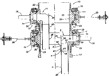
An improved product swivel (12) is disclosed which includes a connection which
connects a product pipeline (16) to an internal elbow line (34) of the
internal housing (13) of the swivel (12). A connector female or box half (42)
is welded or machined to the swivel elbow (34). The other half of the
connector pair, a pin member (46), is welded to the end of the product
pipeline (16). An installation tool and clamp (44) about the connector pair
pulls the pin (46) and box (42) together, radially expands the box (42), and
then shrinks the box (42) onto the pin (46) so that non-helical engaging teeth
(43) wedge together to produce axial tensions in the connection (40). The
connection (40) is of minimum outside diameter which advantageously reduces
the space requirement inside the swivel stack.


French Abstract

L'invention concerne une colonne de transport de produit améliorée qui comprend un raccord servant à assembler une canalisation de transport de produit et un tuyau coudé interne de l'enveloppe interne de la colonne. Un raccord femelle ou moitié de boîte est soudé ou usiné sur le tuyau coudé de la colonne. L'autre moitié de la paire de raccords, un élément de fixation, est soudé à l'extrémité de la canalisation. Un outil d'installation et collier de serrage placé autour de la paire de raccords tire l'élément de fixation et la boîte l'un à l'autre, agrandit radialement la boîte, puis rétrécit celle-ci sur l'élément de fixation pour amener des filetages conjugués non hélicoïdaux à se caler les uns aux autres afin de produire une tension axiale dans le raccordement. Ce raccordement présente un diamètre externe minimal qui réduit avantageusement le besoin en surface à l'intérieur de la colonne pivotante.

Claims

Note: Claims are shown in the official language in which they were submitted.

-6-
WHAT IS CLAIMED IS:
1. An improved product swivel which includes a cylindrical internal housing
having a longitudinal axis and a rotative swivel outer housing which is
rotatively coupled
about the outer perimeter of said internal housing, said internal housing and
said swivel outer
housing having a fluid flow path provided from said internal housing to said
swivel outer
housing, said swivel outer housing having an outlet product line which
communicates with
said fluid flow path and extends outwardly of said swivel outer housing, said
internal housing
having an inlet line which communicates at one end with said fluid flow path
and extends
inwardly into said internal housing with an elbow turn in a direction parallel
to said
longitudinal axis to a second end;
wherein the improvement comprises an internal product pipe having an outlet
end
which extends parallel to said longitudinal axis of said internal housing,
with said outlet end
of said internal product pipe facing said second end of said inlet line,
a connector having mating box and pin end portions, with one portion secured
to said
second end of said inlet line and the other portion secured to said outlet end
of said internal
product pipe,
said mating box and pin end portions having non-helical, interlocking
circumferential
teeth which are arranged and designed to mesh only when fully made up and with
said box
end portion being shrunk onto said pin end portion,
wherein said circumferential teeth are wedged together thereby producing a
high axial
preload between said box and pin end portions that maintains stiffness and
enhances fatigue
characteristics of said connector.

-7-
2. The improved product swivel wherein said box end portion is shrunk onto
said
pin end portion by placing a clamp around said pin end and box end portions,
injecting
hydraulic pressure between said pin and box end portions through a port,
thereby radially
expanding said box end portion while axially pulling said pin and box end
portions to a fully
made up position, and releasing said hydraulic pressure thereby shrinking said
box end
portion onto said pin end portion while wedging said circumferential teeth
together and
converting radial preload to high axial preload.

Description

Note: Descriptions are shown in the official language in which they were submitted.


CA 02333002 2000-11-22
WO 00/00380 PCT/US99/14449
-1-
TITLE: CONNECTOR FOR CONNECTING A FLUID PIPE WITHIN A
SWIVEL STACK
BACKGROUND OF THE INVENTION
Cross Reference to Related Application
This application claims priority from Provisional Application 60/091,098 filed
June
29, 1998.
Field of the Invention
This invention relates to a fluid swivel stack capable of transferring fluids
to and from
ships, tankers, and other sea-going vessels. In particular, it relates to a
connector for
connecting fluid pipes or risers within the fluid swivel stack for the
transfer of product to and
from the sea-going vessels to and from subsea wells.
Description of the Prior Art
A swivel stack for a floating, production, storage and offloading (FPSO)
vessel
normally has a plurality of generally vertical product risers or pipes
extending to the central
1 S body of the swivel stack from the sea floor. A swivel on the stack is
normally provided for
each fluid pipe. Generally horizontal outlet pipes or conduits extend from the
swivels to
storage areas of the FPSO vessel. The vessel weathervanes about a turret to
which the stack
body and risers are connected, and the swivels move with the vessel relative
to the swivel
stack body and risers extending within the body. The stack body which receives
the vertical

CA 02333002 2000-11-22
WO 00/00380 PGTNS99/14449
-2
risers is of a generally cylindrical shape. It is desirable to have the body
of minimal
dimensions. Elbows extend between the product pipes and annular passages in
the swivels.
Hubs and bolted flanges have commonly been employed to connect the product
pipe to the
elbows. Such hubs or flanges require space within the cylindrical body of the
swivel stack.
Summary of the Invention
The present invention is directed to a swivel stack having an inner
cylindrical body
with a plurality of swivels thereon and a plurality of vertically extending
risers or pipes
extending from subsea wells within the inner cylindrical body. Elbows extend
between the
vertical risers and swivels. An improved vertically extending connector is
provided between
each vertical riser and its associated elbow. The vertically extending
connector includes
mating female and male end portions welded to the elbow and vertical riser.
The mating
female and male end portions have non-helical, interlocking circumferential
teeth and are
assembled with a hydraulic tool which includes a hydraulic clamp and a
hydraulic pump.
After stabbing of the male and female end portions, the clamp is fitted about
the connector,
and hydraulic pressure is injected between the mating end portions which form
a pin and box
connection. The pressure expands the female (box) end portion, while the clamp
pulls the
two end portions together resulting in a wedging action of the teeth. The
wedging action of
the teeth converts radial preload into a high axial preload to maintain
connector stiffness. A
specific connector that has been found to be satisfactory may be purchased as
a "Merlin"
connector from Oil States Industries ((1K) Ltd. of Aberdeen, Scotland.
The connector of this invention (1) utilizes a minimum diameter which
minimizes the
space requirement within the swivel stack from the multiple pipes or risers
and avoids the use

CA 02333002 2000-11-22
WO 00/00380 PCT/US99/14449
_ -3-
of hubs or bolted flanges as common heretofore, (2) utilizes a minimum number
of connector
parts, and (3) may be assembled in minimal time as compared to a flanged
connection.
Other features and advantages of this invention will be apparent from the
following
specification and drawings. _
BRIEF DESCRIPTION OF THE DRAWINGS
Figure 1 is a schematic of a swivel stack showing a plurality of fluid pipes
or risers
extending within the stack from subsea wells with fluid product lines
extending from outer
swivels to storage areas on the storage vessel;
Figure 2 is an enlarged sectional view of a vertical portion of the swivel
stack
showing a pair of adjacent stacked modules, each having a swivel thereon; and
Figures 3A, 3B, and 3C illustrate stages in the creation of a connection
between a
product inlet pipe and an inlet end of an elbow of a product swivel.
DESCRIPTION OF THE INVENTION
Referring to the drawings, a swivel stack is shown generally at 10 having a
generally
cylindrical body 11 formed by a plurality of modules or sections 12 vertically
stacked on one
another with each section 12 having a body portion or inner housing 13 with a
swivel outer
housing 14 mounted thereon. A suitable product line 16 extends from each
swivel outer
housing 14 to a storage area or hold in the storage vessel. The vessel and the
swivel 14 are
designed and arranged to weathervane about the stacked inner housing 13.
Cylindrical body
outer housings 11 comprise internal interconnected housings 13 on which swivel
outer
housings 14 are rotatively mounted. The cylindrical body 26, secured to inner
housings 13, is
connected to a turret about which the vessel can rotate due to weatherwaning.
As a result,

CA 02333002 2000-11-22
WO 00/00380 PCT/fJS99/14449
swivel outer housings 14 rotate with the vessel relative to stacked body 11
upon
weathervaning of the vessel about stacked body I 1.
As shown particularly in Figure 2, vertical stack 10 includes a pair of
stacked sections
or swivels 12 stacked on one another. Of course, more than two swivels 12 may
be provided
for stack 10. Each body portion 11 of each swivel 12 is connected to a female
end portion 22
and a lower male end portion 24. Adjacent swivels 12 are connected to each
other. Body 11
which includes a plurality of connected body portions 13 has an inner
peripheral surface 26
of a predetermined internal diameter to provide space to receive vertically
extending product
pipes or risers 28 which extend downwardly to subsea wells. Bearing assemblies
29 mount
each outer swivel housing 14 for rotation relative to an associated body
portion 13 to permit
weathervaning of the vessel and body 11. An annular fluid passage 30 is
provided for each
swivel 14 and is in fluid communication with an associated product pipe 16
extending to a
suitable storage area in the storage vessel. If desired, each body portion 11
could be provided
with end flanges mating with opposed end flanges on adjacent body portions 11.
The body
portions are preferably connected together by a "Merlin" connector or
alternatively mating
flanges may be bolted together to provide a plurality of stacked swivels 12.
Elbows generally indicated at 34 are connected between risers 28 and product
pipes
16. Each elbow 34 has a horizontal portion 36 in fluid communication with
annular passage
30 and a vertical portion 38 turning at right angles to horizontal portion 36.
Vertical riser or
pipe 28 is connected to vertical portion 38 of elbow 34 by a connector
generally indicated at
40 which forms an important part of this invention. Connector 40 has a female
end portion
42 welded at 44 to vertical portion 38 and a male end portion 46 welded at 48
to vertical pipe
28. If desired, the end portions could be reversed. A connector which has been
found to be

CA 02333002 2000-11-22
WO 00/00380 PCTNS99/14449
_ -5-
advantageous is sold as a "Merlin" connector by Oil States Industries (UK),
Ltd., of
Aberdeen, Scotland.
Figures 3A, 3B, and 3C illustrate the steps in assembling female (box) end
portion 42
and male (pin) end portion 46. The connector 40 is not fully made up in the
ihustration of
connector 40 of Figure 3A. The interlocking teeth 43 are non- helical
interlocking teeth,
which because of design geometry, can mesh only when the pin and box are in
the fully
made-up position. Figure 3B shows the connection after stabbing of pin end
portion 46 into
box portion 42. A tool 44 extends about the outer periphery of connector 40. A
hose 48 is
connected to a port in the box connector 42 for application of hydraulic
pressure between the
pin 46 and the box 42. The tool pulls the pin and box, illustrated by arrows A-
A into a fully
made-up relationship as hydraulic pressure via passage 48 expands the box 42.
When
pressure is relieved, the box 42 "shrinks" onto the pin 46. Figure 3C
illustrates the
connection after the tool 44 has been removed.
The wedging action of the teeth 43 converts radial preload of the connection
into a
high axial preload to maintain the stiffness of the connector. Connector 40
presents a
minimum outside diameter, thereby minimizing the space requirement within
swivel stack 10
defined by the inner peripheral surface 26 of stack body or housing 11. The
connector 40 has
a minimal number of connector parts and is easily connected or disconnected in
a minimum
of time. The assembly as shown in Figure 3A, 3B, and 3C is accomplished in an
effective,
uncomplicated manner.
While a preferred embodiment of the present invention has been illustrated in
detail, it
is apparent that modifications and adaptations of the preferred embodiment
will occur to
those skilled in the art.

Representative Drawing
A single figure which represents the drawing illustrating the invention.
Administrative Status

2024-08-01:As part of the Next Generation Patents (NGP) transition, the Canadian Patents Database (CPD) now contains a more detailed Event History, which replicates the Event Log of our new back-office solution.

Please note that "Inactive:" events refers to events no longer in use in our new back-office solution.

For a clearer understanding of the status of the application/patent presented on this page, the site Disclaimer , as well as the definitions for Patent , Event History , Maintenance Fee  and Payment History  should be consulted.

Event History

Description Date
Inactive: IPC from MCD 2006-03-12
Application Not Reinstated by Deadline 2003-06-25
Time Limit for Reversal Expired 2003-06-25
Deemed Abandoned - Failure to Respond to Maintenance Fee Notice 2002-06-25
Inactive: Cover page published 2001-03-28
Inactive: First IPC assigned 2001-03-13
Letter Sent 2001-03-01
Inactive: Acknowledgment of national entry - RFE 2001-03-01
Application Received - PCT 2001-02-27
Request for Examination Requirements Determined Compliant 2000-11-22
All Requirements for Examination Determined Compliant 2000-11-22
Application Published (Open to Public Inspection) 2000-01-06

Abandonment History

Abandonment Date Reason Reinstatement Date
2002-06-25

Maintenance Fee

The last payment was received on 2001-03-29

Note : If the full payment has not been received on or before the date indicated, a further fee may be required which may be one of the following

  • the reinstatement fee;
  • the late payment fee; or
  • additional fee to reverse deemed expiry.

Please refer to the CIPO Patent Fees web page to see all current fee amounts.

Fee History

Fee Type Anniversary Year Due Date Paid Date
Basic national fee - standard 2000-11-22
Request for examination - standard 2000-11-22
Registration of a document 2000-11-22
MF (application, 2nd anniv.) - standard 02 2001-06-26 2001-03-29
Owners on Record

Note: Records showing the ownership history in alphabetical order.

Current Owners on Record
FMC CORPORATION
Past Owners on Record
MALCOLM E. TURNER
MALCOLM J. PERSCHKE
Past Owners that do not appear in the "Owners on Record" listing will appear in other documentation within the application.
Documents

To view selected files, please enter reCAPTCHA code :


To view images, click a link in the Document Description column. To download the documents, select one or more checkboxes in the first column and then click the "Download Selected in PDF format (Zip Archive)" or the "Download Selected as Single PDF" button.

List of published and non-published patent-specific documents on the CPD .

If you have any difficulty accessing content, you can call the Client Service Centre at 1-866-997-1936 or send them an e-mail at CIPO Client Service Centre.


Document
Description 
Date
(yyyy-mm-dd) 
Number of pages   Size of Image (KB) 
Representative drawing 2001-03-28 1 12
Cover Page 2001-03-28 1 55
Abstract 2000-11-22 1 60
Description 2000-11-22 5 216
Claims 2000-11-22 2 58
Drawings 2000-11-22 3 68
Reminder of maintenance fee due 2001-03-01 1 112
Notice of National Entry 2001-03-01 1 203
Courtesy - Certificate of registration (related document(s)) 2001-03-01 1 113
Courtesy - Abandonment Letter (Maintenance Fee) 2002-07-23 1 183
PCT 2000-11-22 6 308