Note: Descriptions are shown in the official language in which they were submitted.
CA 02333410 2000-11-24
Wb 00/23006 PCTNS99I23970
Elastic Valve With Partially Exposed Stent
Description
Backsround Art
The present invention pertains to valves and in particular to tri-leaflet
heart valve prostheses.
Ever since 1950. when blood oxygenators made open heart surgery feasible, it
has been
possible to treat some forms of heart disease by replacing one of the
patient's heart valves with a
prosthetic valve. Early heart valve prostheses included ball-and-cage valves
and disc-and-cage
valves in which a ball or a disc was housed in a cage. One side of the cage
provided an orifice
through which blood flowed either into or out of the heart, depending on the
valve being replaced.
When blood flowed in a forward direction, the energy of the blood flow forced
the ball or disc to
the back of the cage allowing blood to flow through the valve. When blood
attempted to flow in a
reverse direction, or "regurgitate", the energy of the blood flow forced the
ball or disc into the
orifice in the valve and blocked the flow of blood.
A bi-leaflet valve comprised an annular valve body in which nvo opposed
leaflet occluders
were pivotally mounted. The occluders were typically substantially rigid,
although some designs
incorporated flexible leaflets, and moved between a closed position, in which
the two leaflets were
mated and blocked blood flow in the reverse direction, and an open position,
in which the occluders
were pivoted away from each other and did not block blood flow in the forward
direction. The
energy of blood flow caused the occluders to move between their open and
closed positions.
A tri-leaflet valve comprised an annular valve body in which three flexible
leaflets were
mounted to a portion of the valve body, called a "stem," located at the
circumference of the annulus.
Some tri-leaflet valves used rigid leaflets. When blood flowed in the forward
direction, the energy
of the blood flow deflected the three leaflets away from the center of the
annulus and allowed blood
to flow through. When blood flowed in the reverse direction, the three
leaflets engaged each other
in a coaptive region, occluded the valve body annulus and prevented the flow
of blood. The valve
leaflets were made from tissue, such as specially treated porcine or bovine
pericardial tissue or from
a man-made material such as polyurethane or another biocompatible polymer.
A heart valve is implanted into an annular opening in a heart created when the
diseased valve
is removed. The valve can be secured in the annulus through the use of sutures
or pins that
penetrate the host tissue and an outside edge of the valve. Alternatively, a
sewing ring can be
attached, typically with sutures, to the elastic valve. The valve can then be
secured in the annulus
by suturing the host tissue to the sewing ring.
SUBSTIME SHEET tR~LE 26~
CA 02333410 2000-11-24
WO 00/23006 PCTNS99/23970
-2-
An important consideration in prosthetic heart valve design is the durability
of the heart
valve. Replacing a prosthetic heart valve after it has been implanted is
dangerous and expensive for
the patient and failure of a prosthetic heart valve can pause the death of a
patient. One source of
prosthetic heart valve failure is tearing of the elastic material that forms
the heart valve.
Disclosure of Invention
The invention improves the durability of elastic heart valves by eliminating
the need to
pierce the elastic material of the heart valve during construction of the
sewing ring or during
implantation.
In general, in one aspect, the invention features a valve comprising an
elastic valve body and
a stem, a first portion of the scent being embedded in the elastic valve body
and a second portion of
the stent being outside the valve body.
The invention may include one or more of the following. A sewing ring may be
coupled to
the second portion of the stent. The coupling may be provided by sutures. The
coupling may be
provided by a cloth. A coupling element may be coupled to the second portion
of the stent and the
sewing ring may comprise sewing ring fabric. The sewing ring may be coupled to
the coupling
element by wrapping the sewing ring fabric around the second element. The
valve body may
comprise an embedding layer for embedding the first portion of the scent. The
embedding layer may
comprise a first portion for embedding a peak of the scent and a second
portion for embedding a base
of the stmt. The valve body may comprise silicone. The valve body may comprise
an elastic
material and the stem may be encapsulated by the elastic material of the valve
body. The scent may
be insert molded into the valve body. The valve body may comprise molded
features that
mechanically capture the stmt.
In general, in another aspect, the invention features a valve comprising an
elastic valve
body, a stent engaged with the valve body, a sewing ring, and a coupling
between the sewing ring
and the scent.
In general, in another aspect, the invention features a method for
manufacturing a valve
comprising forming a valve body from elastic material, embedding a first
portion of a stent in the
elastic material, and leaving outside the elastic material a second portion of
the scent.
Brief Description of Drawings
Fig. 1 is a perspective view of a prior art elastic valve.
Fig. 2 is a perspective view of a prior art elastic valve implanted into
tissue.
Fig. 3 is a view of a prior art elastic valve along lines III of Fig. 2.
SUBSTIME SHE~? tRULE 26~
CA 02333410 2000-11-24
WO 00/23006 PCT/US99/23970
-3-
Fig. 4 is a perspective view of a prior art elastic valve.
Fig. 5 is a view of a prior art elastic valve along lines V of Fig. 4.
Fig. 6 is a view of a portion of a prior art elastic valve along lines V of
Fig. 4.
Fig. 7 is a view of an elastic valve according to the present invention.
Fig. 8 is a view of an elastic valve according to the present invention.
Fig. 9 is a view of an elastic valve according to the present invention.
Fig. 10 is a view of a portion of an elastic valve according to the present
invention along
lines X of Fig. 9.
Fig. 11 is a view of a portion of an elastic valve according to the present
invention along
lines X of Fig. 9.
Fig. 12 is a view of a portion of an elastic valve according to the present
invention along
lines X of Fig. 9.
Fig. 13 is a section view of a portion of an elastic valve along lines XIII of
Fig. 10.
Fig. 14 is a section view of a portion of an elastic valve along lines XIII of
Fig. 10.
Best Mode for Carrying Out the Invention
A tri-leaflet heart valve 10 comprises an annular elastic valve body 12 and
three flexible
leaflets 14 made of a biocompatible polymer such as silicone or polyurethane,
as shown in Fig. 1.
A flexible stem 16, made of metal or plastic, reinforces the elastic valve
body. In prior art valves,
the flexible stem 16 was embedded in the elastic material that formed the
valve body 12, as shown
in Fig. 1.
In some prior att designs, sutures or pins I8 were placed through an outside
edge of the
valve body 12 for attachment of the valve to the host tissue 20 as shown in
Fig. 2. The needle holes
in the valve body 12 through which the sutures 18 or pins pass are locations
for crack 22 initiation,
as shown in Fig. 3. Analysis has shown that cracks 22 can emanate from the
suture 18 or pin holes
and propagate into the leaflets 14. Such propagation will lead to incompetence
of the leaflet and
eventual structural failure of the leaflet 14.
In some prior an designs, a sewing ring 24 was coupled to the valve body 12,
as shown in
Fig. 4. The sewing ring 34 provided a point to attach the valve body 12 to
heart tissue 20. The
coupling is sometimes provided by a metal or plastic ring 26, which fits
around the outside'diameter
of the valve body 12, as shown in Fig. S. The ring 26 may be separate from the
valve body 12, as
shown in Fig. 5, or it may be part of the valve body, as shown in Fig. 6. The
ring 26 includes a
groove 28 on the side opposite the side of the ring 26 adjacent the valve body
12. A sewing cuff 30
SUBST1ME SHEET (RULE 26~
CA 02333410 2000-11-24
WO 00/23006 PCT/US99/23970
-4-
is coupled to the ring 26 by a suture windings 32 which wrap around the ring
26 and draw the
sewing cuff 30 into the groove 28 on the ring or valve body. Additional
sutures 34, 36 and 38 are
added to form the sewing cuff 30 into its final shape, shown in Fig. ~.
In coupling devices such as that shown in Fig. ~. the valve body or ring 26
have to be stiff
or they will deform allowing the sewing ring 24 to come off the valve. If the
valve body or ring 26
are not sufficiently rigid, the compressive forces placed on them when the
sutures 32 are tied tightly
down around the ring will crush them. The addition of a ring 26 will also make
the valve thicker,
thus reducing the available flow area. Further, with the n~pe of construction
illustrated in Fig. 5,
it is difficult to have a scalloped sewing ring that includes axial changes in
the location of the ring
at different rotational positions. The native annulus in the heart has this
type of scalloping, as do
tissue valves, which makes a scalloped inflow a desirable characteristic.
Finally, the type of
construction illustrated in Fig. 5 allows the sewing rind to come off the
valve if the sutures 32
securing the sewing cuff 30 to the valve body or ring 26 are cut, which is a
reported failure mode
for valves employing this kind of construction.
The invention provides a coupling between the heart tissue 20 and the valve
body 12 that
does not require the valve body to be pierced and which does not use a ring of
the sort illustrated in
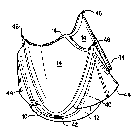
Fig. 5. This is accomplished by providing a stem 16, a first portion 40 of
which is embedded in the
valve body 12 and a second portion 42 of which is outside the valve body 12,
as shown in Fig. 7.
An embedding layer 44 is added to an outside surface of the valve body 12 near
each of the three
locations where two leaflets come together near the inside surface of the
valve, or AcommissureQa
46. The first portion 40 (which is in three segments) of the stmt is embedded
in the embedding layer
44 of the valve body 12. The second portion 42(which is in three segments) of
the scent is outside
the embedding layer 44.
In another embodiment, illustrated in Fig. 8, the bases 48 of the scent are
embedded in a base
embedding layer 50, which is added to the outside surface of the valve body
12. The peaks 52 of
the scent are embedded in the embedding layer 44. In this embodiment, the
first portion 40 of the
stem, which is embedded in the embedding layer or the base embedding layer, is
in six segments.
The second portion 42 of the scent, which is outside the embedding layer and
the base embedding
layer; is also in six segments.
A sewing ring 54 can be added to the valve body 12 as shown in Fig. 9. The
sewing ring
54 attaches to the second portion 42 of the scent 16 in the regions where the
scent 16 is outside the
suasTrrurs sH~ iRU>.~ 2~
CA 02333410 2000-11-24
WO 00/23006 PCT/tJS99123970
-5-
elastic material of the valve body 12. In the regions where the scent is
embedded in the embedding
layer 44 the sewing ring falls below the embedding layer 44.
This configuration allows the sewing ring 54 to be coupled to the valve body
12 without the
necessity of piercing the valve body 12 with sutures or pins and 'without the
need for a groove in the
valve body or ring, as shown in Figs. 10 and 11. In Fig. 10, the coupling
between the sewing ring
54 and the scent 16 is provided by sutures 56 that wrap around the scent 16
and pass through the
sewing ring 54. The sutures 5b do not pass through the embedding layer 44 or
any other part of the
valve body 12. In the region where the sutures 56 are absent, the sewing ring
54 is press fit against
the valve body 12.
The sewing ring is firmly coupled to the valve body because the stent is
embedded in the
valve body and cannot slip loose. Further, the coupling between the sewing
ring and the scent is
provided by individual sutures that do not place any compressive foree on the
stmt. Because the
scent is already present in the valve body, the coupling between the sewing
ring and the scent does
not add any thickness to the valve, leaving the flow area unaffected. Further,
the sewing ring is only
fixed where it is attached to the scent. In other areas it can follow the
scalloping of the native heart
tissue. Finally, if a suture coupling the sewing ring to the scent is cut, the
remaining sutures will keep
the sewing ring firmly attached to the stmt and thereby to the valve body.
In Fig. 11, the coupling is provided by cloth 58 that wraps around the scent
16 and the
sewing ring 54. The cloth 58 stops at the edge of the embedding layer 44.
Again, in the region
where the cloth is not present, the sewing ring 54 is press fit against the
valve body 12.
In Fig. 12, an elastic element 60 is insert molded around the exposed portion
of the stmt 16.
Sewing ring fabric 62 is wrapped around the elastic element 60 and secured by
sutures 64, which
makes the elastic element 60 the filler for the sewing ring for the exposed
portion of the stmt 16.
Again, in the region where the stem is not exposed, the sewing ring 54 is
press fit against the valve
body 12. The sutures that secure the valve to the heart tissue pass through
the sewing ring fabric
62 and the elastic element 60. The elastic element 60 is separate from the
valve body 12 so that any
cracks that form in the elastic element 60 because of the sutures will not
propagate into the valve
body 12.
A valve body according to the present invention can be manufactured by
encapsulating the
first portion 40 of the scent 16 in elastic material, as shown in Fig. 13.
during dip casting of the valve
body 12. Alternatively, the valve body 12 can be manufactured with capture
features 66 molded into
the embedding layer 44, as shown in Fig. 14. After the molding process is
completed, the scent 16
SUBSTiME SHEEP (RULE 26~
CA 02333410 2000-11-24
WO 00/23006 PCT/US99/23970
-6-
can be pressed into the embedding layer 44 of the valve body where the capture
features 66
mechanically capture it. Ocher alternatives include insert, compression or
transfer molding the stem
l6 into the embedding layer 44.
The foregoing describes preferred embodiments of the invention and is given by
way of
example only. For example, the invention is not limited to the manufacturing
techniques disclosed
but includes any manufacturing technique that leaves a portion of the stem
outside the elastic material
of the valve body. Further, the invention includes any prosthetic valve in
which the prosthetic valve
can be implanted without sutures or pins or the like piercing the elastic
material of the valve body.
The invention is not Limited to any of the specific features described herein,
but includes all
variations thereof within the scope of the appended claims.
suBSr~urs sHE~ tRU~ Zs~