Language selection

Search

Patent 2333612 Summary

Third-party information liability

Some of the information on this Web page has been provided by external sources. The Government of Canada is not responsible for the accuracy, reliability or currency of the information supplied by external sources. Users wishing to rely upon this information should consult directly with the source of the information. Content provided by external sources is not subject to official languages, privacy and accessibility requirements.

Claims and Abstract availability

Any discrepancies in the text and image of the Claims and Abstract are due to differing posting times. Text of the Claims and Abstract are posted:

  • At the time the application is open to public inspection;
  • At the time of issue of the patent (grant).
(12) Patent Application: (11) CA 2333612
(54) English Title: STRUCTURAL CONNECTION BETWEEN SWIVELS IN SWIBEL STACK
(54) French Title: RACCORD STRUCTUREL ENTRE LES TETES D'INJECTION FAISANT PARTIE D'UNE PILE DE TETES D'INJECTION
Status: Deemed Abandoned and Beyond the Period of Reinstatement - Pending Response to Notice of Disregarded Communication
Bibliographic Data
(51) International Patent Classification (IPC):
  • F16L 25/00 (2006.01)
  • F16L 13/14 (2006.01)
(72) Inventors :
  • TURNER, MALCOLM E. (United States of America)
  • PERSCHKE, MALCOLM J. (United States of America)
(73) Owners :
  • FMC CORPORATION
(71) Applicants :
  • FMC CORPORATION (United States of America)
(74) Agent: FINLAYSON & SINGLEHURST
(74) Associate agent:
(45) Issued:
(86) PCT Filing Date: 1999-06-23
(87) Open to Public Inspection: 1999-12-29
Examination requested: 2000-11-28
Availability of licence: N/A
Dedicated to the Public: N/A
(25) Language of filing: English

Patent Cooperation Treaty (PCT): Yes
(86) PCT Filing Number: PCT/US1999/014218
(87) International Publication Number: WO 1999067563
(85) National Entry: 2000-11-28

(30) Application Priority Data:
Application No. Country/Territory Date
60/090,482 (United States of America) 1998-06-24

Abstracts

English Abstract


A structural connection (3) between cylindrical housings of a swivel stack
(10) is disclosed. A connector female half (6) is welded or machined to one
end of a cylindrical housing of a product swivel (1). A pin male half (5) is
welded or machined to an end of another product swivel (1) or a base member
(2). An installation tool (7) pulls the pin (5) and box (6) together, radially
expands the box (6), and then shrinks the box (6) onto the pin (5) so that non-
helical engaging threads (20) wedge together to produce axial tension in the
connection (3). The connection (3) is structurally strong enough to act as a
structural connection (3) between product swivels (1).


French Abstract

L'invention concerne un raccord structurel (3) entre les boîtiers cylindriques d'une pile de têtes d'injection (10). Une moitié de raccord femelle (6) est soudée ou usinée à l'une des extrémités du boîtier cylindrique d'une tête d'injection (1), l'autre moitié de raccord mâle (5) étant soudée ou usinée à une extrémité du boîtier cylindrique d'une autre tête d'injection (1) ou à un élément de base (2). Un outil d'installation (7) tire l'une vers l'autre les moitiés mâle (5) et femelle (6) du raccord, élargit radialement la moitié femelle (6) puis la resserre autour de la moitié mâle (5) de manière à mettre en prise les filets non hélicoïdaux (20) afin de créer une tension axiale dans le raccord (3). Le raccord (3) possède une résistance structurelle suffisante pour servir de raccord structurel (3) entre les têtes d'injection (1).

Claims

Note: Claims are shown in the official language in which they were submitted.

-7-
SUBSTITUTE
5. As assembly for a floating storage and offloading vessel comprising:
a turret which is arranged and designed so that said vessel is capable of
weathervaning
about said turret when said turret is anchored to a seabed,
at least one riser which extends to a hydrocarbon supply on the sea floor to a
fluid
flow swivel coupled to a top end of said turret,
said swivel including a cylindrical internal housing (4), having a
longitudinal axis and
a rotatable swivel housing (1) which is rotatively coupled about the outer
perimeter of said
internal housing (4), with an internal flow path provided from said internal
housing to said
swivel housing and to said riser, said internal housing (4) being coupled to a
cylindrical
mounting base member (2) coupled to said turret,
said cylindrical mounting base number (2) and said cylindrical internal
housing (40
being secured together by a MERLIN type connector, said MERLIN type connector
providing a structural connection between said internal housing (4) and said
cylindrical
mounting base member (2) coupled to said turret.
6. The assembly of claim 5 wherein said MERLIN type connector has mating
box and pin end portions having non-helical, interlocking circumferential
teeth which are
arranged and designed to mesh only when fully made up and with said box end
portion being
shrunk onto said pin end portion, wherein said circumferential teeth are
wedged together,
thereby producing a high axial preload between said box and pin end portions
that maintains
stiffness and enhances fatigue characteristics of said connector.
7. As assembly for a floating storage and offloading vessel comprising:
a turret which is arranged and designed so that said vessel is capable of
weathervaning
about said turret when said turret is anchored to a seabed,

-8-
at least two risers which extend to hydrocarbon supplies on the sea floor to
at least
two swivel members of a fluid swivel stack coupled to a top end of said
turret,
each one of said at least two swivels having a cylindrical internal housing
having a
longitudinal axis and a rotatable swivel housing which is rotatively coupled
about the outer
perimeter of said internal housing with an internal flow path provided form
one of said two
risers through said internal housing to said swivel housing.
8. The assembly of claim 7 wherein,
said MERLIN type connector has mating box and pin end portions having non-
helical,
interlocking circumferential teeth which are arranged and designed to mesh
only
when fully made up and with said box end portion being shrunk onto said pin
end portion,
wherein said circumferential teeth are wedged together, thereby producing a
high axial
preload between said box and pin end portions that maintains stiffness and
enhances fatigue
characteristics of said connector.

Description

Note: Descriptions are shown in the official language in which they were submitted.


CA 02333612 2000-11-28
WO 99/67563 PCT/US99/14218
-1-
TITLE: STRUCTURAL CONNECTION BETWEEN SWIVELS IN
SWIVEL STACK
BACKGROUND OF THE INVENTION
Cross Reference to Related Annlication
This application claims priority from Provisional Application 60/090,482 filed
6/24/98.
Field of the Invention
This invention relates in general to a stack of rotative couplings or swivels
which are
capable of transferring fluids between the sea bed and ships, tankers, and
other sea-going
vessels. In particular, the invention relates to structural connection
arrangements for
connecting swivels together in a stack.
Description of the Prior Art
A swivel stack for a floating, production, storage and offloading (FPSO)
vessel
normally has a plurality of generally vertical product risers or pipes
extending to the central
body of the swivel stack from the sea floor. A swivel on the stack is normally
provided for
each fluid pipe which may be a manifold outlet pipe where several risers are
applied to one
manifold. Generally horizontal outlet pipes or conduits extend from the
swivels to storage

CA 02333612 2000-11-28
WO 99/67563 PCT/US99/14218
-2-
areas of the FPSO vessel. The vessel weathervanes about a turret to which the
stack body
and risers are connected, and the swivels move with the vessel relative to the
swivel stack
body and risers or manifold outlet pipes extending within the body. The stack
body or core
which receives the vertical risers is of a generally cylindrical shape. It is
desirable to
S minimize the dimensions of the stack body.
Hubs and bolted flanges have commonly been employed to connect the interior
housing of one swivel in the stack to another interior housing below or to a
base for the case
of the lower-most swivel in the stack. Such hubs or flanges require space
within the
cylindrical body of the swivel stack.
A primary objective of the invention is to provide an effective structural
connector for
connecting interior housings of swivels together to form a swivel stack while
minimizing the
height of the connection between swivels thereby minimizing the total height
of the swivel
stack.
SUMMARY OF THE INVENTION
This invention is for a swivel stack comprising a plurality of rotative fluid
couplings
(called swivels) which are structurally connected together in a stack. The
invention provides
a structural connector between the top of an inner housing of one swivel and
the bottom of an
inner housing of a second swivel stacked on top of the first connector for
each of the swivels
in the stack. Such a structural connector also connects the bottom-most swivel
to a
cylindrical base which in turn is secured to the top of a turret in a turret
mooring system. The
preferred connector for connection of the swivels together in a swivel stack
is a MERLIN TM
connector of Oil States Industries (UK) Ltd.

CA 02333612 2000-11-28
WO 99/67563 PCT/US99/14218
-3-
The connector includes mating female (box) and male (pin) end portions welded
to
the cylindrical housing bottom of a top swivel and the cylindrical housing top
of a bottom
swivel. The mating female and male end portions have non-helical, interlocking
circumferential teeth and are assembled with a hydraulic tool which is placed
inside the
connector male and female end portions. After stabbing of the male and female
end portions
of the swivels, hydraulic pressure is injected between the mating end portions
thereby
creating relative radial expansion between the male and female end portions,
with equipment
for pulling the two end portions into mating relationship. The hydraulic
pressure is relieved
and the box end shrinks about the pin end resulting in a wedging action of the
teeth. The
wedging action of the teeth converts radial preload into a high axial preload
to maintain
connector stiffness. The connector of this invention has advantages of (1)
reduced size in
outside diameter as well as height as compared to prior connection
arrangements for swivels
in a swivel stack, (2) a minimum number of connector parts (two) providing
simplicity of
design, and (3) significant time savings for make-up of each connection as
compared to
flanges or clamp style connections.
Other features and advantages of this invention will be apparent from the
following
specification and drawings.
BRIEF DESCRIPTION OF THE DRAWINGS
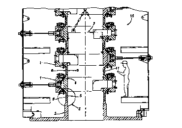
Figure 1 is a schematic of a swivel stack showing a plurality of swivels
connected
together in a stack where each swivel is structurally connected to another
swivel or to a
cylindrical base with a MERLIN TM non-rotational connector; and

CA 02333612 2000-11-28
WO 99/67563 PCTNS99/14218 ~
-4-
Figures 2A, 2B, and 2C illustrate steps for installing a MERLINrM type
connector as a structural connector between swivel cylindrical housings or a
swivel housing
and a base.
DESCRIPTION OF THE INVENTION
Figure 1 shows a plurality of swivels stacked together to form a swivel stack
10. The
inner housing of each swivel 1 is connected to the inner housing of a stacked
swivel, or to the
cylindrical housing of a base 2 by means of a connector pair 3 which is
preferably a
MERL,INTM connector available commercially from Oil States Industries (UK)
Ltd. of
Aberdeen, Scotland. Each connector pair includes a male (pin) connector half 5
and a female
(box) half 6 which have non-helical, interlocking circumferential teeth and
are assembled
with a hydraulic tool 7 and other equipment for installing MERLINTM
connectors.
Figure 1 illustrates the assembly and the method for connecting the male 5 and
female
6 parts of the connector pair 3 together. With the swivel base 2 in place, a
lower-most swivel
assembly 1 with the male portion 5 of the MERLINTM connector is lowered into
the female
portion 6 on top of the base 2. The swivel 1 is allowed to come to rest with
the MERLINTM
connector halves engaged but not connected. Hoisting equipment is removed.
Next, the connector tool 7 is lowered into the swivel stack 10. Annular
grooves 4 are
provided in the interior of the swivel housings for engagement of the internal
connector tool
7. Hydraulic pressure is injected between the teeth of the connector halves at
11 thereby
creating radial elastic expansion between the male and female portions while
allowing full
axial insertion of the male portion into the female portion by connector tool
7. Hydraulic
pressure is bled at 11 allowing the connector halves to radially contract or
"shrink" elastically
thereby providing radial wedging action of the teeth of the male and female
portions. After

CA 02333612 2000-11-28
WO 99/67563 PCT/US99/14218
-5-
the connection is made, the connection tool 7 is retrieved upwardly from
inside the swivel,
and the procedure is repeated to install successive swivels in the stack.
Figures 2A, 2B and 2C illustrate the steps in assembling female end portion 6
and
male end portion 5. The connector pair 3 is not fully made up in this
illustration of Figure
2A, but pin end 5 is stabbed into box end 6. The interlocking teeth 20 are non-
helical
interlocking teeth which, because of design geometry, can mesh only in the
fully made-up
position. Figure 2B shows the connection after a tool 7 is placed inside the
connection with
dogs 10 removably secured in grooves 4 of pin end 5 and box end 6. Hydraulic
pressure is
applied externally via port 11 for application of hydraulic pressure between
the pin 5 and the
box 6. The tool 7 pulls the pin 5 and box 6 together as illustrated by arrows
A-A into a fully
made-up relationship as the hydraulic pressure expands the box 6 and
constricts the pin 5.
When pressure is released, the box 6 "shrinks" onto the pin 5. Figure 2C
illustrates the
connection after the hydraulic tool 7 has been removed.
Structural connection of the inner housing swivels to form a swivel stack with
a
MERLIN~'M connector provides a structural connection that is simple and yet
very strong. A
great advantage of the use of the MERLINTM connector is that it reduces the
height of the
connection between swivels as compared to prior flanged type connections.
Reduced height
between each swivel translates into a reduced height of the entire swivel
stack, resulting in a
lower center of gravity of the swivel stack secured to the top of a turret in
a turret mooring
system of a vessel. A lower center of gravity reduces torque loads applied to
the turret caused
by rolling and other motions of the vessel. Lower torque loads on the turret
results in less
forces applied between the turret bearings and the vessel.
Another advantage in the connection of swivels together with a MERLINTM
connector
is that an absolute minimum of parts are used: a female half is welded to the
top of the

CA 02333612 2000-11-28
WO 99/67563 PCT/US99/14218
-6-
swivel (or base) and a male half is welded to the bottom of the swivel.
Furthermore,
significant time savings per connection are realized as compared to flange or
clamp style
connection of cylindrical members. Still another advantage is that the
MERLINrM connector
has an absolute minimum cross-section thereby reducing the weight of each
connection to a
minimum.

Representative Drawing
A single figure which represents the drawing illustrating the invention.
Administrative Status

2024-08-01:As part of the Next Generation Patents (NGP) transition, the Canadian Patents Database (CPD) now contains a more detailed Event History, which replicates the Event Log of our new back-office solution.

Please note that "Inactive:" events refers to events no longer in use in our new back-office solution.

For a clearer understanding of the status of the application/patent presented on this page, the site Disclaimer , as well as the definitions for Patent , Event History , Maintenance Fee  and Payment History  should be consulted.

Event History

Description Date
Inactive: IPC from MCD 2006-03-12
Application Not Reinstated by Deadline 2003-06-23
Time Limit for Reversal Expired 2003-06-23
Deemed Abandoned - Failure to Respond to Maintenance Fee Notice 2002-06-25
Inactive: Cover page published 2001-03-21
Inactive: First IPC assigned 2001-03-14
Letter Sent 2001-03-05
Inactive: Acknowledgment of national entry - RFE 2001-03-05
Application Received - PCT 2001-03-02
Request for Examination Requirements Determined Compliant 2000-11-28
All Requirements for Examination Determined Compliant 2000-11-28
Application Published (Open to Public Inspection) 1999-12-29

Abandonment History

Abandonment Date Reason Reinstatement Date
2002-06-25

Maintenance Fee

The last payment was received on 2001-06-04

Note : If the full payment has not been received on or before the date indicated, a further fee may be required which may be one of the following

  • the reinstatement fee;
  • the late payment fee; or
  • additional fee to reverse deemed expiry.

Please refer to the CIPO Patent Fees web page to see all current fee amounts.

Fee History

Fee Type Anniversary Year Due Date Paid Date
Request for examination - standard 2000-11-28
Registration of a document 2000-11-28
Basic national fee - standard 2000-11-28
MF (application, 2nd anniv.) - standard 02 2001-06-26 2001-06-04
Owners on Record

Note: Records showing the ownership history in alphabetical order.

Current Owners on Record
FMC CORPORATION
Past Owners on Record
MALCOLM E. TURNER
MALCOLM J. PERSCHKE
Past Owners that do not appear in the "Owners on Record" listing will appear in other documentation within the application.
Documents

To view selected files, please enter reCAPTCHA code :


To view images, click a link in the Document Description column. To download the documents, select one or more checkboxes in the first column and then click the "Download Selected in PDF format (Zip Archive)" or the "Download Selected as Single PDF" button.

List of published and non-published patent-specific documents on the CPD .

If you have any difficulty accessing content, you can call the Client Service Centre at 1-866-997-1936 or send them an e-mail at CIPO Client Service Centre.


Document
Description 
Date
(yyyy-mm-dd) 
Number of pages   Size of Image (KB) 
Representative drawing 2001-03-21 1 14
Description 2000-11-28 6 208
Abstract 2000-11-28 1 61
Claims 2000-11-28 2 71
Drawings 2000-11-28 2 60
Cover Page 2001-03-21 1 55
Reminder of maintenance fee due 2001-03-05 1 112
Notice of National Entry 2001-03-05 1 203
Courtesy - Certificate of registration (related document(s)) 2001-03-05 1 113
Courtesy - Abandonment Letter (Maintenance Fee) 2002-07-23 1 183
PCT 2000-11-28 8 319