Note: Descriptions are shown in the official language in which they were submitted.
CA 02333950 2000-11-30
WO 99/63165 PCTIIB99/00964
METHOD OF FORMING A SUPPORT STRUCTURE WITH
INTERLOCKING OF ADJACENT COMPARTMENTS
BACKGROUND OF THE INVENTION
This invention relates to a method of forming a support structure on a base,
and to a
framework for use in forming such a support structure.
It is well known to form support structures such as ro<~dways, canal or river
or bank
linings, mine packs, sea walls, or the like from a material having a honeycomb
structure, i.e having a plurality of compartments or cells divided by dividing
walls,
each compartment or cell being filled with a suitable f ller material.
Examples of
such materials for use in these support structures are Hyson-Cells from M & S
Technical Consultants & Services (Pty) Limited, Geoweb from Presto Products
Co,
CONFIRMATION COPY'
CA 02333950 2000-11-30
WO 99/63165 PCT/rB99/00964
Tenweb from Tenax Corp, Armater from Crow Company, Terracell from Webtec
Inc, Envirogrid from Akzo Nobel Geosynthetics Co and Geocells from Kaytech.
In making a support structure using these materials, it has generally been the
practice for the walls of the compartments to be substantially planar, i.e
flat, in use.
This has lead to the result that the filler material, particularly when it is
cement
based, in certain circumstances shrinks away from the walls of the
compartments
during use of the support structure, thus creating gaps in the support
structure and
reducing any support of one compartment by adjacent compartments. This in turn
results in the support structure not being able to taike as great a load as
may be
desired.
There is thus need for a method of overcoming this problem.
SUMMARY OF THE INVENTION
According to a f rst aspect of the invention there is provided a method of
forming a
support structure- on a base from a framework comprising a tube of a flexible
material divided by dividing walls of a flexible material into an array of
compartments or cells running the length of the lobe, the compartments being
arranged in rows and columns so that the tube divided by dividing walls has a
honeycomb structure, a wall or walls of each compartment including one ar more
hollow protrusions or one or more hollow recesses, or both, which method
comprises the steps of:
(1) locating the framework on the base;
(2) filling the compartments with a filler materials so that each compartment
is
adjacent to one or more other compartments fiilled with the filler material to
support and be supported by the adjacent co~mpartrnents, and so that each
hollow protrusion in a compartment wall fills with the filler material so that
each compartment protrudes into or is protruded into by at least one adjacent
compartment so as to interlock adjacent compartments.
2
CA 02333950 2000-11-30
WO 99/63165 PCTlTB99/00964
The protrusions or recesses must be of a size and shape to achieve
interlocking of
the filler material in one compartment with the filler material in an adjacent
compartment, with the common wall between the compartment still separating the
filler materials in the two compartments and thus a~;.ting as an expansion
joint. In
this way the overall strength of the support structure; formed is increased,
and there
is also increased resistance against the filler material in one compartment
being
pushed or pulled out of that compartment.
The protrusion of one compartment into another adjacent compartment allows any
load applied to the support structure to be transferred across the support
structure,
and thus assists in preventing fracture or disintegration of the support
structure,
which in turn allows the support structure to accept greater loads.
It is to be noted that a wall of a first compartment adjacent to a second
compartment
is also a wall of that second compartment, and thus that a protrusion in this
wall of
the first compartment equates to a recess in this wall of the second
compartment.
As indicated above the protrusions or recesses may have any suitable shape,
such as
for example curved or rounded shapes, a dovetail shape, a T-shape, a block
shape,
or a pyramidal shape or the like.
For certain applications, where the support structure is intended to receive a
load,
the protrusions and recesses are curved or rounded so as to allow for a degree
of
rotation between adjacent compartments during filling and setting of tt~e
filler
material, and to prevent any shearing of the protrusions from the remainder of
the
filler material in the relevant compartment on application of a load to the
support
structure.
When the protrusions and recesses are curved or rounded, each protrusion may
be
shaped substantially as a hemisphere or as a section of a sphere less than a
hemisphere. In other words the protrusion may be approximately dome shaped.
Alternatively, each protrusion may be shaped substantially as a semi cylinder
or as a
3
CA 02333950 2000-11-30
WO 99/63165 PCT/1B99/00964
section of a cylinder less than a semi cylinder. Clearly, the recesses will
nave the
complimentary shape.
In this case it is also important that the transition from the plane of the
wall to the
protrusion or recess be curved, again to prevent the ahearing of the
protrusion from
the remainder of the filler material in the relevant compartment on
application of a
load.
A wall of a compartment may include one protrusion or recess, or may include
two
or more protrusions or two or more recesses, or a combination of protrusions
and
recesses.
Each compartment may have a single wall including a protrusion or a recess, or
two
or more or all of the walls including a protrusion or a, recess.
Preferably, each wall of each compartment includes at least one protrusion or
at
least one recess.
The framework, i.e the tube and the dividing walls, may be made from any
suitable
flexible material. Although the material must possess some degree of
flexibility, the
degree of flexibility may range from very flexible up to semi rigid. The
flexible
material may be for example a plastics material such as for example a co-
extruded
or a biaxially extruded plastics material; a plastics laminate material such
as for
example a laminate of a plastics material and a metallic material or a textile
material; a metallic material; a woven or non-wovf:n textile material; a paper
or
cardboard material; and the like.
The flexible material is preferably a suitable plastics material.
The filler material may be any suitable filler material such as for example an
inert
filler material, e.g sand ox gravel or the like, or a composition comprising a
filler
material and a settable binder therefor. Examples of such compositions
include:
4
., CA 02333950 2000-11-30
WO 99/63165 PCT/1B991009b4
(i) an inert filler material such as sand or gravel or the like, and a
cementitious
binder, for example ordinary Portland Cement;
(ii) an inert filler material such as sand or gravel or the like and a
bituminous
binder;
(iii) a filler material such as soil treated with a suitable chemical
composition such
as calcium chloride, a lignin sulphonate or an ionic liquid to cause the soil
to
bind or set;
(iv) a filler material such as sand or gravel or the like and a resin binder,
for
example (a) a thermosetting resin such as polyurethanes and polyesters, {b) a
thermoplastic resin such as polyethylene, EV.A, or PVC, and (c) a suitable
wax.
The settable composition may include a conventional. foam or foaming agent so
that
the final set composition is a foamed composition, to reduce the weight
thereof.
The filler material is preferably a fluid or paste which sets into a strong,
rigid solid
conforming to the geometry of the confining compartment walls.
The filler material preferably includes a binder such as a cementitious
material, e.g
the filler material may be a concrete material having a high slump value, in
particular greater than 150, to which chemical addLitives have been added to
aid
setting.
The framework may have any suitable height and any suitable compartment size.
For example, the height of the framework may range: from 2 mm to 10 m
inclusive,
and each compartment may have a wall length of from 5 mm up to 2 m.
The compartments in the framework may have any suitable cross-section, such as
square, hexagonal or octagonal, but preferably have a square cross-section,
:i.e each
compartment is defined by four walls of substantially equal length.
CA 02333950 2000-11-30
WO 99/63165 PCT/IB99100964
The support structure may be made from a single framework as described above,
or
the support structure may be made from a plurality of frameworks laid side-by-
side
on the base, each framework being as described above and being filled with the
filler material as described above. In this case, the compartments along an
edge of
a first framework will protrude into or be protruded into by the compartments
along
an adjacent edge of an adjacent framework, to interlock the frameworks one to
another to form the support structure.
According to a second aspect of the invention there is provided a framework in
use
in forming a support structure on a base, the framework comprising a tube of a
flexible material divided by dividing walls of a flexible material into an
array of
compartments or cells running the length of the tube, the compartments being
arranged in rows and columns so that the tube divided by dividing walls has a
honeycomb structure, a wall or walls of each compartment including one or more
hollow protrusions or one or more hollow recesses or both, so that, in use,
when the
compartments are filled with a filler material, each hollow protrusion in a
compartment wall fills with the filler material so that each compartment
protrudes
into or is protruded into by at least one adjacent compartment to interlock
adjacent
compartments .
BRIEF DESCRIPTION OF THE DRAWINGS
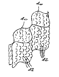
Figure 1 is a schematic perspective view of a framework of the invention;
Figure 2 is a partial perspective view of a section of a further framework
according to the invention; and
Figures 3A and 3B to 11A and 11B are cros;> sectionai views of various
compartment walls through the centre of the protrusions therein and
side views of the same compartment walls, respectively.
6
CA 02333950 2000-11-30
WO 99163165 PCTI1B99/00964
DESCRIPTION OF EMBODIMENTS
The first aspect of the invention is a method of forming a support structure
on a
base and this method will be described in more detail with reference to Figure
1.
Referring to Figure 1, there is shown a framework I O comprising a tube I2 of
a
flexible material divided by dividing walls 14 of a flexible material into an
array of
compartments 16 running the length of the tube 1:2. The compartments 16 are
arranged in rows running in the direction of the arrovv B and columns running
in the
direction of the arrow C, so that the tube 12 divided by dividing walls 14 has
a
honeycomb structure as shown.
In a first section of the framework 10, each cornp~artment 16 is defined by
four
walls. To illustrate this, we refer to the compartment. I6A which is defined
by walls
20, 22, 24 and 26. It can be seen that the wall 20 of compartment 16A also
forms a
wall of the adjacent cell 16B, the wall 22 of compartment 16A also forms a
wall of
the compartment 16C and the wall 24 of compartment I6A also forms a wall of
the
compartment 16D. The wall 26 of compartment 16A is an outside wall which may
either be the outside wall of the support structure in use, or may abut an
outside
wall of an adjacent framework 10.
For compartment 16A, the wall 20 includes a protrusion 28 (which in turn is a
recess in the compartment 16B}, the wall 22 includes a protrusion 30 (which in
turn
is a recess in the compartment 16C}, the wall 24 includes a recess 32 (which
in turn
is a protrusion in the compartment 16D) and the wall 26 includes a recess 34.
When the compartment 16A is filled with the filler material, the compartment
16A
will protrude into the compartments 16B and 16C .and will be protruded into by
compartment 16D and any adjacent compartment of an adjacent framework 10
abutting the wall 26.
In a second section of the framework I0, each compartment 16 is again defined
by
four walls, but only two of the four walls include protrusions or recesses 36.
Thus,
7
CA 02333950 2000-11-30
WO 99/63165 PCT/IB99/00964
considering the compartment 16E, it protrudes into the adjacent compartment
16F
and is protruded into by the adjacent compartment 16G, but does not protrude
into
or is not protruded into by the adjacent compartments 16H and 16I.
Nevertheless,
the compartment 16E is sufficiently interlocked witlh its neighbours to
achieve the
desired result, viz. an increase in the strength of the support structure of
which the
framework 10 forms a part. Further; when the protrusions 28, 30 32, 34 36, are
rounded, they allow any load applied to the support structure of which the
framework 10 forms a part, to be transferred across the support structure, and
thus
assist in preventing fracture or disintegration of the support structure,
which in turn
allows the support structure to accept greater loads.
The framework 10 is used to form a support structure on the base 18 as
follows.
Firstly, the framework 10 may be supported in posil:ion on the base in any
suitable
manner, for example by the use of flexible strings or rigid stays as is
disclosed in
our co-pending patent application.
Once the framework 10 is in position on the base 18, the compartments 16 are
filled
with a filler material so that the compartments 16 are: adjacent to two or
more other
compartments 16 filled with the filler material, to support and be supported)
by the
adjacent compartment 16. In addition, each protrusion 28, 30, 32, 34, 36 also
fills
with the filler material so that each compartment 16 protrudes into or is
protruded
into by at least one adjacent compartment 16 to interlock adjacent compartment
16.
As has been indicated, when each protrusion or recess is curved or rounded and
each transition between the plane of the wall and the: protrusion or recess is
curved
or rounded, this allows a degree of rotation between the blocks of filler
material in
adjacent compartments 16 during filling and settin" of the filler material.
This
rotation allows the blocks of filler material in the adjacent compartment 16
to align
so that the support structure so formed can receive a. load which is then
transferred
across the support structure. The curved or roundf;d shape of each protrusion
or
recess and transition areas also prevents any shearing of the filler material
in each
8
CA 02333950 2000-11-30
WO 99/63165 PCTl1B99/00964
protrusion or recess from the remainder of the filler material in a
compartment 16
on application of a load.
The protrusions or recesses formed in the walls of the compartment 16 may take
various shapes, some of which are illustrated in Figure 2 to 11.
Referring to Figure 2, there is illustrated two compartments 40 of a
framework,
wherein the walls of the compartments 40 include a plurality of hollow pockets
or
bubbles 42. When a filler material is placed into the compartments 4p, the
filler
material fills the pockets 42 which then press into the adjacent compartments
40 to
cause the protrusion of one compartment 40 into a.n adjacent compartment 40 to
cause, eventually interlocking of the compartments 40 in the final support
structure.
Various other protrusion shapes are illustrated in Figures 3A and 3B to 7A and
7B.
Referring to Figures 3A and 3B, a wall 50 of a corr~partment includes a
protrusion
52 which is hemispherical in shape. From Figures 3A and 3B, it can clearly be
seen that a protrusion 52 in a wall 50 of a first compartment also constitutes
a recess
in a wall 50 of a second adjacent compartment. It can also be seen that the
transition from the plane of the wall 50 to the protrusion 52, illustrated at
53, is also
curved, for the reasons stated above.
Referring to Figures 4A and 4B, a wall 54 of a compartment includes two
protrusions 56. Again each protrusion 56 is hemispherical in shape.
Referring to Figures SA and SB, a wall 58 includes a recess 60 and a
protrusion 62.
Again the protrusion 60 and the recess 62 are hemisplherical in shape.
Referring to Figures 6A and 6B a wall 64 includes a protrusion 66 which is
shaped
as a semi-cylinder which runs the width of the wall 64.
Referring to Figures 7A and 7B a wall 68 includes a protrusion 70 which is
again is
shaped as a semi-cylinder but which runs the height of the wall 68.
9
CA 02333950 2000-11-30
WO 99/63165 PCT/~B99I00964
Referring to Figures 8A and 8B a wall 72 includes a protrusion 74 which is
pyramidal in shape.
Referring to Figures 9A and 9B a wall 76 includes a protrusion 78 which is T-
shaped in cross-section.
Referring to Figures l0A and 10B a wall 80 includes a protrusion 82 which is
block
shaped.
Referring to Figures 11A and 11B a wall 84 includes a protrusion 86 which is
dovetail shape.
It is envisaged that many other types of protrusions and recesses may be
designed,
provided that the protrusions and recesses are of a sufficient size to ensure
protrusion of one compartment into an adjacent compartment to provide
interlocking.
In other words the filler material in the compartment must interlock with the
filler
material in the adjacent compartment to increase the strength of the support
structure and to provide resistance against the filler material in one
compartment
from being pushed or pulled out of the compartment. The wall between two
adjacent compartments acts as an expansion joint.
The protrusions or recesses in the walls of the compartments may be made in
any
suitable manner. For example, when the framework is made from a flexible
material which is a plastics material, the necessary protrusions or recesses
may be
formed by heating a suitably shaped tool and then pressing the heated tool
unto the
plastics material, or by vacuum moulding, or by pressing. Alternatively, when
the
flexible material of the framework is a woven or n.on-woven textile material,
the
necessary protrusions and recesses may be formed during manufacture of the
textile
material.
CA 02333950 2000-11-30
WO 99163165 PCT/IB99/00964
It has been found that a support structure made using; a framework of the
invention,
i.e one including plurality of protrusions and recesses, can support a load
which is
up to 80 % greater than an equivalent support structure made with a framework
which does not include such protrusions or recesses.
As indicated above, generally when forming a support structure, a number of
frameworks will be placed side-by-side on the base, and then each framework
will
be filled with a filler material as described. In this way, adjacent
compartments of
one framework may interlock with adjacent edge compartments of an adjacent
framework, thus providing a support structure which posseses the desired
features
of the invention, viz. protrusion of adjacent compartments into one another to
provide for interlocking and transfer of load.
The support structure formed according to the method of the invention may be
for
example a roadway or a paved area; a lining for a carnal, river, drain or
spillway or
the like; a support for an embankment; a dam or harlnour wall; or any other
suitable
support structure.
11