Note: Descriptions are shown in the official language in which they were submitted.
CA 02334150 2000-12-04
WO 99/64715 PCT/EP99/04039
- 1 -
DOViINHOLE MILLING DEVICE
Backqround of the invention
The invention relates to a device for performing
milling operations in an underground borehole. Such
milling operations may include the underreaming of the
borehole or the cutting of a window in a well tubular.
US patent specification No. 5,551,509 and
International patent application PCT/GB95/02267,
publication: number W0 96/09460, disclose the use of a
rotary milling tool which is induced to cut a window in a
well casing by pressing a rotating mill downwards along
the slant surface of a whipstock which is fixed within
the well casing at the location where the window is to be
milled. UK patent application GB 2,306,985 discloses a
mill which is pressed radially into the casing to be
milled by means of hydraulic pistons which protrude in a
radial direction from the bit motor housing and which are
actuated by the elevated pressure of the fluid which
simultaneously actuates the hydraulic bit motor. The
fluid is injected via a coiled tubing which is also used
to pull or push the mill in longitudinal direction
through the casing during the window cutting operation.
Disadvantages of the known window milling devices are
that the shape and position of the window cut thereby is
rather imprecise, that the window cutting operations are
time consuming and generate a significant amount of
sometimes coarse cuttings which are difficult to remove
from the well.
A further disadvantage of the known milling devices
is that the rotating mill exerts a high and variable
tangential torque to the device which induces the device
to run away in tangential direction. The known devices
1~ CA 02334150 2000-12-04
07-08-2000 EP 009904039
~rU - UU 1
2 _ o ?. Q 8. 2000
therefore need to be guided by guide means, such as a
whipstock, which is fixed firmly inside the casing to
avoid the device to run away during the milling
operations.
The milling device according to the preamble of
claim 1 is known from US patent 1,731,553. In the known
device a mill is driven by a shaft and complex mitre gear
wheel mechanism which is bulky and fragile and therefore
not practical for downhole use.
It is an object of the present invention to alleviate
the disadvantages of the known milling devices.
Summary of the Invention
The device according to the present invention 'thereto
comprises a flexible drive shaft as described in the
characterizing portion of claim 1.
Preferably the device is equipped with a pair of
contra-rotatable mills that exert opposite tangential
torques to the device which neutralise each other.
Such contra-rotating mills are able to cut in 'the
casing or other well tubular a well-defined window having
well-polished rims which can be sealed off easily.
Suitably the drive mechanism comprises a hydraulic
Moineau-type motor having a rotor which is rotatab.ly
mounted at the uF~per end of the stator housing and which
is secured to the upper end of the flexible drive shaft
and the pivot mechanism comprises a hydraulic piston
which is slidably arranged within the stator housing
between the outlet of the Moineau-motor and a slant upper
surface of the toppling head such that in use the
elevated pressure of the driving fluid discharged by the
motor presses the piston against said slant upper surface
of the toppling head thereby inducing the toppling head
to pivot towards t:he extended position thereof.
In that case it is preferred that the hydraulic
piston is slidabl.y arranged around the flexible shaft and
AMENDED SHEET
a~~ CA 02334150 2000-12-04
07-08-2000 EP 009904039
- 3 -
the flexible shaft is made of a resilient material and
exerts a residual torque to the toppling head which
torque induces the toppling head to pivot towards _~ts
contracted position in the absence of hydraulic pressure
exerted to the piston.
It is also preferred that if the device is used as a
casing window milling device a cuttings collecting box is
secured to the housing beneath the mills and in use the
hydraulic driving fluid emerging from the motor flushes
cuttings from the mills into the cuttings collecting box.
It is observed that European patent application
No. 0798443 describes a directional drilling assembly in
which a drill bit is driven by a shaft comprising a
cardanic coupling and that UK patent application
GB 2 311 547 discloses a downhole jetting device which
comprises a jet that is connected to a flexible hose to
allow the jet to drill a downhole sidetrack.
Brief description_of the drawings
These and other features, objects and advantages of
the milling device according to the present invention
MD09/TS6113PCT
AMENDED SHEET
CA 02334150 2000-12-04
WO 99/64715 PCT/EP99/04039
_ Q _
will be made apparent by the fol~_owing detailed
descric~ion with reference to the drawings, in whir_h:
Fia. _ is a side view of the milling device according
to the invention with a pair of mills in a retracted
position;
Fig. 2 is a schematic longitudinal sectional view of
the mil~~ing device of claim l;
Fig. 3 shows the milling device of Fig. 2 wherein the
mills are extended. and are cutting a window in a well
casing; and
Fig.-_ shows an alternative embodiment of the device
accordi::~ to the invention where the device is used as a
wellbore underream:er.
Detailec Description of the Invention
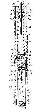
Referring to Fig. 1 there is shown a milling device
having a stator housing 1, a toppling head 2 and a pair
of contra-rotating twin mills 3 and 4. The twin mills 3
and 4 face each other at a central plane of symmetry of
the device which is orthogonal to the plane of drawing of
Fig. 1 and which intersects the plane of the drawing at
central axis 5.
The toppling head 2 is pivotably suspended within the
stator housing 1 by a pair of hinge pins 6 which permit
the toppling head 2 to rotate about an axis of rotation 7
which is substantially orthogonal to the central axis 5
and the central plane of symmetry of the device.
The toppling head 2 comprises a gear box (not shown)
having a flexible input shaft 9 and a pair of parallel
output shafts 8 which carry the mills 3 and 4 and which
are rotated relative to the toppling head 2 at equal
rotational speeds but in opposite directions, which a re
illustrated by arrows 10, in response to rotation
illustrated by arrow 12 of the flexible input shaft '7
relative tc the stator housing 1 by means of a
CA 02334150 2000-12-04
WO 99/64715 PCT/EP99/04039
- 5 -
Moineau-type or other hydraulic or electric motor (not
shown).
The r.;ilis 3 and 4 comprise substantially cylindrical
bodies on wi-:ich he:Lical cutting teeth 11 are mounteci at
similar b;:t opposite pitch angles which teeth intermesh
a t the ce:: tral plane of symmetry of the device .
When ti-m milling device is lowered through the well
the toppling head 2 and the mills 3 and 4 are in a
retracted transportation mode in which the mills 3 and 9
are substa.~,tially parallel to the central axis 5 of the
device and do not protrude from the stator housing l, as
illustrates in Fic~:~. 1 and 2. Fig. 2 shows that in the
transportat=~n mode the flexible shaft 9 obtains a curved
shape and that they toppling head 2 has a slant upper
surface 13 which has a top 19 that engages the lower end
of a piston 15 which is slidably arranged inside the
stator housing 1.
The piston 19 and slant upper surface 13 of the
toppling head together form a pivoting mechanism which
causes the toppling head 2 to rotate towards its extended
position which is shown in Fig. 3.
Fig. 3 shows that liquid discharged by the hydraulic
motor flows througr an annular opening 16 between the
upper end li of the piston 15 and the flexible shaft 9
into the interior 18 of the piston 15, as illustrated by
arrows 19.
As a result of the flow restriction of the annular
opening 16 ~ hydraulic pressure difference is created
between the cavity 20 above the piston 15 and the piston
interior 18 which induces the piston to slide downwards
through the stator. housing 1 as illustrated by arrows 21.
The downward motion of the piston also pushes the to;p 14
of the slar:t upper surface 13 of the toppling head 2
downwards wi:ich causes the toppling head 2 to pivot abbut
pivot axis - as illustrated by arrow 31.
CA 02334150 2000-12-04
WO 99/64715 PCT/EP99l04039
- 6 -
The mills 3 and 9 pivot together with the toppling
head 2 about the pivot axis '7 towards their extended
position and are simultaneously rotated by the shafts 8
and thereby mill a window 22 in a casing 23 surrounding
the device.
The outward pivoting of the mills 3 and 9 continues
until the entire ~;lant upper surface 13 of the toppling
head 2 engages the lower end of the piston 15, in which
position. the mill; 3 and 4 protrude at a predetermined
orientation from t:he stator housing 1. Liquid is
discharged from the interior 18 of the piston via an
outlet opening 24 which injects the liquid at high speed
towards the mills 3 and 4 thereby cooling the cutting
teeth 11 thereof and flushing away cuttings 25. The
liquid is then circulated through a cuttings collecting
box 26 which is suspended at the bottom of the stator
housing 1 as illu~>trated by arrows 27. A guide plate 28
in the collecting box 26 serves to reduce the speed of
the liquid so that: the cuttings are allowed to be
separated by gravity and/or magnetic forces from the
liquid and are deposited at the bottom of the box,
whereas the liquid is discharged via an opening 29 at the
top of the box 26 into the annulus surrounding the
device.
Whiie the mills 3 and 4 are cutting the window 22 in
the well casing 23 the device is pulled upwards through
the casing as illustrated by arrows 30 by means of a
piston (not shown) above the device until the window 22
has the desired length. It is preferred that the device
is suspended with_Ln the casing 23 from a coiled tubing or
drill string (not shown) and that the coiled tubing or
drill string is gradually pulled up during the milling
operations whilst the piston above the device ensures
that the device is moved up through the casing 23 at. an
CA 02334150 2000-12-04
WO 99/64715 PCT/EP99/04039
accurately defined speed and over an accurately defined
distance.
The balanced forces exerted by the mills 3 and 4 to
the stator housing allow the device to mill a straight
and well defined window in the well casing 23 in a quick
and accurate manner and without leaving cuttings in the
casing interior. It: will be understood that, if desired,
the mills may have a non-cylindrical shape, such as a
frusto-conical shape. In such case it is preferred that
the axes of rotation of the mills intersect each other at
the central plane of the device.
Fig. 4 shows an embodiment of the device according to
the invention where the device is used for underreaming
of an uncased underground borehole.
The upper part of the device shown in Fig. 4 is
similar to the upper part of the device shown in
Figs. 1-3 and similar reference numerals denote similar
components.
The device shown in Fig. 4 however contains no
cuttings collection box and has a stator housing 1 which
is rotated about the central axis 5 as is illustrated by
arrow 90.
The device of Fig. 9 is equipped with a single mill 4
which underreams the wellbore 41 as a result of the
simultaneous rotation of the stator housing and of the
mill 4 relative to the toppling head 2. The toppling
head 2 is extendecL and retracted in the same way as
described with reference to Figs. 1-3.
The flexible shaft 9 is connected to the output
shaft 8 via a gearbox in the toppling head 2, or may
alternatively be integrated with the output shaft E3. If
desired the underreamer device shown in Fig. 4 may be
equipped with a pair of contra-rotatable twin mills 4
similar to those _=sh own in Figs. 1-3.