Language selection

Search

Patent 2334275 Summary

Third-party information liability

Some of the information on this Web page has been provided by external sources. The Government of Canada is not responsible for the accuracy, reliability or currency of the information supplied by external sources. Users wishing to rely upon this information should consult directly with the source of the information. Content provided by external sources is not subject to official languages, privacy and accessibility requirements.

Claims and Abstract availability

Any discrepancies in the text and image of the Claims and Abstract are due to differing posting times. Text of the Claims and Abstract are posted:

  • At the time the application is open to public inspection;
  • At the time of issue of the patent (grant).
(12) Patent Application: (11) CA 2334275
(54) English Title: PIPE LINING
(54) French Title: REVETEMENT INTERIEUR DE CONDUITES
Status: Deemed Abandoned and Beyond the Period of Reinstatement - Pending Response to Notice of Disregarded Communication
Bibliographic Data
(51) International Patent Classification (IPC):
  • B29C 63/34 (2006.01)
  • B29C 55/00 (2006.01)
  • B29C 65/00 (2006.01)
  • F16L 55/165 (2006.01)
(72) Inventors :
  • MCGUIRE, BRIAN EDWARD (United Kingdom)
(73) Owners :
  • BG TRANSCO PLC
  • LATTICE INTELLECTUAL PROPERTY LTD.
(71) Applicants :
  • BG TRANSCO PLC (United Kingdom)
  • LATTICE INTELLECTUAL PROPERTY LTD. (United Kingdom)
(74) Agent: GOWLING WLG (CANADA) LLPGOWLING WLG (CANADA) LLP
(74) Associate agent:
(45) Issued:
(86) PCT Filing Date: 1998-06-10
(87) Open to Public Inspection: 1999-12-16
Examination requested: 2000-11-29
Availability of licence: N/A
Dedicated to the Public: N/A
(25) Language of filing: English

Patent Cooperation Treaty (PCT): Yes
(86) PCT Filing Number: PCT/GB1998/001552
(87) International Publication Number: WO 1999064222
(85) National Entry: 2000-11-29

(30) Application Priority Data: None

Abstracts

English Abstract


A lining method for a host pipe (10) including lubrication of the host pipe
prior to insertion of a thermoplastic liner (11) using tight fit techniques.
After allowing the inserted liner to relax, the liner is partially pulled from
within the host pipe using puller (20) and clamped with an internal clamp (30)
to allow fitting of a special flange (40) to the liner (11) by butt fusion,
for example. Thereafter the liner is allowed to revert so as to abut a flange
(12) fitted to the host pipe (10). The technique is repeated at the other pipe
end.


French Abstract

Procédé de revêtement intérieur pour conduite réceptrice (10), qui consiste à lubrifier ladite conduite avant d'introduire un revêtement intérieur thermoplastique (11) à l'aide de techniques d'ajustement serré. Une fois le revêtement intérieur relâché, ce dernier est partiellement tiré depuis l'intérieur de la conduite à l'aide d'un dispositif de traction (20) et serré à l'aide d'un élément de serrage interne (30) pour permettre l'adaptation d'une bride spéciale (40) sur le revêtement (11) par fusion bout à bout, par exemple. Ensuite, on laisse le revêtement rentrer dans la conduite de manière à ce qu'il vienne en contact avec une bride (12) installée sur la conduite réceptrice (10). Ladite technique est répétée à l'autre extrémité de la conduite.

Claims

Note: Claims are shown in the official language in which they were submitted.

-8-
CLAIMS
1. A method of lining a host pipe including the steps of: lubricating the
host pipe along an internal face for an elongate portion at each end of the
host
pipe;
lining the pipe with a thermoplastic liner using a tight fit technique;
allowing the inserted pipe liner to relax;
pulling a portion of the liner from the host pipe using limited force;
affixing a thermoplastic flange thereto by a sealing technique; and,
allowing the liner to revert within the pipeline so as the thermoplastic
flange
abuts a flange on the host pipe.
2. A method as claimed in claim 1, wherein the thermoplastic flange is
attached to the liner by butt fusion.
3. A method as claimed in claim 1 or 2, wherein a thermoplastic flange
is attached to each end of the liner.
4. A method as claimed in claim 1, 2 or 3 including the step of affixing
a flange to the host pipe.

-9-
5. A method as claimed in any one of claims 1 to 4, wherein the liner is
pulled from the host pipe by means of a combined puller/clamp.
6. A method as claimed in any one of claims 1 to 5, wherein the liner is
passed through a die to compress the pipe during insertion.
7. A method as claimed in any one of claims 1 to 6, wherein the liner and
flange are of polyethylene.
8. A method as claimed in any one of claims 1 to 7, including the step of
internally clamping the liner during the flange affixing step.
9. A method as claimed in any one of claims 1 to 8, including the step of
trimming the liner prior to fitting the flange.
10. A pulley device for pipe lining including fixing means for affixing the
device to a rigid pipeline flange attached to a host pipe; gripper means for
gripping a thermoplastic liner within the host pipe to allow a portion of the
liner to be pulled from within the host pipe.
11. A pulley device as claimed in claim 10, including means for holding the

-10-
liner portion pulled from the pipe to allow a thermoplastic pipe flange to be
fitted prior to release of the liner.
12. A puller device as claimed in claim 11, wherein the means for holding
the liner portion are provided as a separate element to the puller and can be
affixed internally of the liner prior to removal of the pulley device to allow
fitting of the liner flange.
13. A pulley device as claimed in claim 10, 11 or 12, wherein fluid drive
means are provided to effect the pulling of the pipe liner from the host pipe.
14. A thermoplastic pipe flange including a first portion for butt fusion to
a liner pipe and a second portion for affixing to a flanged portion of a rigid
pipe.
15. A method of lining a host pipe according to claim 1 and substantially
as described herein.
16. A pulley device for pipelining substantially as described herein and
with reference to Figure 2 of the accompanying drawings.

-11-
7. A thermoplastic pipe flange substantially as described herein and with
reference to Figure 3 of the accompanying drawings.

Description

Note: Descriptions are shown in the official language in which they were submitted.


CA 02334275 2000-11-29
WO 99/64222 PCT/GB98/01552
-1-
The invention relates to pipe lining. In pipeline systems it is known to line
them with plastic pipe for refurbishment when corrosion puts the integrity of
the existing pipe at risk or when a suitable barrier is required to prevent
corrosion occurring. The existing host pipe may be steel, cast iron, asbestos
or other rigid material. Polyethylene is typically used for the liner and
provides a corrosion barrier for the oil and petrochemical industry for
example.
To maximise the bore diameter it is preferred that the liner be a tight fit
within
the host pipe. An existing system utilises polyethylene piping which is forced
through a die to compress its overall diameter as it passes in the pipe to aid
insertion. Such a technique is employed in the Swagelining (RTM) pipelining
system.
There is established a number of other lining systems which when installed
are not tight fit liners. This in turn means that there is an annulus between
the
liner pipe and the host pipe.

CA 02334275 2000-11-29
WO 99/64222 PCT/GB98/01552
-2-
Where an annulus exists it is possible for substantial permeability to occur,
which in turn can cause pressure balancing which could lead to implosion of
the liner and consequential failure of the system.
With the Swagelining pipelining system, no annulus is present and
permeability through the Liner is thus greatly reduced.
The technical requirements for lined pipes may typically call for flanges
every
S00 metres which using non tight fit liners is achieved by drawing out the
liner at each end of a lined pipe and butt fusing a polyethylene flange
thereto;
the line then being allowed to slip back within the host pipe. It has not been
possible to deal with tight fit liners in this manner so as to allow flanges
to be
fitted.
The present invention is concerned with a mechanism for allowing flanges to
be fitted to tight fit liners, typically polyethylene, within a host pipe.
According to the invention there is provided a method of lining a host pipe
including the steps of lubricating the host pipe along an internal face for an
elongate portion at each end of the host pipe; lining the pipe with a

CA 02334275 2000-11-29
WO 99/64222 PCT/GB98/01552
-3-
thermoplastic liner using a tight fit technique; allowing the inserted pipe
liner
to relax; pulling a 'portion of the liner from the host pipe using limited
force;
affixing a thermoplastic flange thereto by a sealing technique; and allowing
the liner to revert within the pipeline so as the thermoplastic flange abuts a
flange on the host pipe.
Further according to the invention there is provided a pulley device for pipe
lining including fixing means for affixing the device to a rigid pipeline
flange
attached to a host pipe; gripper means for gripping a thermoplastic liner
within the host pipe to allow a portion of the liner to be pulled from within
the
host pipe.
Separate means may be provided for holding the liner portion pulled from the
pipe to allow the pulley device to be removed and a thermoplastic pipe flange
to be fitted prior to release of the liner.
Still further according to the invention there is provided a thermoplastic
pipe
flange including a first portion for butt fusion to a liner pipe and a second
portion for affixing to a flanged portion of a rigid pipe.

CA 02334275 2000-11-29
WO 99/64222 PCT/GB98/01552
-4-
The invention will now be described by way of example with reference to the
accompanying drawings in which:
Figure 1 shows an existing host pipe with a tight fit liner in place;
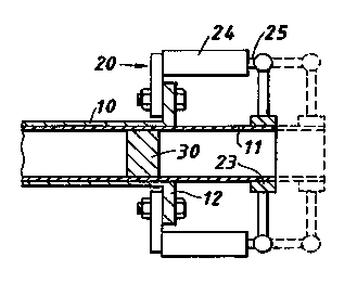
Figure 2 shows the clamp and puller mechanisms fitted; and
Figure 3 shows the cutting of the extended liner to a predetermined length and
the fitting of a fused end piece.
In existing tight fit arrangements such as the Swagelining (RTM) pipelining
system, the polyethylene pipe is forced through a die and this allows the
temporarily reduced diameter pipeliner to slide within the host pipe to the
desired length. The liner then returns to its original diameter to fit hard
against the internal surface of the host pipe. In the present invention,
modified insertion procedures are required to handle very long pipelines
which may be made up from portions of about 500 metres in length, for
example.
In the modified arrangement (see Figure 1 ), in order to carry out the lining

CA 02334275 2000-11-29
WO 99/64222 PCT/GB98/01552
-5-
procedure, a suitable pressure rated steel flange 12 is fitted to the pipeline
10
at each end which then receives the liner 11.
In the present method, however, prior to fitting the plastic tight fit lining
1 l,
the inside of the host pipe 10 is lubricated for a suitable length at each
end,
typically for 10 metres. The special lubrication is applied throughout
360°
within the liner pipe wall. The length of pipe lubricated is typically
dependent on the length of pipe to be lined. Thereafter the pipeline is lined
with a liner 11 of polyethylene or other thermoplastic material using a tight
fit technique (e.g. Swagelining (RTM) pipelining) as shown in Figure 1.
After insertion, the pipe is allowed to fully relax to fill the void and to
ensure
no longitudinal or hoop stresses are left in the liner. Once this state has
been
reached a second step is carried out as shown in Figure 2.
A liner pulling device 20 is affixed to one of the host pipeline flanges 12,
by
means of a suitable device (e.g. bolts 22). The pulley 20 also has a portion
23 which is configured to clamp and grip the inner liner 11 adjacent its end.
The gtipper is designed to exert an effort that is not more than half the
yield
of the liner material. To exert the effort a pair of hydraulic cylinders 24
have

CA 02334275 2000-11-29
WO 99/64222 PCT/GB98/01552
-6-
an extendible rod 25 limited to the gripper 23.
The end of liner under pulling action from the puller will be stretched and
due
to the lubricant will emerge from the host pipe. This action will continue
until
a sufficient length is exposed to allow a suitable flange to be fitted. An
internal clamp 30 is also provided to hold the extended liner 11 in place
whilst the puller 20 is removed and further steps are carried out. This is
fitted
after the liner is extended.
As shown in Figure 3, after the puller 20 is removed, the clamped liner is
then
trimmed to the correct predetermined length (x) and a purpose designed
polyethylene flange 40 is butt fused to the liner. This may take the form of
a thermoplastic flanged pup piece.
After the butt fused joint has cooled, the internal and external weld beads
are
removed. The expander clamp 30 can then be removed and this allows the
liner 11 to relax back into the host pipeline 10. Reversion may be assisted
by pushing the polyethylene flange 40 towards the metal pipeline flange 12.
Once the flange fitting has been completed at one end the whole process is
repeated at the other end of the liner and host pipe.

CA 02334275 2000-11-29
WO 99/64222 PCT/GB98/01552
_'7_
Under existing circumstances, with a tight fit liner, it would not have been
possible to draw the liner out without stressing the litler beyond acceptable
limits. The present arrangement, however, achieves the desired technique
without damage to the liner or causing undue stress.

Representative Drawing
A single figure which represents the drawing illustrating the invention.
Administrative Status

2024-08-01:As part of the Next Generation Patents (NGP) transition, the Canadian Patents Database (CPD) now contains a more detailed Event History, which replicates the Event Log of our new back-office solution.

Please note that "Inactive:" events refers to events no longer in use in our new back-office solution.

For a clearer understanding of the status of the application/patent presented on this page, the site Disclaimer , as well as the definitions for Patent , Event History , Maintenance Fee  and Payment History  should be consulted.

Event History

Description Date
Inactive: IPC from MCD 2006-03-12
Application Not Reinstated by Deadline 2004-06-10
Time Limit for Reversal Expired 2004-06-10
Deemed Abandoned - Failure to Respond to Maintenance Fee Notice 2003-06-10
Letter Sent 2002-07-02
Letter Sent 2002-02-14
Inactive: Single transfer 2002-01-11
Inactive: Courtesy letter - Evidence 2001-05-08
Inactive: Single transfer 2001-03-29
Inactive: Cover page published 2001-03-26
Inactive: First IPC assigned 2001-03-20
Inactive: Courtesy letter - Evidence 2001-03-13
Inactive: Acknowledgment of national entry - RFE 2001-03-09
Application Received - PCT 2001-03-07
All Requirements for Examination Determined Compliant 2000-11-29
Request for Examination Requirements Determined Compliant 2000-11-29
Application Published (Open to Public Inspection) 1999-12-16

Abandonment History

Abandonment Date Reason Reinstatement Date
2003-06-10

Maintenance Fee

The last payment was received on 2002-05-27

Note : If the full payment has not been received on or before the date indicated, a further fee may be required which may be one of the following

  • the reinstatement fee;
  • the late payment fee; or
  • additional fee to reverse deemed expiry.

Please refer to the CIPO Patent Fees web page to see all current fee amounts.

Owners on Record

Note: Records showing the ownership history in alphabetical order.

Current Owners on Record
BG TRANSCO PLC
LATTICE INTELLECTUAL PROPERTY LTD.
Past Owners on Record
BRIAN EDWARD MCGUIRE
Past Owners that do not appear in the "Owners on Record" listing will appear in other documentation within the application.
Documents

To view selected files, please enter reCAPTCHA code :


To view images, click a link in the Document Description column. To download the documents, select one or more checkboxes in the first column and then click the "Download Selected in PDF format (Zip Archive)" or the "Download Selected as Single PDF" button.

List of published and non-published patent-specific documents on the CPD .

If you have any difficulty accessing content, you can call the Client Service Centre at 1-866-997-1936 or send them an e-mail at CIPO Client Service Centre.


Document
Description 
Date
(yyyy-mm-dd) 
Number of pages   Size of Image (KB) 
Representative drawing 2001-03-26 1 7
Abstract 2000-11-29 1 43
Description 2000-11-29 7 202
Claims 2000-11-29 4 87
Drawings 2000-11-29 1 20
Cover Page 2001-03-26 1 41
Notice of National Entry 2001-03-09 1 203
Request for evidence or missing transfer 2001-12-03 1 109
Courtesy - Certificate of registration (related document(s)) 2002-02-14 1 113
Courtesy - Abandonment Letter (Maintenance Fee) 2003-07-08 1 175
Correspondence 2001-03-09 1 23
PCT 2000-11-29 12 494
PCT 2001-01-22 1 52
PCT 2001-02-19 1 51
Correspondence 2001-05-08 1 24
Correspondence 2001-12-13 3 86
Correspondence 2002-07-02 2 51
Fees 2001-05-25 1 35
Fees 2002-05-27 1 32