Note: Descriptions are shown in the official language in which they were submitted.
CA 02334286 2000-11-29
WO 99164345 PCTNS99/I2705
CONTAINER SYSTEM FOR PRESSURIZED FLUIDS
FIELD OF THE INVENTION
The present invention relates to containers for containing high-pressure
fluids and is
directed to an inexpensive, light, compact, flexible and safe container for
pressurized fluids
which is resistant to explosive rupturing.
BACKGROUND OF THE INVENTION
Containers presently used for the storage and use of compressed fluids and
particularly
gasses, generally take the form of cylindrical metal bottles wound with
reinforcing materials to
withstand high fluid pressures. Such storage units are expensive to
manufacture, inherently
heavy, bulky, inflexible and prone to fragmentation that can lead to
explosions. Such containers
are commonly used to store oxygen. By way of example, the medical use of
compressed oxygen
for ambulatory patients is growing rapidly. As another example, portable metal
tank containers
are carried by fire fighters at the scene of a fire to provide emergency air.
Synthetic plastic
containers for pressurized fluids are also presently utilized, however,
existing containers of this
type do not provide sufficient bursting strength where high fluid pressures
are encountered.
SUMMARY OF THE INVENTION
The container system for pressurized fluids embodying the present invention
overcomes
the aforementioned problems inherent to prior art pressurized fluid container
systems.
More particularly, the container system for pressurized fluids embodying the
present
' 20 invention includes a plurality of form-retaining, generally ellipsoidal
chambers having open ends
through which coaxially extends a tubular core which is sealingly secured
within the ends of the
chambers. The core serves to support the ellipsoidal chambers along the length
of the core. The
core is formed with apertures along its length, with one of such apertures
being positioned within
the confines of each ellipsoidal chamber so as to be in fluid-transfer
communication with the
interior of the ellipsoidal chambers. The apertures are of comparatively small
size so as to be
CA 02334286 2000-11-29 '
WO 99/64345 PCT/US99/IZ705
2 ,
able to control the rate of evacuation of pressurized fluid from the
ellipsoidal chambers.
Accordingly, if one or more of the ellipsoidal chambers are punctured, the
pressurized fluid
contained therewithin must escape from all of the chambers through the core
apertures, thus
causing the pressurized fluid to maintain its inertia of internal mass because
of the resistance
provided by the comparatively small apertures. A very low fluid evacuation
rate is thereby
effected so as to avoid a large and potentially dangerous burst of energy.
The fluid container system of the present invention utilizes a plurality of
the
aforementioned ellipsoidal chambers which are connected by a common tubular
core with the
core supporting a desired number of ellipsoidal chambers within a protective
housing:
Preferably, the ellipsoidal chambers will be disposed in parallel rows within
the housing, with
the tubular core being curved so as to interconnect the upper and lower ends
of such rows. One
end of the tubular core is connected to a fluid inlet while the other end of
the core is connected
to a fluid outlet supported by the housing. Applications for such containers
include portable
oxygen back-packs, home oxygen bottles, lightweight welder bottles and
compressed air
operated tool back-packs. Such containers may also be utilized as replacement
fuel tanks on
aircraft, boats and automotive vehicles, particularly since the containers can
be shaped for storage
in desired locations. In the event of a sharp impact, the fuel containers
would not explode as
often happens with conventional single chamber fuel containers.
The present invention also provides a method and apparatus for forming
ellipsoidal
chamber and tubular core assemblies so as to enable the aforementioned
pressurized fluid
container system to be manufactured at low production cost, particularly as
compared as to
conventional fiber wound metal cylinders used to contain oxygen and other
gasses at high
pressures.
These and other objects and advantages of the present invention will become
apparent
from the following detailed description when taken in conjunction with the
accompanying
drawings.
BRIEF DESCRIPTION OF THE DRAWINGS
Fig. 1 is a broken side elevational view of a plurality of aligned rigid
generally
ellipsoidal chambers interconnected by a tubular core embodying the present
invention;
CA 02334286 2000-11-29
WO 99/64345 PCT/US99/12705
3
Fig. 2 is an enlarged horizontal sectional view taken along line 2-2 of Fig.
I;
Fig. 3 is a vertical sectional view of an ellipsoidal chamber and tubular core
taken along
line 3-3 of Fig. 2;
Fig. 4 is a vertical sectional view taken along 4-4 of Fig. 2;
Fig. 5 is a horizontal sectional view taken in enlarged scale along line 5-5
of Fig. 1;
Fig. 6 is a horizontal sectional view taken in enlarged scale along line 6-6
of Fig 1;
Fig. 7 is a side elevational view of apparatus which may be employed with the
method
of the present invention for making the generally ellipsoid chamber and
tubular core assembly
shown in Figs. I -6;
Fig. 7A shown a first step in making an ellipsoidal chamber and tubular core
assembly;
Fig. 7B shows a second step in making such assembly;
Fig. 7C is a broken sectional view showing a third step in making such
assembly;
Fig. 8 is a schematic side elevational view of a machine employed in the
fabrication of
the ellipsoidal chamber and tubular core assembly embodying the present
invention;
Fig. 9 is a vertical sectional view taken in enlarged scale along line 9-9 of
Fig. 7
showing an ellipsoidal chamber being sonically welded to a tubular core;
Fig. 10 is a vertical sectional view taken in enlarged scale alang line 10-10
in Fig. 7
showing a filament winding step of the method of making the ellipsoid chamber
and tubular core
assembly;
Fig. 11 is a side elevational view taken in enlarged scale along line 11-11 in
Fig. 7
showing an ellipsoidal chamber and tubular core being coated with a hot
protective synthetic
plastic coating in accordance with the present invention;
Fig. 12 is a perspective view of a housing for a plurality of the ellipsoidal
chambers and
tubular core assemblies of the present invention;
Fig. 13 is a top plan view of the housing of Fig. 11;
Fig. 14 is a broken side elevational view of the housing ofFig. 12 taken along
line 14-15
of Fig. 15; and
Fig. 15 is a vertical sectional view taken in enlarged scale along line 1 S-15
of Fig.l2.
CA 02334286 2000-11-29
WO 99/64345 PCT/US99/12705
4
DETAILED DESCRIPTION OF PREFERRED EMBODIMENTS
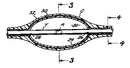
Referring to the drawings, particularly Figs. 1-6 thereof, a container system
for
pressurized fluids embodying the present invention includes a plurality of
assemblies of form-
retaining generally ellipsoidal chambers C and a tubular core T. Tubular core
T is coaxial to and
S sealingly secured to the chambers C. The tubular core T is formed along its
length with a
plurality of longitudinally equal distantly spaced apertures A which are in
fluid-transfer
communication with the interior 20 of each chamber C. The size of the
apertures A are pre-
selected so as to control the rate of evacuation of pressurized fluid from
chambers C. In this
manner, a very low fluid evacuation rate can be effected so as to avoid a
large and potentially
dangerous large burst of energy should one or more of the chambers C be
punctured.
Referring to Figs. 2 and 3, each chamber C includes a generally ellipsoidal
shell 24
molded of a suitable synthetic plastic material and having open front and rear
ends 26 and 28.
The diameters of the holes 26 and 28 are dimensioned so as to snugly receive
the outside
diameter of the tubular core T. The tubular core T is sonically welded to the
shells 24 so as to
form a fluid tight seal therebetween. The exterior of the shells 24 and the
increments of tubular
core T between such shells are pressure wrapped with suitable pressure
resistant reinforcing
filaments 30 to resist bursting of the shells and tubular core. A protective
synthetic plastic
coating 32 is applied to the exterior of the filament wrapped shells and
tubular core T.
More particularly, the shells 24 may be either roto molded, blow molded, or
injection
molded of a synthetic plastic material such as TEFLON or fluorinated ethylene
propylene.
Preferably, the tubular core T will be formed of the same material. The
pressure resistant
filaments 30 maybe made of a carbon fiber, Kevlon or Nylon. The protective
coating 32 may
be made of urethane to protect the chambers and tubular core against
abrasions, UV rays, or
thermal elements. The assembly of a plurality of generally ellipsoidal
chambers C and their
supporting tubular core T can be made in desired lengths such as 10 to 20
feet. The size of the
apertures A will depend upon various parameters, such as the volume and
viscosity of fluid being
contained, the anticipated pressure range, and the desired flow rate. In
general, smaller diameters
will be selected for gasses as composed to liquids. Thus, the aperture size
may generally vary
from about 0.010 to 0.125 inches.
CA 02334286 2000-11-29
WO 99/64345 PCT/US99/12705
Refernng to Fig. 5, the inlet or front end of the tubular core T is provided
with a suitable
conventional threaded male fitting 34. The discharge or rear end of a tubular
core T is provided
with a conventional threaded female fitting 36. Such male and female fittings
provide a pressure-
s type connection between contiguous lengths of tubular cores T.
5 Referring now to Figs. 7-11, there is shown a preferred fornl of apparatus
which may be
employed to carry out the method of the present invention for making the
assembly of generally
ellipsoid chambers C and tubular core T shown in Figs. 1-6. Referring to Fig
7, such apparatus
includes a frame F upon which are mounted in aligned relationship, commencing
with the right-
hand end of Fig. 7, a chamber shell loader L, a sonic welder S disposed to the
left thereof, a
filament winder W, disposed to the left of the sonic welder S and a plastic
coater P disposed to
the left of the filament winder F. The chamber shell loader L is shown in
greater detail in Fig.
8. Referring thereto such loader includes posts 38 and 39 having their lower
ends affixed to the
base 40 of frame F and with their upper ends supporting supply bin 4I below
which is disposed
a shell transfer tray 42. The transfer tray 42 is vertically movably supported
on the posts by
rollers 43 for movement between a first, raised loading position below the
loader shown in Fig.
7 and Fig. 8 in solid outline and a second, lower unloading position shown in
dotted outline in
Fig. 8. The upper portion of post 39 supports a spool 44 which carries a
coiled supply of tubular
core material T. The tubular core material is moved through the transfer tray
42 by
conventional power-operated pusher roller units 46 and 47 arranged on right-
hand post 39 and
a conventional power-operated pulley roller unit 48 arranged at the upper
portion left-hand post
38. A conventional power-operated hole puncher 50 is disposed above the pusher
roller unit
47. A first conventional power-operated rear tubular core cutter 52 is
positioned above the
pusher roller unit 46 and a like second front tubular core cutter 54 is
positioned above the pulley
roller unit 48. A conventional electrically operated counter and control box
56 is earned by left-
hand post 38 adjacent pulley roller unit 48. A conventional hydraulically-
operated pusher ram
unit 58 is carried by post 39 in horizontal alignment with the unloading
position of shell transfer
tray 42.
In the operation of the shell loader L a plurality of horizontally and
vertically aligned
arrays AA of the shells 24 are supported within the bin 41 of shell transfer
tray 42 at horizontally
equidistant positions, as shown in dotted outline in Fig. 8. The horizontally
aligned arrays of
shells 24 subsequently fall out of bin 41 in single horizontal rows into the
upper open end of
CA 02334286 2000-11-29
WO 99/64345 PCT/US99/12705
~6
transfer tray 42 and are temporarily held by suitable conventional means (not
shown) in coaxial,
horizontal alignment to receive a first increment of tubular core material T
from the supply roll
44 while the transfer tray is disposed in its raised shell loading position. A
first length of tubular
core material T is sequentially urged horizontally through the transfer tray
42 so as to be inserted
within the open ends of the shells 24 with a retention fit. During such
movement of the tubular
'core material through the shells, the hole puncher 50 will sequentially form
the apertures A at
longitudinally equidistant locations on the tubular core corresponding to
approximately the center
of the individual shells 24. With the tubular core material snugly received
within the open ends
of shells 24 the rear cutter 52 will sever the portion of tubular core
disposed adjacent the entrance
end of tray 42, while the front cutter 54 will sever the portion of the
tubular core adj acent the exit
end of the tray 42. The tray 42 and the assembly 55 of tubular core T-1 and
shells 24 contained
therewithin is then lowered to the dotted outline shell ej ection position
ofFig. 8, with the tubular
core in coaxial alignment with the plunger 59 of the hydraulic ram. The
hydraulic ram plunger
59 will then force the first shell and tubular core assembly 60 out of the
tray towards and into
the sonic welder S. The tray 42 will then be returned upwardly to its original
solid outline
position of Fig. 8 to receive the next array AA of chamber shells 24 and
tubular core material
T. It should be understood that suitable conventional power-actuated control
means are
incorporated in the chamber shell loader L to effect the above-described
operation of the parts
thereof.
As the first shell and tubular core assembly 60 is urged out of the tray 42 by
hydraulic
ram plunger 59, the left-hand or front end of the tubular core of such first
assembly 60 will abut
the right-hand or rear end of the shell and tubing core assembly 64 to force
such assembly into
sonic welder S in Fig. 9. The conventional sonic welder S includes fusion
horns 66 and 68
which serve to effect fusion of the tubular core T to the generally
ellipsoidal shaped shells 24.
Movement of the shell and tubular core assembly 64 into the sonic welder S by
plunger 59 will
cause the left-hand or front end of the tubular core of such assembly to force
the adjacent shell
and tubular core assembly 70 into the conventional filament winder W. As shown
in Fig. 10,
the conventional filament winder W includes a rotatable spool 72 which effects
high-speed
wrapping of reinforcement filaments 74 over the exterior surfaces of the
shells 24 and tubular
core T. It should be noted that the use of generally ellipsoidal shells 24
permits even coverage
of the filaments over the entire surface area of the shells and the tubular
core C between the shell.
CA 02334286 2000-11-29
WO 99/64345 PCT/US99/12705
7
Maximum bursting resistance is thereby achieved. At the completion of the
filament winding
step, the assembly of shells 24 and tubular core T are pushed to the left out
of the filament winder
W into the confines of the conventional plastic coater P. As indicated in Fig.
11, the plastic
~.
coater P is provided with a tank 80 containing a suitable synthetic plastic
such as TEFLON or
fluorinated ethylene propylene. The tank 80 is connected to a spray nozzle
member 82, which
as indicated in Fig. 11, serves to coat the exterior surfaces of the filament-
wound sTiells and
tubular core assembly 76 with a protective coating. The completed shell and
tubular core
assembly 84 is then urged out of plastic coater P by the shell and tubular
core assembly 76 during
the next stroke of hydraulic ram plunger 59.
Referring now to Figs. 12-15, there is shown an exemplar of a container system
for
pressurized fluids embodying the present invention. In these figures, such
container system take
the form of a pressurized gas pack having a housing H provided with an inlet
fitting 87 and a
discharge fitting 88. The discharge fitting 88 is connected to a conventional
mask 89. More
particularly, the housing H may be fabricated of a suitable non-flammable
material such as a
carbon fiber, polyethylene, synthetic plastic foam or cast into a dense block
of synthetic foam
rubber. Housing H is formed at its upper portion with a carrying handle 90.
Conventional inlet
fitting 87 is attached to one side of housing H in communication with the
upper end of a tubular
core element 91 of a first row 92 of vertically disposed generally ellipsoidal
chambers and
tubular core assemblies made in accordance with the aforedescribed method. The
lower end of
the tubular core element 91 is formed with a reverse curve section 93 and then
extends upwardly
through a second row 94 of generally ellipsoidal chamber and tubular core
assemblies. The
upper end of the tubular care element of the second row 94 is in turn formed
with a reverse curve
and extends downwardly through a third row 96 of generally ellipsoidal
chambers. Additional
assemblies are similarly arranged within the housing H. The upper end of the
tubular core of
the last row of assemblies is in communication with the conventional discharge
fitting 88,
attached to the left-hand side of the housing. Such discharge fitting 88 is in
turn fitted to a
flexible hose 97 connected to mask 89. The aforedescribed pack can be made
lighter and more
compact than conventional packs of this nature, and can serve as a regulatory
device containing
air, oxygen, nitrogen or other gasses.
From the foregoing description it will be understood that the container system
for
pressurized fluids embodying the present invention provides important
advantages over existing
CA 02334286 2000-11-29 '
WO 99/64345 PCT/US99/12705
fluid container systems. By way of example, should one or more of the chambers
C be ruptured,
only the pressurized fluid disposed within such chambers would undergo a
sudden release. The ,
pressurized fluid disposed in the other chambers could only escape into the
atmosphere at a safe
controlled rate because of the throttling effect of the apertures A. :j
While a particular form of the invention has been illustrated and described,
it will also
be apparent to those skilled in the art that various modifications can be made
without departing
from the spirit and scope of the invention. Accordingly, it is not intended
that the invention be
limited except by the appended claims.