Note: Descriptions are shown in the official language in which they were submitted.
L7.Jnil.Ge~r~y m .r~ ..
. CA 02334340 2001-02-02
Voith Paper Patent GmbH File No.: PN11052
Sankt Piolt~ne~r Strasse 43 "Fibron Air Table"
D-89522 Heidenheim
TRANSFER OF A LEAD STRIP OF A PAPER WEB
FIELD OF INVENTION
This invention relates to a method for transferring a lead strip of a paper
web from a
first travelling surface (e.g. of a press roll or of a press belt) of a paper
making
machine to a following section (e.g. further wet press or drying section) of
that
machine. In particular, the beginning of a still wet lead strip (or "tail") is
transferred
according to the invention. This is to facilitate the threading of the paper
web into the
machine. The present invention also relates to an apparatus for carrying out
said
method.
DESCRIPTION OF PRIOR ART
The present invention may preferably be used in a dewatering press section of
a
papermaking machine as disclosed in Fig. 1 of US patent 5,404,811. Therein a
still
wet paper web 9 is travelling from a wire belt 8 of a forming section through
three
press nips 16/17, 1/2 and ZI3 and thereafter via a paper roll 59 to a further
dewatering
press 60; then the still wet web is transferred to a drying section (not
shown). When
the machine is started up or after a web break, the web is threaded into the
machine
in a known manner;
Initially the web (having the full web width) is running behind the third
press nip
downwardly and is guided by a doctor 14 into a broke pulper (not shown,
positioned
below the machine). The web comprises a small edge strip, namely the so-called
lead
strip or "tail", severed from the web by a water jet positioned in the forming
section.
This tail is now transferred across paper roll 59 and via a bottom press felt
through
press 60 as well as through the following drying section. Then the width of
the tail is
increased up to the full width of the web.
N:wV~NpATVDCCUMENTS1D12240.4oe~0a1-01-29
' CA 02334340 2001-02-02
-2-
During the threading operation the web is already running with the full
machine speed
which may be more than 1000 m/min, in modern high speed machines up to about
2000 m/min. Therefore, the transfer of the tail from press roll 2 to the press
felt of
press BO is a very difficult step of the threading operation. Sometimes, this
is done
manually by means of an air jet being directed onto the surtace of roll 2,
thusly
severing the tail and forming a new beginning of the tail guided across paper
roll 59 to
the further press 60.
A modem high speed paper making machine normally comprises an apparatus for
carrying out this difFicult step. One known apparatus of this type is
disclosed in Fig. 2
of US patent 5,635,030. Here again, a paper web 1 is travelling downwardly
across a
press roll 5 from a press nip toward a doctor 7. A blast nozzle 6 (or
"separating blow
pipe") is provided to peel off the tail from press roll 5 and to transfer the
tail to paper
roll 2. A further blast nozzle 3 is arranged between the two rolls 5 and 2,
which blast
nozzle creates an air stream, the velocity of which is greater than the
velocity of paper
roll 2. Due to the Coanda-Effect, the air stream adheres to the rotating shell
of paper
roll 2 and guides the tail up to a stationary guide plate 8 which deflects the
air stream
and the tail toward subsequent press unit 8.
It is believed that the method and the apparatus disclosed in US '030 have
some
disadvantages, Among others, two blast nozzles are needed, one being
positioned
between the press roll 5 and the paper roll 2. Also, there is a large distance
between
the paper roll 2 and the infeed area of the press felt 17 of the following
press 8. As a
result, the tail transfer to the following press may not always be successful
in a
reliable manner.
In another concept, only a short distance has been provided between the paper
roll
and the infeed area of the following press felt. In other words; A felt roll
guiding the
following press felt to the following press has been arranged relatively close
to the
paper roll (as shown in Fig. 1 of US '811). Also, an air cushion has been
created onto
said infeed area by means of a series of blast nozzles. However, this concept
too,
~:vuINPATDCCUMEN11101224o.dor2ool-0~~9
G7. JHIY. GI~J~iu yG ~ JG . ~ nG ~ . _., .~ , . ~_. ~..~~
CA 02334340 2001-02-02
-3-
does not always operate satisfiactorily. Also, a so-called pony roll has been
suggested
to be arranged on said infeed area insfead of an air cushion; however this is
mechanical complicated and therefore not desirable.
SUMMARY OF THE INVENTION
It is an object of the present invention to significantly improve the transfer
of a tail
from a first travelling surface to a following machine section by means of a
novel
method and by means of an improved apparatus which will operate more reliably
than
previous proposals,
In particular, it is an object of the invention to provide a method which may
be carried
out without a lot of an operator's skill, so that new people, too, would be
able to start
the threading operation without a lot of practice.
It is a further object of the invention to allow an easy start of the
threading operation
by a reliable transfer of the tail, even with different paper grades (e~g.
different basis
weight) and with different machine speed including extremely high speed (e.g.
more
than 2000 m/min).
The aforementioned object as well as further objects that will come out later
are
attained by the features defined in the appended claims.
According to the method of the present invention (claim 1), a lead strip or
"tail" of a
paper web is transferred from a first travelling surface of an element of a
papermaking
machine to an infeed area of a second travelling surFace which guides the tail
into a
following machine section,
Preferably, said first travelling surface is the surface of a rotatable shell
of a press roll
which directly contacts the still wet paper web and which is part of a web
dewatering
KwnNParDOGUM&nrfvta122ao.aoaoo~-o~,7a
G'7. J H~'I. Gt'1YJ1 1G ~ JJ ~~ r ~ nG i . ~_ .. . .
CA~02334340 2001-02-02
-4-
press. It may also be the surface of a press belt travelling through a press
nip of a
web dewatering press.
Preferably, said second travelling surface is the web carrying surface of a
dewatering
press felt which guides the web through a subsequent dewatering press.
However,
said second travelling surface may also be the surface of a subsequent press
roll or
of a subsequent press belt. In another embodiment of the invention, the second
travelling surface is the surface of a dryer fabric which guides the web
through a part
of a dryer section following the press section of the papermaklng machine.
The method of the present invention comprises providing at least one air jet
for
peeling off of the flail from the first travelling surface and for
transferring it across a
rotating paper roll to the infeed area of the second travelling surface. More
particularly, the air jet initially reveres the tail running with the first
travelling surface,
thereby fotming a new beginning of the tail which is now transferred to the
second
travelling surface.
The most important step of the method of the present invention is to provide -
on the
infeed area of the second travelling surtace - an air cushion, this being
created by an
air table having a plurality of tiny orifices delivering air from an air
plenum to the air
cushion. According to the invention, the air cushion is created by a large
number of
tiny orifices which connect said air plenum to the air cushion and which are
distributed
substantially equally on said air table. This results in a significant
advantage, namely
that the oncoming tail (including its new beginning) is forced to lay on the
second
travelling surface with only a small amount of air moving with the second
travelling
surface. Therefore, the tail which is running at the high machine speed
together with
the second travelling surface, is reliably pressed onto the second travelling
surface. In
other words: According to the invention, it is avoided that the air bounces
off the
second travelling surface and that the tail is lifted with the air. Such an
undesirable
behavior would result from creating an air cushion by means of a series of
blast
nozzles which deliver too much air at a too high pressure.
N:WHNPATDDCUMCNT1012240.CcCZOCI-01~ZB
L 7 . .W 1 . Geuc.. ~ y ~ ~ .:.~ . ~ . , ._ . . _. _. . _ _ _ _
CA 02334340 2001-02-02
-5-
Also, it is avoided that too much air is directed into the following machine
section, e.g,
into a further dewatering press. Therein the press nip (or a similar wedge-
like gap)
would cause the air to filow sideways and to take the tail with it. This could
happen
both before the beginning of the tail has arrived the press nip and after
that.
In summary, the method of the invention results in a very easy and reliable
transfer of
the tail so that the transfer does not need much operator skill, Also, the
transfer will
work well with different paper grades and with difFerent machine speeds
including
high speed of modern paper machines.
The method of the invention may be further improved by the features defined in
the
daims depending from claim 1.
The present invention also includes an apparatus as claimed in claim 5 for
transferring the tail as described above, the apparatus comprising a peeling
jet device
for providing the at least one air jet as mentioned above; said peeling jet
device being
arranged close to the first travelling surtace (e.g. the surface of a press
roll).
Said apparatus further comprises a conventional paper roll which guides the
web
between the first and second travelling surfaces. The most important element
of the
apparatus of the invention is a so-called air table having a large number of
tiny holes
which connect an air plenum with the infeed area of the second travelling
surtace,
thereby creating an air cushion which is almost stationary on the second
travelling
surface. This results in the advantages described above.
Further improvements of the apparatus may be provided according to the claims
depending from claim 5.
BRIEF DESCRIPTION OF THE DRAIII~ING
N-\WINPA'npOCUMEN111012?A0.4a~1~01~29
' CA 02334340 2001-02-02
-6-
The attached drawing illustrates the invention by way of example.
Fig. 1 iS a schematic side view of two dewatering presses of a papermaking
machine including an air table.
Fig, 2 is a view along arrow II of Fig. 1.
Fig. 3 is a sideview of a segmented air table.
DESCRIPTION OF THE EMBODIMENTS SHOWN IN THE DRAWING
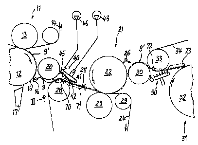
In Fig. 1, the normal path of a paper web to be dewatered in two presses 11
and 21 is
shown as a broken line and designated 9'. Web 9' is travelling through the nip
of a
top-felted press 11 comprising a bottom press roll 12 (which directly contacts
the web)
and a top press roll 13 positioned in the loop of an endless dewatering felt
14. Bottom
press roll 12 comprises a (downwardly) "first travelling surface" 15. Close to
it, a
peeling jet device 16 and a conventional doctor 17 are arranged.
A subsequent dewatering press 21 is bottom felted, It comprises a top press
roll 22
(which directly contacts the web) and a bottom felt 24 guided by felt rolls 28
and 29,
one (28) of which is positioned near the bottom press roll 12 of press 11. The
part of
felt 24 travelling from felt roll 28 to the nip of press 21 forms a so-called
"second
travelling surface" 25 comprising a so-called "infeed area" (positioned on
felt roll 28)
wherein the web comes into contact with felt 24. Web 9' is guided by a paper
roll 20
from the first (15) to the second (25) travelling surFace. There is a short
distance
between surface 15 and roll 20 as wel( as between roll 20 and surface 25.
Behind press 21, web 9' is travelling across a further paper roll 30 to a
dryer fabric 34
running across a fabric roll 33 transferring the web to a first drying
cylinder 32 of a
drying section 31.
Normally, at least one further press nip (not shown) may be arranged upstream
of
N;~WINPATDOCUMENT101224oAoa2001-01.QA
L~.~ni7.G:.uc.y w ~ . _ ..__. ~ .._ __
CA 02334340 2001-02-02
press 11. Typically, press 11 forms a third press nip of a complete press
section; then
press 21 forms a fourth press nip.
Before the web 9' is travelling along its normal path it runs across press
roll 12 and
doctor 17 downwardly into a brake pulper (not shown). For threading the web
into the
bottom felted press 21 (and further to dryer section 31 ) an edge strip or
"tail 9" of the
web is severed by peeling jet device 16, peeled off from the fiirst travelling
surface 15
and transfer-ed to the second travelling surface 25. An air table 40 extends
along the
infeed area of the second travelling surface 25 of felt 24. The air table also
extends
from paper roll 20 across the gap between paper roll 20 and felt 24 at felt
roll 28. The
width of air table 40 is slightly larger than the width of the tail 9 (see
Fig. 2).
The air table 40 comprises a box 41 connected to an air pressure source 43
providing
a relatively low air pressure, the box 41 thusly forming a so~called air
plenum, wherein
the air pressure is preferably between 5 and 20 psi.
Box 41 comprises a convex wall 42 facing to felt 24, the convex wall having a
plurality
of tiny holes 44 or orifices. The diameter of each hole may be about 0,5 to 2
mm; the
percentage of open area will be about 0,03 % to 0,1 %. Thereby a stable air
cushion
is created between air table 40 and the travelling surface 25 of felt 24
pressing the tail
onto felt 24 without moving much air toward the nip of press 21. As a further
improvement, box 41 is arranged in such a way, that the air cushion formed
between
box 41 and surface 25 is converging with respect to the web travel direction.
Close to
paper roll 20, an air jet pipe 45 is mechanically connected to box 41, the
pipe 45
being connected to a high pressure source 46. Peeling jet device 16, too, may
be
connected (not shown) to high pressure source 46.
Air jet pipe 45 may provide an air jet approximately tangential to the shell
of paper roll
20 contrary to the travel direction of the shell. At most one further air jet
or air curtain
may be directed from pipe 45 or from an additional pipe 67 (Fig. 3) toward the
infeed
area, i.e. toward felt roll 28. Peeling jet device 16 produces an air jet
about
N;1WINPA'11DOCUMENT101?240,40~1~0~.29
G7.Jhtll.GeJeJ~ i'~-m-. " n~., .~. ~...__ .._
CA 02334340 2001-02-02
- 8 .
perpendicular to the first travelling surface 15. If needed, jet device 16 may
additionally create an air jet toward paper roll 20.
In order to further improve the reliable transfer of the tail to the second
travelling
surtace 25 or 34 it may be helpful to provide suction means (70 - 73) in the
area of the
tail within roll 28 and/or within roll 33 andlor beneath felt 24 andlor fabric
34.
Fig. 2 shows the peeling jet device 16 and the air table 40 in their operating
position
held during a threading operation. During the normal operation of the
papermaking
machine, the peeling jet device 16 is removed to the outside of the machine.
For this
purpose, a pneumatic cylinder (not shown) or a similar equipment is provided
which
moves the device 16 automatically into or out of its operating position, as
indicated by
a double arrow. If needed, the air table 40 may also be connected to a
pneumatic
cylinder.
In order to facilitate the transfer of tail 9 from press roll 22 via paper
roll 30 to the
drying fabric 34, a further peeling jet device 26 is arranged close to the
surface of
press roll 22, Also, a further air table 50 may be arranged below fabric roll
30. In this
case, press roll 22 forms the said first travelling surtace and the drying
fabric 34 forms
the said second travelling surface.
Fig. 3 shows a further developed air table 60. It is divided into various
(e.g. three)
segments 61 to B3. Each segment is formed as a box similar to box 41 of Figs.
1 and
2. One (61) of the boxes is mechanically connected to a supporting device 65
which
supports the complete air table 60 and which may be connected (if needed) to a
pneumatic cylinder (not shown) of the type explained above. The segments 61
and 62
as well as the segmenfis 62 and 63 are mechanically connected one to the other
by a
pivot 64. Also, the outer end of the third segment 63 is connected to support
65 by a
spindle 66 (or threaded bolt). Therefore, the distance between the outer end
of
segment 63 and support 65 may be changed. In other words: The average radius R
of
the curvature of the complete air table 60 may be changed. This allows to
change the
N~1MNPAIIpOCtJMENT10122~40,Cod001-01.29
G7.J1-Iio.GeJcm w .~.. ., , W .,.~ ...,..
y CA 02334340 2001-02-02
.. 9 _
form of the complete air table 60 in order to adapt the same to various
operating
conditions, e.g. to various paper grades or to various machine speeds. As an
example: The form of the complete air table may be approximately flat. The
segments
61-63 may be provided with equal air pressure or with different air pressures.
Finally,
it is possible to create air tables of different size by using a different
number of
segments (e.g. two or three or four etc,).
N;\WINPAT'~OCtIMENr101'~0,doa2C01~01.28