Note: Descriptions are shown in the official language in which they were submitted.
CA 02334654 2000-12-07
WO 99/66740 PCT/US99/12897
LOCATION UPDATE METHOD AND
INTER CORE NETWORK ENTITY HANDOVER METHOD
BACKGROUND OF THE INVENTION
1. Field of the Invention.
This invention relates in general to a cellular communication system, and
more particularly to a location update method and an inter Core Network (CN)
entity
handover method, and further more particularly to a location update method and
an
inter-SGSN handover method in a 3`d Generation (3G) cellular system.
2. Description of Related Art.
Cellular systems have had a direct effect on the lives of millions over the
past
few years. For the first time, people are able to make and receive phone calls
without being tied to a specific location. Mobile phones, as part of the
cellular
systems, have allowed people to break the tie between location and access to
communication. Mobile phones have also allowed people to reach another who is
in
move. With the development in cellular systems, people are allowed to reach
another who is mobile in anywhere at anytime.
The first generation of mobile communication systems were born in the early
1980s. The marriage of radio and telephone technologies gave birth to mobile
phones and triggered a turning point in telecommunications. Adding radio
access to
a telephone network meant that for the first time in history, the concept of a
telephone being at a fixed point in the network was no longer valid. The
benefits of
being able to make and receive telephone calls anywhere had appeal to business
people - the original market. In the first generation of cellular networks,
analog
wireless technology were used for the user connection (called the "air
interface").
Every voice channel had its own narrow frequency band, using a technology
called
Frequency Division Multiple Access (FDMA).
However, as the demand for mobile phones grew and grew, regularly
exceeding forecasts, it became obvious that the available radio spectrum would
not
be adequate to accommodate the expected numbers of mobile phone users. The
digital technology became the solution to the problem. The answer lay in new
1
CA 02334654 2000-12-07
WO 99/66740 PCT/US99/12897
digital wireless technologies that allow larger numbers of mobile subscribers
to be
supported within a given frequency allocation. Time Division Multiple Access
(TDMA) technology is used in which a broader frequency channel is divided into
intermittent time-slots, i.e. several calls share the same frequency channel
at any one
time. The digital technology also offered other important benefits. It
provided
better voice quality and improved security against unauthorized eavesdropping.
Another technology, Code Division Multiple Access (CDMA) has also been
developed subsequently to increase capacity.
The first and second generation mobile communication systems were mainly
set to support voice communications, although today's mobile phones can also
be
used for data transfer at rates that are acceptable for relatively low-speed
data
applications such as sending and receiving of faxes and e-mail. However, these
systems do not support high-speed data or video applications. The third
generation
mobile communication system is being developed to remove the bandwidth
bottleneck and support a whole new range of voice, data, video, and multimedia
services. For example, smart messaging is bringing Internet services to every
mobile user's fingertips. As people become used to the freedom that mobile
communications have provided, they will become more demanding about the
information and services required to benefit their lives.
The demand by consumers all over the world for mobile communications
service continues to expand at a rapid pace and will continue to do so for at
least the
next decade. To satisfy such demand, more and more innovative mobile
telecommunications networks are being built in this growing industry.
In the 3`' generation cellular systems, many practical techniques are being
developed over the past few years. The mobile telecommunication network
comprises switching functions, service logic functions, database functions,
and
Mobility Management (MM) functions that enable subscribers to be mobile. These
are some of the functions provided by Mobile Switching Centers (MSCs) for
serving
Circuit Switched (CS) connections, by Visitor Location Registers (VLR) for
serving
CS connections, or by other network entities, for example, Serving GPRS
Support
Node (SGSN) for Packet Switched (PS) connections (GPRS refers to General
Packet
Radio System).
2
CA 02334654 2000-12-07
WO 99/66740 PCT/US99/12897
Generally, the database in the Core Network (CN) keeps tracks of the
location of Mobile Stations (MSs). In one case, the CN comprises both
entities,
MSC and SGSN, to implement such database. Each of the MSs can have a CS or PS
connection service from the CN by sending radio signals to its Base Station
(BS).
Each of the BSs is controlled by a Radio Network Controller (RNC) which
connects
to the CN.
When a MS with an active connection moves from one area to another, a
handover (also known as handoff) procedure is performed between the BSs During
a handover procedure, a CN entity can operate in two different ways: one is
called
anchoring, and the other is called floating. In an anchoring procedure, the
control of
the MS remains in the first network entity where the connection between the MS
and
the CN was started, whereas in a floating procedure, the control of the MS is
changed along with the move of the MS. Fig. 6 shows an anchoring procedure.
Fig.
7 shows a floating procedure.
One of the problems in developing a 3`d generation cellular system is location
update when a MS, e.g. with an active connection, moves from one area to
another.
This problem does not appear in a 2"d generation cellular system due to the
fact that
the 2od generation cellular system does not use macro diversity and Iur-
interface in
the systems. In a conventional 2"d generation cellular system, e.g. GSM
(Global
System for Mobile communications), only one Base Station (BS) receives radio
signals from a MS. Accordingly, when a MS moves from one area to another, the
MS knows which BS controls the MS so that a location update can be performed
by
communicating between the MS and the CN via this BS. However, in a 3d
generation cellular system, to increase the capacity of the data transmission,
a macro
diversity and Iur-interface concept are introduced in the system. In
particular,
multiple Base Stations can receive radio signals from and to a MS, and due to
the
Iur-interface, the BSs are not necessarily connected to one Radio Network
Controller
(RNC). A Serving RNC (SRNC) informs the BS which MS is under its control and
is connected to the CN entities in the CN. When a MS moves, the control to the
MS
may be changed from one RNC to the other RNC in a fashion that the MS may not
be involved. As a result, when a MS moves from one area to another, the MS
does
3
KC V . VON: E V A -hiUHNCHLN 04 :26- 9- 0, "` - 65 . 612 912 0574-~ +49 89
23994.465. # 8
CA 02334654 2000-12-07
US 009912897 .
26-09-2000
not know when the SRNC is changed If the MS sends a location update before the
SRNC is changed, the location update maybe sent to a wrong CN -entity..
Another problem in a 3 generation _celIur systems is: that dieing an active
PS connection from it SGSN, a MS may move to an area where the SGSN should be
s -changed. For instance, when a SRNC for e.MS is changed, the new. SRNC is.
connected to the new SGSN. In a 3e gtsiectation cellular systetti, changing of
a
controlling SGSN needs to be executed i'166 CN because the MS does: not know
when it has entered in the new SGSN area'and which RNC-cotttrols. the MS duo
to
the possible macro diversity and Iur-interface.. In the existing' 2 ¾
generation cellular
io system,*the new SGSN has to request from the old SGSN all information after-
the
new SGSN receives a location update from'.the MS. During such a SGSN handover.
all the radio related entities in RNCs, BSs,-MSS, etc., have
to'be'=releascd:.. bus,=it is
Inefficient to perform an inter-SGSN' haudover.
Forexample, WO-A-95 28063 teaches' a me cad of location management in
15 e:g. a GPRS system. According to WO-A-95 28063, the' mobile
=statioa.tuggetl the
transmission of location management messages from the Mobile. Station to the
network on the basis of information broa&ast by the base :stations And
infoimiition
on the current. mobility management stale of the connection. However, the
network
needs to trigger the location managemelit=message to be sent to the mobility '
20 management entity of the network.
Therefore, it can be seen that there is a need for an initiation scheme for
location update -of a MS in a 3` generation cellular system. It can also be
seeen.tkat:
there is a need for an inter-SGSN handover'scheme in a 3'd generation
cellular. ,
system.
25 S 5CAARY PP. THE INY rON':
Tv' overcome the problems in the prior art described above, and to overcome
other problems that will become apparent upon reading and uncle standing. the
present specification, the present invention :discloses a scheme for providing
a
notification to a Mobile Station (MS) to tiate a location update in, a Pgene
ration
30 system. Further, the present invention discloses a scheme for providing
update of
location of the MS to a new Core Network '(CN) entity via interface between
the.CN
entities, Furthermore, the present invention discloses a scheme for providing
update
of location of the MS to a new CN entity via'interface between.a CST entity
and-a=
Seining RNC (SRNC).
4.
AMENDED SHEET
a. v . V VIV : L'Yli-117UL'IVLI-1L=:V U4 : 2 3 - 4- 0 CA 02334654 2000-12-07
E, 12 91 2 0574. +49 89 2639944.65 : o 9
... uy. .,._ .&_tr~
26-09-2000.
US 009912897
Moreover, the present invention discloses a scheme for providing' an inter
Core:
Network (CN) handover, e.g. inter-$09N handovcr, in a 3"d giicration cellular
system.
In the present invention, several schemes'for, notifying theMS.to initiate a
location =
update f om the MS to a Core Network R(CN) while the MS is having an ongoing
connection arc disclosed. In one emboc nnent, the present invention .
4A'
AMENDED SHEET
CA 02334654 2000-12-07
WO 99/66740 PCT/US99/12897
provides a notification to the MS when there is a Serving Radio Network
Controller
(SRNC) relocation, which includes the following steps of: serving the MS by a
first
RNC; moving the MS from a first area to a second area wherein service in the
first area
is controlled by the first RNC, and service in the second area is controlled
by a second
RNC; serving the MS by the second RNC, so that the control of the MS is
changed
from the first RNC to the second RNC; determining by the second RNC whether a
notification to the MS for the location update is needed based on factors such
as
configuration of the CN which is connected to the plurality of RNCs and/or the
types
of connection that the MS is having, etc.; and notifying, by the second RNC,
the MS
that a location update from the MS should be performed; and if the
notification to the
MS for the location update is determined by the second RNC to be needed,
updating a
location of the MS in the CN. Alternatively, the RNC does not determine
whether a
notification to the MS for the location update is needed. It is up to the MS
to
determine whether the location update should be made. In this case, the second
RNC
directly notifies the MS that a location update from the MS should be
performed, and
if the MS decides to update the location, MS sends the location update to the
CN.
In an alternative embodiment, the present invention provides an update of the
location of the MS from a SRNC to a new idle CN entity via an interface
between
the SRNC and the new idle CN entity when there is a Serving Network Controller
(SRNC) relocation, which includes the following steps of. serving the MS by a
first
RNC; moving the MS from a first area to a second area wherein service in the
first area
is controlled by the first RNC, and service in the second area is controlled
by a second
RNC; serving the MS by the second RNC, so that the control of the MS is
changed
from the first RNC to the second RNC; determining by the second RNC whether
the
location update is needed based on factors such as configuration of the CN
which is
connected to the plurality of RNCs and/or the types of connection that the MS
is
having, etc.; and sending update of the location of the MS by the second RNC
to a new
idle CN entity (an idle CN entity is a CN entity which does not have an active
connection for that particular MS) via an interface between the SRNC and the
new CN
entity. The CN entity can be a MSC/VLR (Mobile Switching Center/Visitor
Location
Register) or a SGSN (Serving GPRS Support Node, GPRS is General Packet Radio
System). Alternatively, the CN entity determines whether the location update
is
5
CA 02334654 2000-12-07
WO 99/66740 PCT/US99/12897
needed. If the location update is needed, the RNC then sends the location
update to the
new CN entity via the interface between the SRNC and the new CN entity.
In an additional embodiment of the present invention, a notification to the
MS can also be triggered by the CN entity (for example MSCNLR or SGSN, etc.),
i.e. the CN entity initiates ordering of a location update procedure from MS.
This
scheme includes the following steps of. serving the MS by a first RNC; moving
the
MS from a first area to a second area wherein service in the first area is
controlled by
the first RNC, and service in the second area is controlled by a second RNC;
serving
the MS by the second RNC, the plurality of RNCs being connected to the CN, so
that
the control of the MS is changed from the first RNC to the second RNC;
determining
by the CN entity whether the location update is needed base on factors such as
configuration of the CN and/or the types of connection that the MS is having,
etc.;
notifying, by the CN entity, the MS that a location update from the MS should
be
performed; and updating a location of the MS in the CN. Alternatively, after
receiving
a notification from the CN entity, it is up to the MS to decide whether the
location
update should be performed.
In an additional alternative embodiment of the present invention, an update of
the location of the MS from an active connection CN entity to a new idle CN
entity
via an interface between the active connection CN entity and the new idle CN
entity
when there is a Serving Radio Network Controller (SRNC) relocation. The scheme
includes the following steps of. serving the MS by a first RNC; moving the MS
from a
first area to a second area wherein service in the first area is controlled by
the first
RNC, and service in the second area is controlled by a second RNC; serving the
MS
by the second RNC, the plurality of RNCs being connected to the CN, so that
the
control of the MS is changed from the first RNC to the second RNC; determining
by
the active connection CN entity whether the location update is needed based on
factors
such as configuration of the CN which is connected to the plurality of RNCs
and/or the
types of connection that the MS is having, etc.; and sending update of the
location of
the MS by the active connection CN entity to the new idle CN entity via an
interface
between the active connection CN entity and the new idle CN entity. The CN
entity
can be a MSCNLR (Mobile Switching CenterNisitor Location Register) or a SGSN
(Serving GPRS Support Node, GPRS is General Packet Radio System).
Alternatively,
6
CA 02334654 2000-12-07
WO 99/66740 PCT/US99/12897
the new idle CN entity determines whether the location update is needed. If
the
location update is needed, the active connection CN entity then sends the
location
update to the new idle CN entity via the interface between the active
connection CN
entity and the new idle CN entity.
In a further additional alternative embodiment of the present invention, a
SRNC only moves Radio Resource (RR) control into a new RNC (i.e. a second
RNC),
and an old CN entity (i.e. the active CN entity before changing the RNC)
remains
control in the Core Network (CN), i.e. the old CN entity is still active after
changing
the RNC. The control in the CN is changed along with the location update from
the
MS. Accordingly, without updating from the MS, the old CN entity is active,
and the
control in the CN is anchored. In this case, the scheme for providing an
update to a
new CN entity includes the following steps: serving the MS by a first RNC;
moving
the MS from a first area to a second area, wherein service in the first area
is controlled
by the first RNC, and service in the second area controlled by a second RNC; a
plurality of RNCs being connected to the CN so that the control of the MS is
changed
to from the first RNC to the second RNC; notifying the MS on the RNC change;
and
sending update of the location of the MS by the MS into the new and old CN
entities.
In the above and many other embodiments, the Core Network entity can be a
Mobile Switching CenterNisitor Location Register (MSCNLR) which serves the
Circuit Switched (CS) connections, or a Serving GPRS Support Node (SGSN)
which serves the Packet Switched (PS) connections, or an Interworking
Unit/SGSN
(IWU/SGSN) which serves PS connections in 3G CN entity interworking with 2G
CN entity. 3G stands for the 3' generation cellular system, and 2G stands for
the 2"'
generation cellular system.
Further in one embodiment of the present invention, a CN entity receiving
location update of the MS may serve both an old RNC and a new RNC. In an
alternative embodiment, the old RNC and the new RNC are served by different CN
entities.
The present invention also provides a mobile telecommunication system. In
one embodiment, the system comprises: a Mobile Station (MS); and at least two
Radio Network Controllers (RNCs), at least one of the RNCs being arranged to
send a
7
CA 02334654 2000-12-07
WO 99/66740 PCT/US99/12897
notification to the MS in a response to a RNC relocation between the at least
two
RNCs.
In another embodiment of the present invention, the system comprises: a
Mobile Station (MS); at least two Radio Network Controllers (RNCs); and a Core
Network (CN), the CN including at least one CN entity, at least one of the
RNCs being
arranged to send location update of the MS to the one CN entity via an
interface
between at least one RNC and at least one CN entity in a response to a RNC
relocation
between the at least two RNCs.
In an additional embodiment of the present invention, the system comprises:
a Mobile Station (MS); at least two Radio Network Controllers (RNCs); and a
Core
Network (CN), the CN including at least one CN entity, the at least one CN
entity
being arranged to send a notification to the MS in a response to a RNC
relocation
between the at least two RNCs.
In a further embodiment of the present invention, the system comprises: a
Mobile Station (MS); at least two Radio Network Controllers (RNCs); and a Core
Network (CN), the CN including at least one CN entity, the at least one CN
entity
being arranged to send location update of the MS to a second CN entity via an
interface between two CN entities in a response to a RNC relocation between
the at
least two RNCs.
The present invention further provides schemes for providing an inter CN
entity handover, such as inter-SGSN handover, in a 3'd generation cellular
system,
whereby one of the SGSNs is a 2G SGSN or 3G SGSN, and the other one of the
SGSNs is a 2G SGSN or 3G SGSN. This is accomplished by firstly determining
whether both of the SGSNs are 2G SGSN or 3G SGSN or whether one is 2G SGSN
and the other is 3G SGSN, and secondly operating the corresponding inter-SGSN
handover.
One advantage of the present invention is that it allows the location update
of
the MS to be sent to a correct CN entity in a 3`d generation cellular system
where there
is a Serving RNC relocation.
Another advantage of the present invention is that it allows an inter CN
entity
handover, such as inter-SGSN handover, in a 3rd generation cellular system
whereby
the radio related entities in RNCs, BSs, and MSs, etc., are maintained during
the inter-
8
CA 02334654 2008-10-30
SGSN handover. The new SGSN receives all information from the old SGSN while
establishing the new SRNC during a RNC relocation.
According to a further broad aspect of the present invention, there is
provided a
method for providing a notification to a Mobile Station (MS) for a location
update of the MS
in a mobile telecommunication system wherein the MS is controllable by one of
a plurality
of Radio Network Controllers (RNCs), comprising the steps of a) serving the MS
by a first
RNC ; b) moving the MS from a first area to a second area wherein service in
the first area
is controlled by the first RNC, and service in the second area is controlled
by a second RNC;
c) serving the MS by the second RNC, so that control of the MS is changed from
the first
RNC to the second RNC; and d) notifying the MS that a location update from the
MS
should be performed.
According to a further broad aspect of the present invention, there is
provided a
mobile telecommunication system comprising a) a Mobile Station (MS); and b) at
least two
Radio Network Controllers (RNCs), wherein a notification is sent to the MS in
a response to
a RNC relocation between the at least two RNCs.
According to a further broad aspect of the present invention, there is
provided a
mobile telecommunication system comprising: a) a Mobile Station (MS) ; b) at
least two
Radio Network Controllers (RNCs); and c) a Core Network (CN), the CN including
at least
one CN entity, at least one of the RNCs being arranged to send location update
of the MS
to the one CN entity.
According to a further broad aspect of the present invention, there is
provided a
method of mobility management in a mobile telecommunication system including a
mobile
station (MS), a radio network having a plurality of radio network controllers
(RNCs)
controlling use of radio resources and including a serving RNC, and a
plurality of core
network entities (CNEs) each of which connects to at least one of the RNCs;
the MS having
at least one type of connection connected to the CNEs, the CNEs storing
information of a
current location of the MS and connecting at least a first type of connections
of the MS to a
second network and a second MS of the mobile telecommunication system, and a
radio
connection of the MS being controlled by the serving RNC, and the connection
of MS being
routed to/from a respective CNE via the serving RNC, the method comprising:
controlling
the mobile station (MS) (405) by a first RNC (406) of the plurality of RNCs,
the first RNC
9
CA 02334654 2008-10-30
being the serving RNC; moving control of the MS to a second RNC according to a
predefined criteria, service in a first area being controlled by the first
RNC, and service in a
second area being controlled by the second RNC when the MS is moved from the
first area
to the second area, the second RNC being the serving RNC; and updating
location of the MS
to the CNE connected to the second RNC.
According to a still further broad aspect of the present invention, there is
provided a radio access network for a mobile telecommunication system
comprising: a
mobile station (MS); a radio access network including a plurality of radio
network
controllers (RNCs) controlling use of radio resources; a plurality of core
network elements
(CNEs) each connected to at least one of the RNCs, the MS having at least one
controlling
CNE storing information on a current location of the MS and connecting at
least a first type
of connections of the MS to other networks and other mobile stations of the
mobile
telecommunication system, a radio connection of MS being controlled by a
serving RNC
and the connection of the MS being routed to/from a respective CNE via the
serving RNC,
the serving RNC functionality of the connection being moved from a first one
of the RNCs
to a second one of the RNCs in response to meeting a predefined criteria; and
wherein the
radio access network is arranged to update a location of the MS in response to
having moved
the control of the radio connection of the MS from the first RNC to the second
RNC .
Other embodiments to implement a method or procedure in accordance with the
present invention may include alternative or optional additional aspects.
These and various
other advantages and features of novelty which characterize the invention are
pointed out
with particularity in the claims annexed hereto and form a part hereof.
However, for a better
understanding of the invention, its advantages, and the objects obtained by
its use, reference
should be made to the drawings which form a further part hereof, and to
accompanying
descriptive matter, in which there are illustrated and described specific
examples of an
apparatus in accordance with the invention.
BRIEF DESCRIPTION OF THE DRAWINGS
Referring now to the drawings in which like reference numbers represent
corresponding parts throughout:
Fig. 1 illustrates a basic, generic mobile telecommunication system;
9a
CA 02334654 2008-10-30
Fig. 2 illustrates a basic, generic handover process where radio signals are
passed as
a vehicle or mobile unit moves from one area to another;
Fig. 3 illustrates a Serving RNC connected to CN entities in a 3`d generation
cellular
system in accordance with the present invention;
Fig. 4 illustrates an inter-SGSN handover in a mobile telecommunication system
in
accordance with the principles of the present invention;
Fig. 5 illustrates a block diagram of a change of control in a Core Network
(CN)
triggered by a change of Serving Radio Network Controller (SRNC) (i.e. RNC
relocation) in
a 3rd generation cellular system in accordance with the principles of the
present invention;
Fig. 6 illustrates an anchoring procedure when Mobile Station (MS) moves from
one
area to another;
Fig. 7 illustrates a floating procedure when Mobile Station (MS) moves from
one
area to another;
Fig. 8 illustrates a Mobile Station (MS) having at least one CS connection
connected
to a MSC/VLR before the MS moves into a second area in a 3d generation
cellular system in
accordance with the principles of the present invention;
9b
CA 02334654 2000-12-07
WO 99/66740 PCT/US99/12897
Fig. 9 illustrates a MS having at least one CS connection connected to a
MSGVLR after the MS moves into a second area in a 3`d generation cellular
system
in accordance with the principles of the present invention;
Fig. 10 illustrates a MS having at least one PS connection connected to a
SGSN before the MS moves into a second area in a 3' generation cellular system
in
accordance with the principles of the present invention;
Fig. 11 illustrates a MS having at least one PS connection connected to a
SGSN after the MS moves into a second area in a 3`d generation cellular system
in
accordance with the principles of the present invention;
Fig. 12 illustrates an inter-SGSN handover from a 3G SGSN to a 3G SGSN
in a 3rd generation cellular system in accordance with the principles of the
present
invention;
Fig. 13 illustrates an inter-SGSN handover from a 2G SGSN to a 2G SGSN
in a 3`d generation cellular system in accordance with the principles of the
present
invention;
Fig. 14 illustrates an inter-SGSN handover from a 3G SGSN to a 2G SGSN
in a 3`d generation cellular system in accordance with the principles of the
present
invention;
Fig. 15 illustrates an inter-SGSN handover from a 2G SGSN to a 3G SGSN
in a 3'd generation cellular system in accordance with the principles of the
present
invention;
Fig. 16 illustrates a separate implementation of a Core Network (CN);
Fig. 17 illustrates an integrated implementation of a Core Network (CN); and
Fig. 18 illustrates an alternative inter-SGSN handover from a 3G SGSN to a
3G SGSN in a 3'd generation cellular system in accordance with the principle
of the
present invention.
DETAILED DESCRIPTION OF THE INVENTION
In the following description of the exemplary embodiment, reference is made
to the accompanying drawings which form a part hereof, and in which is shown
by
way of illustration the specific embodiment in which the invention may be
practiced.
It is to be understood that other embodiments may be utilized as structural
changes
CA 02334654 2000-12-07
WO 99/66740 PCTIUS99/12897
may be made without departing from the principles or scope of the present
invention.
The present invention provides a notification to a Mobile Station (MS) to
initiate a location update in a 3' generation system. Further, the present
invention
provides update of location of the MS to a new Core Network (CN) entity via
interface between the CN entities. Furthermore, the present invention provides
update of location of the MS to a new CN entity via interface between a CN
entity
and a Serving RNC (SRNC). Moreover, the present invention provides an inter
Core Network (CN) handover, e.g. inter-SGSN handover, in a 3`d generation
cellular
system.
Fig. I illustrates a basic, generic mobile telecommunication system 100. The
system 100 can be connected by blocks. The voice fed to the microphone of a
handset 110 is transmitted through atmosphere media 112 to a Base Station (BS)
114. From the BS 114, a signal is routed to a network, such as Public Switched
Telephone Network (PSTN), or a Packet Data Network (PDN), via a switching
center 116 and or rebroadcast 118. Similarly, at the network end, voice
information
is transmitted from a BS 120 and received by a handset 122. Each handset 110,
112
and BS 114, 120 have a transmitter/receiver (transceiver) function commonly
known
to a person skilled in the art.
In a 3rd generation cellular network, multiple Base Stations (BSs) can receive
radio signals from a Mobile Station. Due to macro diversity and lur-interface,
the
BSs are not necessarily controlled by one Radio Network Controller (RNC). When
a Mobile Station (MS) moves from one area to another, radio signals may be
passed
from one area to another. This pass is often called handoff or handover. Fig.
2
illustrates a simple, basic handover process 200. As a vehicle 210, a MS,
moves
away from BS 212, its signal strength decreases. The BS 212 monitors the
signal
strength within the duration of the call. When the signal strength falls below
a
predetermined threshold level, the network 214 asks all predetermined
candidates
neighboring BS 220 to report the signal strength of the mobile in the vehicle
210. If
the signal strength in the neighboring cell 220 was stronger by a
predetermined
amount, the network 214 attempts to handover the call to the candidate
neighboring
11
CA 02334654 2000-12-07
WO 99/66740 PCTIUS99/12897
cell 220. These elements are integrated to form a part of a ubiquitous
coverage radio
system that can connect to Public Switched Telephone Network (PSTN) 240.
Fig. 3 illustrates a Serving RNC (SRNC) connected to CN entities, such as
MSCNLR or a SGSN, in a 3`d generation cellular system in accordance with the
present invention. The MSCNLR serves MS' requests for Circuit Switched (CS)
connections. Accordingly, the MSCNLR is generally communicated to a network
such as PSTN, etc.. The SGSN serves MS' requests for Packet Switched (PS)
connections. Accordingly, the SGSN is generally communicated to a network such
as Packet Data Network (PDN), e.g. Internet Protocol (IP), etc.
Fig. 4 illustrates an inter Core Network (CN) entity handover 400, for
example, inter-SGSN handover in a 3`d generation cellular system in accordance
with
the present invention. Inter-SGSN handover is a handover between two SGSN
network entities 402, 404 when a Mobile Station 405 moves from one area to
another. The details of the inter-SGSN handover will be explained later in
Figs. 12-
15. During an inter-SGSN handover, a SRNC may change from an old SRNC 406
to a new SRNC 408 as shown in Fig. 4. It is appreciated that since a SRNC can
be
connected to a number of SGSNs, sometimes there may not be a SRNC relocation.
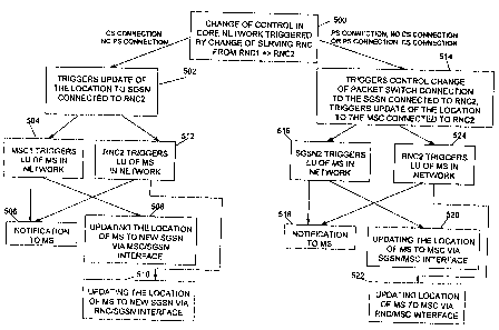
Fig. 5 illustrates a block diagram of a change of control and Mobile Station
related data in a Core Network (CN) triggered by a change of Serving Radio
Network Controller (SRNC) (i.e. RNC relocation) 500 in a 3'd generation
cellular
system in accordance with the principles of the present invention. There are
several
methods of initiating a location update of a MS. In one case, the MS has a
Circuit
Switched (CS) connection but not a Packet Switched (PS) connection. The change
of serving RNC from RNC 1 to RNC2 triggers update of the location of the MS to
an
idle (also called no connection) Core Network (CN) entity, such as SGSN,
connected to RNC2 in box 502. There are at least four types of
notification/updating
the location of the MS. The first one is that the CN entity MSC 1 (Mobile
Switching
Center) triggers location update in the network in box 504 by notifying the MS
by
sending the MS a message that location update should be performed, if
necessary, in
box 506. The second one is that the CN entity MSCI triggers location update in
the
network in box 504 by updating the location of the MS to a new idle network
entity,
such as SGSN, via MSC/SGSN interface in box 508. The third one is that the
RNC2
12
CA 02334654 2000-12-07
WO 99/66740 PCT/US99/12897
triggers location update of the MS in the network in box 512 by notifying the
MS by
sending the MS a message that location update should be performed, if
necessary, in
box 506. The fourth one is that the RNC2 triggers location update of the MS in
the
box 512 by updating the location of the MS to a new idle network entity, such
as
SGSN, via RNC/SGSN interface in box 510.
In a second case, the MS has a Packet Switched (PS) connection but not a
Circuit Switched (CS) connection. The change of serving RNC from RNC1 to
RNC2 triggers control change of the packet switch connection to the SGSN
connected to the RNC2 and also may trigger update of the location of the MS to
an
idle Core Network (CN) entity, such as MSC, connected to RNC2 in box 514.
There
are at least four types of notification/updating the location of the MS. The
first one
is that the CN entity SGSN 2 (Serving GPRS Support Node, GPRS is referred to
as
General Packet Radio System) triggers location update in the network in box
516 by
notifying the MS by sending the MS a message that location update should be
performed, if necessary, in box 518. The second one is that the CN entity SGSN
1
triggers location update in the network in box 516 by updating the location of
the
MS to a new idle network entity, such as MSC, via SGSN/MSC interface in box
520. The third one is that the RNC2 triggers location update of the MS in the
network in box 524 by notifying the MS by sending the MS a message that
location
update should be performed, if necessary, in box 518. The fourth one is that
the
RNC2 triggers location update of the MS in the box 524 by updating the
location of
the MS to a new idle network entity, such as MSC, via RNC/MSC interface in box
522.
In a third case, the MS has both a Packet Switched (PS) connection and a
Circuit Switched (CS) connection as shown in Fig. 5. The location update
notification and/or update procedures can be the same as in the second case
described above, see from box 514 to box 522, except that it may not trigger
update
of the location to an idle Core Network (CN) entity, such as MSC, connected to
RNC2 in box 514.
It is appreciated that whether the trigger function is performed may depend
on factors such as configuration of the CN and/or the types of connection that
the
MS is having, etc.
13
CA 02334654 2000-12-07
WO 99/66740 PCT/US99/12897
After changing control of the SRNC, the SRNC may determine whether a
location update is necessary. It is appreciated that after the MS receives a
notification, the MS may also decide whether a location update should be made.
The conditions for when the notification to the MS is needed may depend on the
CN
configuration and/or the types of connection that the MS is having, etc.. CN
may
have a single Mobility Management (MM) control plane or C-planes (known as an
integrated implementation as shown in Fig. 17) or a number of control planes
(known as a separated implementation as shown in Fig. 16). In the single C-
plane
CN, an anchoring operation can be performed when the SRNC is changed. In the
multiple C-planes CN, a floating operation can be performed when the SRNC is
changed. As a result, there is no need for notification to the MS in the CN
with an
integrated implementation.
Fig. 16 illustrates a separate implementation. In one embodiment, the CN
entities, e.g. MSC and SGSN, are not linked. In another embodiment, the CN
entities, e.g. MSC and SGSN, are linked.
Fig. 17 illustrates an integrated implementation. The CN entities, e.g. MSC
and SGSN, are integrated in the implementation.
The following table shows the conditions on which SRNC's determination is
based:
Target RNC "1" Target RNC "2"
Source RNC "1" No notify to MS Notify to MS
Source RNC "2" Notify to MS Notify to MS
The numbers "1" and "2" refer to the number of C-planes. For an integrated
implementation, the number "1" is used; whereas for a separated implementation
(here using two control planes as an example), the number "2" is used.
Accordingly,
the configuration of CN may affect the need for notification of MS to initiate
a
location update.
The SRNC may include an indicator, such as a flag, to indicate the number of
Iu-links to a message that initiates RNC relocation. Once the SRNC determines
to
notify the MS, the notification to the MS itself contains an ID, e.g. RNC ID
or
location area ID, to ensure the MS to choose a correct location area for
location
14
CA 02334654 2000-12-07
WO 99/66740 PCT/US99/12897
update. The MS at the recipient end provides a chosen cell or BS to the CS MM
or
PS MM in the CN. The chosen cell has the same RNC ID or location area ID as
that
provided by the SRNC in the notification.
In the CS MM or PS MM registration procedure, i.e. MS location update
procedure, the Mobility Management (MM) procedures that are allowed in various
CS/PS states that the MS has, are shown in the following table:
PS non-attached PS attached PS active
CS non-attached CS attach or CS attach, or PS CS attach
PS attach LU, or PS detach
CS attached CS detach, or CS CS LU, or CS CS LU or CS
LU, or PS attach detach, or PS LU, or detach
PS detach
CS active PS attach PS LU or PS detach None
LU'=2: Location update may only be performed on CN initiated notification.
In the table, PS active or CS active refers to that the MS has an ongoing a PS
connection or a CS connection. CS non-attached or PS non-attached refers to
that
the MS is absent from the system. CS attached or PS attached refer to that the
MS is
seen as present by the CN, and the CN is able to reach the MS via paging.
Also, the
MS will perform location updates when necessary in CS/PS attached state.
When there is a change of Serving RNC (SRNC), a RNC relocation
procedure is performed. Also, when a notification to the MS is initiated by
the CN,
the SRNC provides in a RNC-relocation procedure together with other parameters
the number of the lu-links, which are to be relocated in the RNC-relocation
procedure. The network entity, e.g. MSCNLR, SGSN (also known as PDAN,
Packet Data Access Node), or IWU/SGSN (Interworking SGSN), decides a
notification that it is going to send to the MS based on the following table:
MSCNLR SGSN or IWU/SGSN
1 lu-link If PS attached, order PS-LU If CS attached, order CS-LU
2 lu-link
- - -
L2 refer to the number of active lu-links for a Mobile Station.
CA 02334654 2000-12-07
WO 99/66740 PCT/US99/12897
The CN MM, e.g. CS MM or PS MM, can then request location updates
(LUs) e.g. by sending a MM information message to the MS. The MM information
message may indicate the LU type, e.g. PS-LU or CS-LU, which the MS can
perform. This location update procedure enables service from the new network
entities when the MS has a connection in the 3`d generation cellular system.
As mentioned above, a handover operation between the RNCs is accomplished
in an SRNC relocation procedure. The following discussion on a SRNC-relocation
procedure can be used in the present invention.
Generally, a handover procedure includes a serving RNC relocation procedure,
a hard handover procedure, and a releasing resource procedure after a
successful
SRNC relocation. A SRNC relocation procedure is used to move URAN Core
Network (URAN -- Universal Mobile Telecommunication System (UMTS) Radio
Access Network) connection point at RAN (Radio Access Network) side from one
RNC to another. In the procedure, macrodiversity combination points of a user
plane are handled by a URAN control plane connection, and the lu links are
relocated. An initial condition for the SRNC relocation procedure may be that
all
the branches or most of the branches used for the corresponding MS are
controlled
by the target RNC.
The SRNC relocation procedure is initiated by the SRNC. The procedure is
initiated by sending a RANMAP (Radio Access Network Mobile Application Part)
message "RELOCATION REQUIRED". The RELOCATION REQUIRED
message generally contains a target RNC identity (RNC ID), a relocation/hard
handover indicator, and a URAN information field. The URAN information field
is
a transparent field for the Core Network (CN) that is to be forwarded to a
target
RNC. Relocation/Hard handover indicator indicates whether this message is used
to
initiate a SRNC relocation or a hard handover procedure.
When the "RELOCATION REQUIRED" message is received at a network
entity, e.g. MSC or SGSN, part of RANMAP activities are suspended. Having
suspended RANMAP, the MSC or SGSN sends a "RELOCATION REQUEST"
message to the target RNC. The "RELOCATION REQUEST" message generally
contains a URAN information field, a relocation/hard handover indicator, and
binding identifiers for lu-links to be established.
16
CA 02334654 2000-12-07
WO 99/66740 PCTIUS99/12897
Then, the SRNC performs admission control procedures for the new MS in
which the SRNC establishes all necessary protocol entities and sets the
established
protocol entities into initial states. The SRNC then prepares for switching
all the lu-
links connections from the old Iu-links to the new inta RNC connection. When
all
infra RNC procedures are executed and when the new Iu-links are established by
the
MSC or SGSN, the SRNC acknowledges its readiness for the SRNC relocation by
sending a "RELOCATION PROCEEDING" message to the MSC or SGSN. The
"RELOCATION PROCEEDING" message indicates to the MSC or SGSN the
required switching mode for each lu link.
After the reception of the "RELOCATION PROCEEDING" message, the
MSC or SGSN checks from the received message which Iu-links should be
connected to a data duplication mode. The MSC or SGSN then establishes
multipoint to point connections for all uplink Iu-links by connecting
corresponding
old and new lu-links into the same link entity. Similarly, the MSC or SGSN
starts
duplicating data from the old Iu-links to the corresponding new links. When
all
indicated lu-links are connected, the MSC or SGSN sends a "RELOCATION
PROCEEDING" message to the target RNC.
When the SRNC receives the "RELOCATION PROCEEDING" message,
the SRNC relocation procedure is executed. First, the target RNC finds
feasible
time instance for the execution and at the moment the target RNC starts to act
as a
SRNC. At that time point, the SRNC starts downlink data transmission to the
Base
Stations (BSs) and all Uplink (UL) links are switched from the Iur to the new
corresponding Iu-links. After completion of the relocation procedure, the SRNC
completes the procedure by sending a "RELOCATION COMPLETE" message to
the MSC or SGSN.
When the MSC or SGSN receives the "RELOCATION COMPLETE"
message, the MSC or SGSN executes Iu-link release procedures for old Iu-links,
which in turn causes execution of releasing corresponding Iur connections by
the
source RNC.
The hard handover procedure is used to move the URAN-CORE
NETWORK connection point at RAN side from one RNC to another in such cases
when Iur cannot - or is not wanted to-- be used between the source and target
RNCs.
17
CA 02334654 2000-12-07
WO 99/66740 PCT/US99/12897
In a hard handover procedure, the MS is involved, and the MS determines the
execution time for the hard handover procedure by making an access to the new
radio resources.
The hard handover procedure is also initiated by a SRNC. The procedure is
initiated by sending a RANMAP (Radio Access Network Mobile Application Part)
"RELOCATION REQUIRED". The "RELOCATION REQUIRED" message
generally contains a target RNC identity, a relocation/hard handover
indicator, and a
URAN information field. The URAN information field is a transparent field for
the
CN that is to be forwarded to the target RNC. The relocation/hard handover
indicator indicates whether to initiate a SRNC relocation or a hard handover
procedure.
When a "RELOCATION REQUIRED" message is received at a network
entity, e.g. MSC or SGSN, part of RANMAP activities are suspended. Having
suspended RANMAP, the MSC or SGSN sends a "RELOCATION REQUEST"
message to a target RNC. The "RELOCATION REQUEST" message generally
contains a URAN information field, a relocation/hard handover indicator, and
binding identifiers for lu links to be established.
Then, the SRNC performs admission control procedures for the new MS in
which the serving RNC establishes all necessary protocol entities and sets the
established protocol entities into initial states. Next, the SRNC prepares for
switching all the Iu-links connections from the old lur to the new intra RNC
connection. The SRNC also allocates radio resources for the new MS. The SRNC
then packs this radio resource information into a new RAN information field to
be
transmitted to the source RNC via the MSC or SGSN. When all intra RNC
procedures are executed and when the new lu-links are established by the MSC
or
SGSN, the SRNC acknowledges its readiness for the hard handover by sending a
"RELOCATION PROCEEDING" message to the MSC or SGSN. The
"RELOCATION PROCEEDING" message indicates to the MSC or SGSN the
required switching mode for each lu-link.
After reception of the "RELOCATION PROCEEDING" message, the MSC
or SGSN checks from the received message which Iu-links should be connected to
a
data duplication mode. Then, the MSC or SGSN establishes multipoint to point
18
CA 02334654 2000-12-07
WO 99/66740 PCT/US99/12897
connections for all uplink Iu-links by connecting corresponding old and new lu
links
into the same link entity. Similarly, the MSC or SGSN starts duplicating the
data
from old Iu-links to the corresponding new links. When all indicated lu-links
are
connected, the MSC or SGSN sends a "RELOCATION PROCEEDING" message to
the target RNC and a "HANDOVER COMMAND" message to the source RNC.
The "HANDOVER COMMAND" message contains the RAN Information Field
produced by the target RNC.
When the source RNC receives the "HANDOVER COMMAND" message,
the source RNC sends corresponding information to the MS, which makes the
handover accessible to the new RNC.
When the target RNC detects the MS accessible to the allocated resource, the
target RNC immediately starts to act as a SRNC. At that time point, the SRNC
starts downlink data transmission to the BSs and all UL links are switched
from the
lur to the new corresponding Iu-links. After completion of all relocation
procedures,
the SRNC completes the procedure by sending a "RELOCATION COMPLETE"
message to the MSC or SGSN.
When MSC or SGSN receives the "RELOCATION COMPLETE" message,
the MSC or SGSN executes lu-link release procedures for the old lu-links,
which in
turn causes execution of releasing of the corresponding lur connections by the
source RNC.
Resource release procedure may generally be required because of a SRNC
relocation being completed on another RNC. The resources at the old RNC can be
released by the MSC or SGSN by using a commonly adopted resource releasing
procedure which is not discussed in details herewith. It is appreciated that
any
suitable resource releasing procedure can be adopted without departure from
the
principles of the present invention.
Fig. 8 illustrates a Mobile Station (MS) having at least one CS connection
connected to a MSCNLR before the MS moves into a second area in a 3'd
generation cellular system in accordance with the principles of the present
invention.
The Iu-link is the interface between a RNC and a Core Network entity. The lur-
link
is the interface between two RNCs. The lub-link is the interface between a RNC
19
CA 02334654 2000-12-07
WO 99/66740 PCTIUS99/12897
and a BS. Fig. 8 also illustrates that a SRNC is actively connected to a Core
Network entity, a MSCNLR. In this case, the MS has a CS connection.
Fig. 9 illustrates a MS having at least one CS connection connected to a
MSCNLR after the MS moves into a second area in a 3`' generation cellular
system
in accordance with the principles of the present invention. Since the control
within
the MSCNLR is generally anchored after the relocation of the SRNC, the control
still remains in the MSCNLR 1 as shown in Fig. 9. This is also the reason why
MSC I triggers the location update of the MS in the network as shown in box
504 in
Fig. 5. On the other hand, MSCNLR 1 can update the location of the MS to a new
idle CN entity, such as SGSN via MSC/SGSN interface. In this case, after the
update, PS MM 2 is the controlling MM entity as shown in Fig. 9.
Fig. 10 illustrates a MS having at least one PS connection connected to a
SGSN before the MS moves into a second area in a 3`' generation cellular
system in
accordance with the principles of the present invention. A SRNC is actively
connected to a Core Network entity, a SGSN. In this case, the MS has a PS
connection.
Fig. 11 illustrates a MS having at least one PS connection connected to a
SGSN after the MS moves into a second area in a 3'<' generation cellular
system in
accordance with the principles of the present invention. The control within
the
SGSN is generally floating after the relocation of the SRNC, the control still
moves
in SGSN 2 along the move of the MS as shown in Fig. 9. It is appreciated that
the
control within the SGSN can be anchoring as well after the relocation of the
SRNC,
i.e. the control remains in the SGSN 1, similar to those shown in Fig. 9 which
is not
repeated. In a floating situation, SGSN 2 can trigger the location update of
the MS
in the network as shown in box 516 in Fig. 5. On the other hand, SGSN 2 can
update the location of the MS to a new idle CN entity, such as MSCNLR, via
SGSN/MSC interface. In this case, after the update, CS MM 2 is the controlling
MM entity as shown in Fig. 11.
The present invention also provides an inter CN entity handover, such as
inter-SGSN handover, whereby one of the SGSNs is a 2G SGSN or 3G SGSN, and
the other one of the SGSNs is a 2G SGSN or 3G SGSN. This is accomplished by
firstly determining whether both of the SGSNs are 2G SGSN or 3G SGSN or
whether
CA 02334654 2000-12-07
WO 99/66740 PCT/US99/12897
one is 2G SGSN and the other is 3G SGSN, and secondly operating the
corresponding
inter-SGSN handover. Fig. 12 illustrates an inter-SGSN handover from a 3G SGSN
to a 3G SGSN in a Yd generation cellular system in accordance with the
principles of
the present invention. The inter-SGSN handover procedure between 3G-3G is
generally described as follows:
1. If a SRNC relocation is requested, sending a "Relocation Required"
message to the corresponding old network entity, e.g. old 3G SGSN.
2. The old 3G SGSN determines that a new RNC is under a new 3G SGSN,
and thus sends a "PREPARE_SGSN_HOREQUIRED" message to a
new 3G SGSN. This message includes all information about lu-links,
URAN, and old 3G SGSN which are to be established into the new 3G
SGSN and the new RNC.
3. The new 3G SGSN sends the URAN information to the new RNC with a
"RELOCATION REQUEST" message.
4. The new 3G SGSN sends an acknowledgment to the old 3G SGSN.
5. The old 3G SGSN forwards Downlink (DL) and Uplink (UL) data to the
new 3G SGSN.
6. The new 3G RNC informs the new 3G SGSN that the new RNC is ready
to receive data from the new 3G SGSN.
7. The new 3G SGSN updates the contexts of Packet Data Protocol (PDP).
8. The Packet Data Gateway (PDG) or Gateway GPRS Support Node
(GGSN) of the PDP sends an acknowledgment to the new 3G SGSN.
9. The new 3G SGSN sends the DL data to the new RNC.
10. The new 3G SGSN sends a "PREPARE SGSN HO COMPLETE"
message to the old 3G SGSN. When the old 3G SGSN receives the
complete message, the old 3G SGSN clears all data belonging to the MS.
11. The new RNC detects the DL data, switches UL data, and sends a
"RELOCATION COMPLETE" message to the new 3G SGSN.
Fig. 18 illustrates an alternative inter-SGSN handover from a 3G SGSN to a
3G SGSN in a 3`d generation cellular system in accordance with the principles
of the
present invention. The alternative inter-SGSN handover procedure between 3G-3G
is generally described as follows:
21
CA 02334654 2000-12-07
WO 99/66740 PCT/US99/12897
1. If a SRNC relocation is requested, sending a "Relocation Required"
message to the corresponding old network entity, e.g. old 3G SGSN.
2. The old 3G SGSN determines that a new RNC is under a new 3G SGSN,
and thus sends a "PREPARE SGSN HO_REQUIRED" message to a
new 3G SGSN. This message includes all information about lu-links,
URAN, and old 3G SGSN which are to be established into the new 3G
SGSN and the new RNC.
3. The new 3G SGSN sends the URAN information to the new RNC with a
"RELOCATION REQUEST" message.
4. The new 3G SGSN sends an acknowledgment to the old 3G SGSN.
5. The old 3G SGSN forwards Downlink (DL) and Uplink (UL) data to the
new 3G SGSN.
6. The new 3G RNC informs the new 3G SGSN that the new RNC is ready
to receive data from the new 3G SGSN.
7. The new 3G SGSN sends the DL data to the new RNC.
8. The new 3G SGSN sends a "PREPARE SGSN HO COMPLETE"
message to the old 3G SGSN. When the old 3G SGSN receives the
complete message, the old 3G SGSN clears all data belonging to the MS.
9. The new RNC detects the DL data, switches UL data, and sends a
"RELOCATION COMPLETE" message to the new 3G SGSN.
10. The MS receives notification that it needs to perform Location
Update(LU) to the new 3G SGSN.
11. The MS sends the LU to the new 3G SGSN.
12. The new 3G SGSN updates the SGSN contexts from the old 3G SGSN.
13. The old 3G SGSN sends SGSN contexts to the new 3G SGSN.
14. The old 3G SGSN forwards data to the new 3G SGSN.
15. The new 3G SGSN updates PDP contexts.
16. The PDG or GGSN of the PDP sends an acknowledgment to the new 3G
SGSN.
17. The new 3G SGSN sends a "LU ACCEPT" message to the MS.
Referring back to Fig. 5, if the SRNC relocation is used as described in Fig.
18, then an update will be sent to the new SGSN by the MS after the Box 518.
If the
22
CA 02334654 2000-12-07
WO 99/66740 PCT/US99/12897
SRNC relocation is used as described in Fig. 12, then no LU is sent to the new
SGSN by the MS after the Box 518. In addition, in the case of Fig. 18, an
update is
sent to the new SGSN after the Box 522.
It is appreciated that many other suitable implementation can be used within
the principles of the present invention generally shown in the above steps as
one of
the implementations. It is also appreciated that the sequence order of the
above
procedure can be varied in different implementations.
Fig. 13 illustrates an inter-SGSN handover from a 2G SGSN to a 2G SGSN
in a 3'd generation cellular system in accordance with the principles of the
present
invention. The inter-SGSN handover procedure between 2G-2G is generally
described as follows:
1. If a SRNC relocation is requested, sending a "Relocation Required"
message to the corresponding Interworking Unit (old IWU).
2. The old IWU sends a "not" or "denial" acknowledgment message back to
the SRNC with a cause that the CN entity is 2G SGSN. The SRNC
releases all connection from the old RNC that belongs to the
corresponding old 2G SGSN.
3. If the MS has simultaneous connections from MSCNLR, the MS waits
that the new RNC or MSCNLR notifies the MS that it needs to perform
Location Update (LU) to the new 2G SGSN.
4. The MS sends the LU to the new 2G SGSN.
5. The new 2G SGSN updates the SGSN contexts from the old 2G SGSN.
6. The old 2G SGSN sends SGSN contexts to the new 2G SGSN.
7. The old 2G SGSN forwards data to the new 2G SGSN.
8. The new 2G SGSN updates PDP contexts.
9. The PDG or GGSN of the PDP sends an acknowledgment to the new 2G
SGSN.
10. The new 2G SGSN sends a "LU ACCEPT" message to the MS.
It is appreciated that many other suitable implementation can be used within
the principles of the present invention generally shown in the above steps as
one of
the implementations. It is also appreciated that the sequence order of the
above
procedure can be varied in different implementations.
23
CA 02334654 2000-12-07
WO 99/66740 PCTIUS99/12897
Fig. 14 illustrates an inter-SGSN handover from a 3G SGSN to a 2G SGSN
in a 3'd generation cellular system in accordance with the principles of the
present
invention. The inter-SGSN handover procedure between 3G-2G is generally
described as follows:
1. If a SRNC relocation is requested, sending a "Relocation Required"
message to corresponding old network entity, e.g. old 3G SGSN.
2. The old SGSN determines that a new RNC is under a new 2G SGSN, and
thus sends a "not" or "denial" acknowledgment message to a new 2G
SGSN. This message includes all information about Iii-links, URAN,
and old 3G SGSN which are to be established into the new 2G SGSN and
the new RNC.
3. If the MS has simultaneous connections from MSCNLR, the MS waits
that the new RNC or MSCNLR notifies the MS that it needs to perform
Location Update (LU) to the new 2G SGSN.
4. The MS sends the LU to the new 2G SGSN.
5. The new 2G SGSN updates the SGSN contexts from the old 3G SGSN.
6. The old 3G SGSN sends SGSN contexts to the new 2G SGSN.
7. The old 3G SGSN forwards data to the new 2G SGSN.
8. The new 2G SGSN updates PDP contexts.
9. The PDG or GGSN of the PDP sends an acknowledgment to the new 2G
SGSN.
10. The new 2G SGSN sends a "LU_ACCEPT" message to the MS.
It is appreciated that many other suitable implementation can be used within
the principles of the present invention generally shown in the above steps as
one of
the implementations. It is also appreciated that the sequence order of the
above
procedure can be varied in different implementations.
Fig. 15 illustrates an inter-SGSN handover from a 2G SGSN to a 3G SGSN
in a 3`d generation cellular system in accordance with the principles of the
present
invention. The inter-SGSN handover procedure between 2G-3G is generally
described as follows:
1. If a SRNC relocation is requested, sending a "Relocation Required"
message to the corresponding Interworking Unit (old IWU).
24
CA 02334654 2000-12-07
WO 99/66740 PCT/US99/12897
2. The old IWU sends a "not" or "denial" acknowledgment message back to
the SRNC with a cause that the CN entity is 2G SGSN. The SRNC
releases all connection from the old RNC that belongs to the
corresponding old 2G SGSN.
3. If the MS has simultaneous connections from MSC/VLR, the MS waits
that the new RNC or MSC/VLR notifies the MS that it needs to perform
Location Update (LU) to the new 3G SGSN.
4. The MS sends the LU to the new 3G SGSN.
5. The new 3G SGSN updates the SGSN contexts from the old 2G SGSN.
6. The old 2G SGSN sends SGSN contexts to the new 3G SGSN.
7. The old 2G SGSN forwards data to the new 3G SGSN.
8. The new 3G SGSN updates PDP contexts.
9. The PDG or GGSN of the PDP sends an acknowledgment to the new 3G
SGSN.
10. The new 3G SGSN sends a "LU ACCEPT" message to the MS.
It is appreciated that many other suitable implementation can be used within
the principles of the present invention generally shown in the above steps as
one of
the implementations. It is also appreciated that the sequence order of the
above
procedure can be varied in different implementations.
The foregoing description of the exemplary embodiment of the invention has
been presented for the purposes of illustration and description. It is not
intended to
be exhaustive or to limit the invention to the precise form disclosed. Many
modifications and variations are possible in light of the above teaching. It
is
intended that the scope of the invention be limited not with this detailed
description,
but rather by the claims appended hereto.