Language selection

Search

Patent 2334682 Summary

Third-party information liability

Some of the information on this Web page has been provided by external sources. The Government of Canada is not responsible for the accuracy, reliability or currency of the information supplied by external sources. Users wishing to rely upon this information should consult directly with the source of the information. Content provided by external sources is not subject to official languages, privacy and accessibility requirements.

Claims and Abstract availability

Any discrepancies in the text and image of the Claims and Abstract are due to differing posting times. Text of the Claims and Abstract are posted:

  • At the time the application is open to public inspection;
  • At the time of issue of the patent (grant).
(12) Patent Application: (11) CA 2334682
(54) English Title: METHOD AND APPARATUS FOR FASTENING IDENTIFICATION LABELS TO WOOD PRODUCTS
(54) French Title: METHODE ET APPAREIL POUR LA FIXATION DES ETIQUETTES D'IDENTIFICATION SUR LES PRODUITS EN BOIS
Status: Withdrawn
Bibliographic Data
Abstracts

English Abstract


A method and apparatus are disclosed for applying identification labels on
wooden products. A fastening system where a plastic label marked by a bar code
or other
identification method is picked up by vacuum onto the applicator tool which
will insert
forcibly edges of the identification label into the wooden product to remain
permanently
wedged in the indentation. During subsequent cutting of the wooden product
into which
is attached identification plastic label there will be no danger from
dislodged or
fragmented metal staples as is presently the case.
Another method is described where soft pliable plastic identification label is
being
picked up by the vacuum onto the applicator apparatus which is equipped with
punches
that will punch strips of hard plastic and push cut disks from the hard
plastic over the soft
pliable plastic label into the wooden product. Hard plastic disks will remain
permanently
wedged into the formed hole and secure the soft pliable plastic label to the
wooden
product. During subsequent cutting of the wood when the label is cut it will
not present
danger to the operator or the bystanders.


Claims

Note: Claims are shown in the official language in which they were submitted.
Sorry, the claims for patent document number 2334682 were not found.
Text is not available for all patent documents. The current dates of coverage are on the Currency of Information  page

Description

Note: Descriptions are shown in the official language in which they were submitted.


CA 02334682 2001-03-02
FIELD OF THE INVENTION
This invention relates to a method and apparatus suitable for fastening
identification labels to the wooden products or lumber.
BACKGROUND OF THE INVENTION
When attaching identification labels that contain product information by bar
code
or by other identification method the most popular method is to attach labels
to the wood
by metal staples.
Another method being frequently used when the wood is completely dry, which is
seldom the case, is to glue label to the wood. However, when wood is wet or
becomes
wet this method is not reliable.
When the metal staple is being used there is danger of dislodging part or the
whole staple during cutting operation. High speed of the dislodged staple or
its
fragments cause danger to the operator or to the bystanders. Quite often
staple is being
dislodged by a screwdriver or similar tool and it breaks leaving sharp point
sticking out
onto which the operator can stab his hand.
SUMMARY OF THE INVENTION
In accordance with the present invention there is provided a method where a
plastic label with markings such as bar code or other identification method is
picked by
vacuum onto the face of an apparatus that will position the label onto the
surface of the
1

CA 02334682 2001-03-02
wooden product and than subsequently edges of the plastic label are pushed
into the
wood. Plastic material that is preferred should be hard and at the same time
pliable. For
example it can be polypropylene.
Applicator apparatus will force edges of the plastic label into the wood in
such a
way that the inserted plastic will be safely wedged in the wood keeping the
identification
label securely in place. Subsequent drying of the wood will cause wood to
shrink and
further tighten the wedged edges of the plastic label.
Another form of the invention is disclosed where an identification label from
the
soft but tough plastic such as high density polyethylene is being picked up by
vacuum
onto the face of the apparatus that will place identification label onto the
wood surface.
The apparatus incorporates on its edges a guide for hard plastic strips that
will be
punched by punches. Cut disks of the hard plastic will be pushed over the
softer plastic
label and continue to be pushed into the wood.
Material of the soft plastic label will be formed and drawn into the wood by
the
disk of hard plastic that is being pushed by the face of punches. When punches
and the
applicator apparatus are removed formed soft plastic label material will be
securely held
in place by the cut out disk from the hard plastic.
When the attached plastic label is subsequently cut it will offer no
resistance to
the cutting tool and no debris will endanger the operator or bystanders.
BRIEF DESCRIPTION OF THE VIEWS OF DRAWINGS
FIG 1 is showing plastic identification strip being held by the applicator
apparatus.
FIG 2 is showing plastic identification strip being positioned on the wood
surface.
2

CA 02334682 2001-03-02
FIG 3 is showing edges of the plastic label being pushed into the wood.
FIG 4 is showing forming edges being disengaged while face of the applicator
apparatus is still holding plastic label on the wood.
FIG 5 is showing wedged plastic label in the wood and application apparatus
being lifted from the wood surface.
FIG 6 is showing soft plastic label being held by vacuum on the face of the
application apparatus with strips of the hard plastic and punch arrangement.
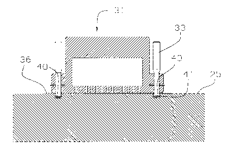
FIG 7 shows head of the applicator apparatus pushing soft plastic label onto
the
wood surface.
FIG 8 shows x sectional view taken along line 8-8 on FIG 6.
FIG 9 shows hard plastic strips being punched and disks of cut out hard
plastic
above the soft plastic label.
FIG 10 shows soft plastic being formed and pushed into the wood by the hard
disks that are being pushed by punches.
FIG 11 shows punches being from the holes that were punched into the wood.
FIG 12 shows applicator apparatus being lifted from the wood surface into
which
a soft plastic label is securely fastened.
3

CA 02334682 2001-03-02
DETAILED DESCRIPTION OF TH PREFFERED EMBODIMENTS
FIG 1 shows application apparatus 20 consisting of the vacuum chamber 21;
pushing edges 22, strip of hard but pliable plastic 23 onto which is printed
identification
markings on the surface 24. Wood product 25 is in the proximity of the
application
apparatus 20. Edges 22 are part of the edge assembly 26 and they can move
relatively to
the housing 27 of the vacuum chamber 21. Vacuum is applied onto the strip 23
through
the holes 28. Atmospheric pressure will hold plastic label 23 in place as
shown.
FIG 2 shows plastic strip 23 firmly pressed onto the wood product 25 at this
point
the vacuum in the vacuum chamber 21 is disengaged and this cavity 21 is now
subjected
to the atmospheric pressure. If low vacuum is being used there is no real
requirement to
disengage vacuum at this point and low vacuum can be applied all the time.
Edges assembly 26 is now ready to be pushed towards the surface of the wood
product 25.
FIG 3 shows edges 22 pushing edges of the plastic label 23 into the wood
product
25. The assembly of the edges 22 and plastic label 23 will form grooves 28.
FIG 4 shows edges assembly 26 being pulled out of the indented grooves 28
while
the housing 27 is still pressing plastic label 23 firmly on the surface of the
wood product
25. Edge 29 of the plastic label 23 is engaged with the hole 28. Springiness
of the wood
25 will tend to close hole 28 resulting in further engaging of the plastic
label edge 29
with he hole 28.
4

CA 02334682 2001-03-02
FIG 5 shows application apparatus 20 being lifted to start next cycle where it
will
engage plastic label 23 by vacuum and deposit it to the next wood product 25.
Formed
plastic label 30 is shown firmly fastened to the wood product 25.
For example plastic label 23 can be made from semi rigid and yet pliable
plastic
material such as polypropylene. This material will bend easily and yet it will
retain
enough springiness to engage edge of the hole 28.
FIG. 6 shows application apparatus 31 positioned over the wood product 25.
Application apparatus 31 contains a vacuum chamber 32, punches 33 and strips
of hard
plastic 34. Vacuum is engaged through the holes 35 onto the soft and pliable
plastic label
36. Identification markings are on the surface 37 of the soft pliable plastic
label 36.
FIG 7 shows application apparatus 31 positioning plastic label 36 firmly onto
the
surface of the wood product 25. At this point vacuum in the cavity 32 can be
disengaged,
reduced and if at low value left on.
FIG 8 shows x section along lines 8-8 on the FIG 6. Application apparatus 1 is
shown in a x section where hard plastic strip is shown positioned above holes
38. Soft,
pliable plastic label 36 is shown in its relative position on the application
apparatus 31.
Punch 33 can be equipped on its lower end by a dimple or point 39 which will
force
plastic strip to slightly deform in a concave fashion. This point 39 can be
sharp or blunt
as shown.
Purpose of deforming cut disk in concave form is to allow spring back of the
cut
disk in the hole to further increase holding power of this disk against the
soft pliable
plastic and surface of the hole 28 in the wood 25.

CA 02334682 2001-03-02
FIG 9 shows punches 33 punching hard plastic strips 34 and producing hard
plastic disks 40. Soft pliable plastic label 36 is being firmly placed on the
surface of the
wood product 25. Further travel of the punches 33 will force plastic disks 40
to deform
soft pliable plastic label material into the wood product 25.
FIG 10 shows soft pliable plastic label 36 being formed and pushed into the
wood
product 25 into formed hole 41.
FIG 11 shows application apparatus 31 still holding label 36 in place while
punches 33 are being moved out of holes 41. Hard plastic disks 40 will
slightly
straighten to increase their diameter and securely wedge material of the soft
pliable
plastic label 36 into the holes 41.
FIG 12 shows application apparatus 31 being lifted from the wood product 25.
Hard plastic strips 34 will be indexed to position new material over holes 38
for the next
cycle. Pliable plastic label 36 is securely held in the holes 41 of the wood
product 25 by
the hard plastic disks 40. When wood product 25 will be dried holes 41 will
shrink and
further increase strength of the mechanical bond of the plastic disks 40.
As will be apparent to those skilled in the art in the light of the foregoing
disclosure, many alternations and modifications are possible in the practice
of this
invention without departing from the spirit or scope thereof. Accordingly, the
scope of
the invention is to be construed in accordance with the substance defined by
the
following claims.
What is claimed is:
6

Representative Drawing
A single figure which represents the drawing illustrating the invention.
Administrative Status

2024-08-01:As part of the Next Generation Patents (NGP) transition, the Canadian Patents Database (CPD) now contains a more detailed Event History, which replicates the Event Log of our new back-office solution.

Please note that "Inactive:" events refers to events no longer in use in our new back-office solution.

For a clearer understanding of the status of the application/patent presented on this page, the site Disclaimer , as well as the definitions for Patent , Event History , Maintenance Fee  and Payment History  should be consulted.

Event History

Description Date
Change of Address Requirements Determined Compliant 2002-10-15
Inactive: Office letter 2002-10-15
Inactive: Withdraw application 2002-09-12
Inactive: Correspondence - Formalities 2002-09-12
Change of Address or Method of Correspondence Request Received 2002-09-12
Inactive: Withdraw application 2002-09-12
Application Published (Open to Public Inspection) 2002-09-02
Inactive: Cover page published 2002-09-01
Inactive: Incomplete 2002-08-13
Inactive: First IPC assigned 2001-03-23
Inactive: Filing certificate - No RFE (English) 2001-03-09
Filing Requirements Determined Compliant 2001-03-09
Application Received - Regular National 2001-03-08

Abandonment History

There is no abandonment history.

Fee History

Fee Type Anniversary Year Due Date Paid Date
Application fee - small 2001-03-02
Owners on Record

Note: Records showing the ownership history in alphabetical order.

Current Owners on Record
MIROSLAV HARCUBA
Past Owners on Record
None
Past Owners that do not appear in the "Owners on Record" listing will appear in other documentation within the application.
Documents

To view selected files, please enter reCAPTCHA code :


To view images, click a link in the Document Description column. To download the documents, select one or more checkboxes in the first column and then click the "Download Selected in PDF format (Zip Archive)" or the "Download Selected as Single PDF" button.

List of published and non-published patent-specific documents on the CPD .

If you have any difficulty accessing content, you can call the Client Service Centre at 1-866-997-1936 or send them an e-mail at CIPO Client Service Centre.


Document
Description 
Date
(yyyy-mm-dd) 
Number of pages   Size of Image (KB) 
Representative drawing 2002-08-07 1 35
Abstract 2001-03-01 1 29
Description 2001-03-01 6 220
Drawings 2001-03-01 9 428
Filing Certificate (English) 2001-03-08 1 161
Correspondence 2001-02-19 1 27
Correspondence 2002-08-06 1 19
Correspondence 2002-09-11 1 49
Correspondence 2002-10-14 1 13
Correspondence 2002-10-14 1 16