Language selection

Search

Patent 2334732 Summary

Third-party information liability

Some of the information on this Web page has been provided by external sources. The Government of Canada is not responsible for the accuracy, reliability or currency of the information supplied by external sources. Users wishing to rely upon this information should consult directly with the source of the information. Content provided by external sources is not subject to official languages, privacy and accessibility requirements.

Claims and Abstract availability

Any discrepancies in the text and image of the Claims and Abstract are due to differing posting times. Text of the Claims and Abstract are posted:

  • At the time the application is open to public inspection;
  • At the time of issue of the patent (grant).
(12) Patent: (11) CA 2334732
(54) English Title: DISPENSING DEVICE FOR LUBRICANT COMPOSITION
(54) French Title: DISPOSITIF DE DISTRIBUTION POUR COMPOSITION LUBRIFIANTE
Status: Deemed expired
Bibliographic Data
(51) International Patent Classification (IPC):
  • F16N 7/12 (2006.01)
  • B65G 45/02 (2006.01)
(72) Inventors :
  • GOMEZ DIAZ, JESUS (Argentina)
  • MENDEZ, JOSE (Argentina)
(73) Owners :
  • DIVERSEY, INC. (United States of America)
(71) Applicants :
  • UNILEVER PLC (United Kingdom)
(74) Agent: BERESKIN & PARR LLP/S.E.N.C.R.L.,S.R.L.
(74) Associate agent:
(45) Issued: 2007-12-18
(86) PCT Filing Date: 1999-06-10
(87) Open to Public Inspection: 2000-01-13
Examination requested: 2004-05-17
Availability of licence: N/A
(25) Language of filing: English

Patent Cooperation Treaty (PCT): Yes
(86) PCT Filing Number: PCT/EP1999/004041
(87) International Publication Number: WO2000/001979
(85) National Entry: 2000-12-11

(30) Application Priority Data:
Application No. Country/Territory Date
M 98 01 03216 Argentina 1998-07-02

Abstracts

English Abstract


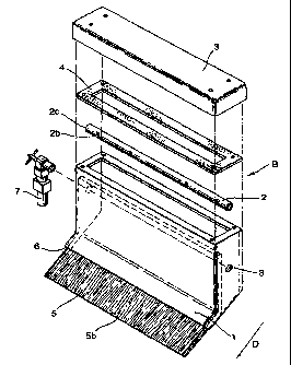
A lubricant composition dispensing device comprising
a hollow body (1) which houses a collecting pipe (2) is
described. The collecting pipe has perforations (2b) that
allow for lubricant composition to extend to a high density
felt cloth (5) which contacts and delivers the lubricant
composition to conveyor belts.


French Abstract

L'invention concerne un dispositif de distribution pour composition lubrifiante, comprenant un corps creux (1) qui renferme un tuyau de collecte (2). Ce tuyau de collecte possède des perforations (2b) qui permettent à une composition lubrifiante de s'étendre vers un drap feutré (5) à densité élevée, celui-ci étant en contact avec les bandes transporteuses et leur distribuant la composition lubrifiante.

Claims

Note: Claims are shown in the official language in which they were submitted.


6

Claims


1. A lubricant composition dispensing device (B),
comprising a hollow body (1) which houses in the interior
thereof a collecting pipe (2) having a plurality of
transverse perforations (2b), and an absorbing felt cloth
(5), which partially protrudes from said hollow body
through a bottom opening thereof (6).


2. The lubricant composition dispensing device according
to claim 1; further comprising a cover (3) and a seal (4)
wherein the cover is mounted to a top portion of the hollow
body (1) and the seal is positioned between the top portion
and the cover.


3. The lubricant composition dispensing device according
to claim 1, further comprising a lubricant composition
injection valve (7), the lubricant composition injection
valve mounted external to the hollow body (1) and connected
to the collecting pipe (2).


4. The lubricant composition dispensing device according
to claim 1, wherein the lubricant composition dispensing
device is mounted to a conveyor.


5. The lubricant composition dispensing device according
to claim 4 , wherein the conveyor comprises a chain (C).

6. The lubricant composition dispensing device according
to claim 5, wherein the chain is lubricated by the
lubricant composition discharged by the lubricant
composition dispensing device.


7

7. The lubricant composition dispensing device according
to claim 4 wherein the conveyor is used in the bottling
industry.


8. The lubricant composition dispensing device
according to claim 4 wherein the absorbing cloth (5)
consisting of high density felt has an external portion
(5b) that contacts the chain.


9. The lubricant composition dispensing device
according to claim 8, wherein the external portion (5b)
delivers lubricant composition to the chain by contact.


Description

Note: Descriptions are shown in the official language in which they were submitted.


CA 02334732 2000-12-11

WO 00/01979 PCT/EP99/04041
1

DISPENSING DEVICE fOR LUBRICANT COMPOSITION
Field of the Invention

This invention relates to a dispensing device for lubricant
compositions. More particularly, the invention is directed
to a dispensing device that distributes a lubricant
composition to the belts of conveyors used in a variety of
industries, includir.Lg the bottling industries.

Background of the Invention

At bottling plants, for example, bottles are conveyed by
means of a conveyor which typically comprises conveyor
belts made of stainless steel, iron or plastic chains
having side railings which-hold the bottles on the
conveyor. Conventior;al bott:ling lines consist of a large
quantity of these types of chains which make up the belts
of the conveyors.

The surface of the chains must be lubricated for bottles
being transported on the conveyor to remain in position.
Such lubrication, therefore, prevents the bottles from
falling off the conveyor when, for instance; a machine
failure or temporary halt of the conveyor causes the
bottles to stop. This is true because lubrication allows
for the chains of the conveyor belt to proceed in motion
(in a friction-free manner) without causing the motionless
bottles to fall.

In the absence of appropriate lubrication, however, the
chains of the conveyor belts can break or be cut, causing
bottles to fall, loose their contents and/or break.
Moreover, due to stress, motor reducers of the conveyors
would break down or burn out their coils. Thus, improperly
lubricated conveyors can cause in a production standstill,


CA 02334732 2000-12-11

WO 00/01979 PCT/EP99/04041
2

resulting in important economic losses in the bottling
industry.

Conventional processes for lubricating bottling lines are
generally performed as follows:
The equipment, with lubricant composition supply, delivers
the lubricant throuqh pipes attached to a lateral of the
conveyor. From the pipes, the composition is delivered to
collectors, which consist of a% bar and injection holders.
The injectors have holes of sizes that vary from 0.30 to
0.50 mm, wherein one injector is located at the center of
each conveyor belt allowing for the homogeneous
distribution of lubricant composition throughout the
conveyor.
Such conventional pr.ocesses, however, exhibit several
problems and disadvantages. This is true because injection
holes often are easily clogged. Further, much of the
lubricant composition, like 70%, falls to the floor before
being distributed by the bottles on the conveyors. Thus,
only 30% of the lubricant composition is used, with the
remainder being wasted and creating environmentally
unfriendly conditions. Still further, conventional
processes contain jets that spray a mist of the lubricant
composition that often contaminates the product being
bottled.

It is of increasing interest to produce a dispensing device
to apply or dispense a lubricant composition, in the
absence of the above-described problems. The present
invention, therefore, is directed to a lubricant
composition dispensing device that comprises a hollow body,
which houses in the interior thereof a collecting pipe
exhibiting a plural:Lty of transverse perforations, and an
absorbing felt cloth preferably consisting of high density


CA 02334732 2000-12-11

WO 00/01979 PCT/EP99/04041
3

felt, which partially protrudes from said hollow body
through a bottom opening thereof.

Summary of the Invention

The present invention is based on a new dispensing device
which does not function through hole plates. The dispensing
device consists of a hollow body made of stainless steel,
plastic or other material, having dimensions that vary
according to the chains supplying each particular conveyor.
The hollow.body houses an absorbing cloth, in such a way
that one of the ends of the absorbing cloth protrudes from
the bottom of the hollow body. The dispenser of this
invention is instal-led at each of the heads of the
conveyors. The dispenser is attached to the conveyers by
means of stainless clamps in such a way that the cloth
protrudes from the hollow body and rests on the chains of
the conveyor.

The dispenser is fed, similarly to dispensers known in the
art, by pipes which are attached to the sides of the
conveyor. Lubricant composition will be supplied so as to
feed the dispenser's hollow body, and the composition will
be absorbed by the cloth, which in turn will transfer the
lubricant composition to the conveyor chains by contact.
This novel lubricant composition dispensing device exhibits
the following advantages when compared to known systems.

The dispensing device of the present invention is not
clogged by the composition being dispersed, resulting in
savings in terms of workmanship. Furthermore, 100% of the
lubricant composition is used due to the fact that the
chain itself carries the composition thereby preventing
splashing of the composition onto the floor. Moreover, the
- -----------


CA 02334732 2000-12-11

WO 00/01979 PCT/EP99/04041
4

dispensing device of the present invention allows for
dosing of the composition in a manner that is homogeneous
throughout all of the conveyor chains being lubricated.
Thus, the superior dispensing device of this invention
results in the application of lubricant composition onto
conveyor chains at high concentrations and with low
consumption. Also, the device of this invention allows for
low water consumption, and since lubrication with the
device of this invention is more concentrated, the need for
overflows is eliminated.

Brief Description of the Drawings

Fig. 1 schematically shows a conventional lubricant
dispensing system;
Fig. 2 schematically shows the dispensing device according
to the invention, arranged on a conveyor chain.
Fig. 3 shows an exploded view of the dispensing device
according to the invention.
Detailed Desaripti= of the Preferred Embodiments

Fig. 1 shows a conventional system of lubrication by means
of injectors A which spray lubricant to chain C.
Fig. 2 shows dispensing device B according to the
invention, arranged over chain C, in its operating
position.

Fig. 3 is an exploded view of dispensing device B, where it
can be observed that: the dispensing device B is formed by a
hollow body 1 which houses in the inside thereof a
collecting pipe 2 which exhibits transverse perforations 2b
and internal end threads 2c, a cover 3 of said body 1, a
seal 4, an absorbinq cloth 5 consisting of a high density


CA 02334732 2000-12-11

WO 00/01979 PCT/EP99/04041

felt, the major part. thereof being inside hollow body 1,
and protruding therefrom through an opening 6, forming a
supporting overlap over chain C. There is also shown an
injection valve 7, u,rhich is external to the hollow body 1
5 and connected to encl threads 2c for the introduction of
lubricant into collecting pipe 2.

Obviously, the length of body 1 may vary according to
conveyor specifications, and should it be necessary, more
than one body 1 may be joined by outlet hole 8 of
collecting pipe 2.
When assembled at its place of operation, liquid lubricant
composition is injec:ted through valve 7 into collector pipe
2. The composition passes through perforations 2b made on
said collecting pipe and fills hollow body 1. Subsequently,
the liquid lubricant. composition soaks felt cloth 5 and
proceeds towards the external free end portion 5b of said
cloth 5.
The external portior., 5b of cloth 5 rests on chain C and as
the absorbing cloth 5 is displaced in the direction of
arrow D, the free end portion 5b of the cloth 5 delivers
lubricant composition onto the chain C in a quantity
necessary for the appropriate lubrication thereof.

Representative Drawing
A single figure which represents the drawing illustrating the invention.
Administrative Status

For a clearer understanding of the status of the application/patent presented on this page, the site Disclaimer , as well as the definitions for Patent , Administrative Status , Maintenance Fee  and Payment History  should be consulted.

Administrative Status

Title Date
Forecasted Issue Date 2007-12-18
(86) PCT Filing Date 1999-06-10
(87) PCT Publication Date 2000-01-13
(85) National Entry 2000-12-11
Examination Requested 2004-05-17
(45) Issued 2007-12-18
Deemed Expired 2014-06-10

Abandonment History

There is no abandonment history.

Payment History

Fee Type Anniversary Year Due Date Amount Paid Paid Date
Application Fee $300.00 2000-12-11
Maintenance Fee - Application - New Act 2 2001-06-11 $100.00 2000-12-11
Registration of a document - section 124 $100.00 2001-04-17
Maintenance Fee - Application - New Act 3 2002-06-10 $100.00 2002-05-24
Maintenance Fee - Application - New Act 4 2003-06-10 $100.00 2003-05-28
Registration of a document - section 124 $50.00 2003-07-31
Request for Examination $800.00 2004-05-17
Maintenance Fee - Application - New Act 5 2004-06-10 $200.00 2004-05-28
Maintenance Fee - Application - New Act 6 2005-06-10 $200.00 2005-05-24
Maintenance Fee - Application - New Act 7 2006-06-12 $200.00 2006-05-29
Maintenance Fee - Application - New Act 8 2007-06-11 $200.00 2007-05-28
Final Fee $300.00 2007-09-27
Maintenance Fee - Patent - New Act 9 2008-06-10 $200.00 2008-05-20
Maintenance Fee - Patent - New Act 10 2009-06-10 $250.00 2009-05-19
Registration of a document - section 124 $100.00 2010-05-06
Maintenance Fee - Patent - New Act 11 2010-06-10 $250.00 2010-05-17
Maintenance Fee - Patent - New Act 12 2011-06-10 $250.00 2011-05-17
Maintenance Fee - Patent - New Act 13 2012-06-11 $250.00 2012-05-17
Owners on Record

Note: Records showing the ownership history in alphabetical order.

Current Owners on Record
DIVERSEY, INC.
Past Owners on Record
GOMEZ DIAZ, JESUS
JOHNSONDIVERSEY, INC.
MENDEZ, JOSE
UNILEVER PLC
Past Owners that do not appear in the "Owners on Record" listing will appear in other documentation within the application.
Documents

To view selected files, please enter reCAPTCHA code :


To view images, click a link in the Document Description column. To download the documents, select one or more checkboxes in the first column and then click the "Download Selected in PDF format (Zip Archive)" or the "Download Selected as Single PDF" button.

List of published and non-published patent-specific documents on the CPD .

If you have any difficulty accessing content, you can call the Client Service Centre at 1-866-997-1936 or send them an e-mail at CIPO Client Service Centre.


Document
Description 
Date
(yyyy-mm-dd) 
Number of pages   Size of Image (KB) 
Description 2000-12-11 5 241
Representative Drawing 2001-03-30 1 16
Abstract 2000-12-11 1 78
Claims 2000-12-11 2 65
Drawings 2000-12-11 2 78
Cover Page 2001-03-30 1 43
Claims 2006-08-23 2 54
Representative Drawing 2007-11-21 1 21
Cover Page 2007-11-21 1 48
Correspondence 2001-03-09 1 24
Assignment 2000-12-11 4 158
PCT 2000-12-11 9 385
Assignment 2001-04-17 3 90
Assignment 2003-07-31 5 218
Prosecution-Amendment 2006-02-24 2 36
Prosecution-Amendment 2004-05-17 1 36
Prosecution-Amendment 2004-07-05 1 38
Prosecution-Amendment 2006-08-23 3 51
Correspondence 2007-09-27 1 29
Assignment 2010-05-06 9 719
Assignment 2010-05-07 12 627