Note: Descriptions are shown in the official language in which they were submitted.
CA 02334779 2000-12-08
WO 00/67933 PCT/GR00/00009
1
METHOD AND MACHINE FOR THE MANUFACTURE OF
METALLIC FRAMES FIR INNER SPRING MATTRESSES
The present Invention Alteration refers to invention with No960100215
which is dealing with a method and a machine for the manufacture of metallic
frames for the Inner Spring Mattresses.
It is known that metallic frames, which are made of round wire or flat round
wire
and the ends of which are connected rigidly together with a plate, are
necessary for
1o the manufacture of inner spring mattresses for the circumferential support
of the
springs. The said closed frames have the shape of the mattress under
construction.
The most widely used method of construction of such metallic frames
necessitates
the use of at least two machines, she design of which is based on a method for
the
formation of round wire or flat wire, the stages of which follows the
following
series : feeding and straightening of the round wire or of the flat wire,
bending into
the final shape of the fame, cut-ol:f, collection and transportation of the
open frame
manually to a connective machine: and finally, connection of the two ends with
a
metallic clip.
Alternatively, the connection of th.e two ends is performed with a small tube
instead
of the plate or with butt welding.
The principal drawbacks of the existing technology are : two machines are used
: the
straightening-bending machine and the connective machine which are independent
of each other. For this reason, manual work is necessary for the collection
and
transportation of the open l:rame to the connective machine. The worker
collects
the difficult to handle open frame, which bends easily, transports it to the
connective machine, supplies the machine with the. said open frame suitably
3o positioned, activates the machine., which connects the two free ends of the
open
fame with a metallic clip or a small tube or by butt welding in the sequel the
workex
collects the closed frame and repeats the above procedure for each new frame
for
construction. It must be emphasi?:ed that the manual actions are usually
performed
by more than one worker for achieving a decent productivity.
During bending all the sides of the akeady manufactured frame rotate with
respect
to one of its corners. As the frune is still open during the bending process,
it
exhibits a high degree of flexibility. For this reason the speed of rotation
of the
frame and consequently the speed of the bending is low. The movement of the
0 open frame requires a large space and leads to an horizontal arrangement of
machine of large sizes, e.g. for rotting a frame cross section of 2 meters x 2
meters
with respect to one of its corners, a free circular space of a radius equal to
ita
diagonal is required, i.e. of 2,f3 meters. The bending step in an horizontal
arrangement after the two ends of frame under construction is free leads to
low
speeds of feeding of the round wine or flat wire.
CA 02334779 2000-12-08
WO 00/67933 PCT/GR00/00009
2
Due to the flexibility and due to tt~e fact that the two ends of the frame are
free, the
handling performance is especially difficult, both during the collection and
during
suitable positioning of the two ends in the connective machine. This is the
principal
reason that until today, the comply°te automation of the production of
open frames
for inner spring mattresses has not been possible and for the necessity for
manual
work by the personnel.
It is evident that this manufacturing process leads to a waste of time, high
labour
costs and low productivity.
i0
The aim of the present invention is to solve the problems described above by
offering a method which permits the automated manufacture of metallic frames
for
inner spring mattresses in a simple and quick manner.
The objective of the present invention is to offer an arrangement which
renders the
automation of the manufacture of metallic frames for inner spring mattresses
possible, and which is simple in its design, reliable in its operation and
easy to use.
More details of the arrangement according to the Invention 960100215 will be
made
2o understood by the description below of a particular application of it. A
method of
application of the invention is described in the sequel, with references to
drawings
which explain a particular implementation, are
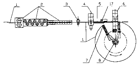
win 1 is a side view and partial longitudinal cut of the machine for the
manufacture of metallic frames for inner spring mattresses.
rawin 2 is a top view and partial cut.
Drawing 3 is a cross sectional view.
Drawing ~ is a side view of the part with the connective mechanism.
Drawing_5 is a cross sectional cut of the machine.
j2,~~ illustrates an example of the connection of the two ends of a metallic
fume for inner spring mattresses of round wire of a circular cross section
constructed by the machine according to the present invention.
D~gl illustrates an example of the connection of the two ends of a metallic
.to frame for inner spring mattresses of round wire constructed by the machine
according to the present invention..
D~ $ illustrates another implementation of the connection of the two ends of
a metallic frame for mattresses fitted with springs made of flat wire,
constructed by
.ts the machine according to the press°nt invention.
CA 02334779 2000-12-08
WO 00/67933 PCT/GR00/00009
3
Drawing 9 illustrates an example of a metallic frame for inner spring
mattresses
constructed by the machine according to the present invention.
Drawing 10 illustrates another implementation of a metallic frame for inner
spring
mattresses constructed by the machine according to the present invention.
Drawing 11 illustrates another implementation of a metallic frame for
mattresses
fitted with springs constructed by tlhe machine according to the present
invention.
to Drawing_12 illustrates all the stages of the connection of the two ends of
the frame
in a cross sectional cut of the conner_tive mechanism.
Drawin~,13 is a front view of the connective mechanism.
Following its straightening, the round wire or the flat wire (1) is fed with
the
assistance of a rotary mechanism (8), an open elliptical or circular frame is
produced
with a length equal to the circumference of the frame under construction.
Following
feeding of the necessary round wire or flat wire (1) the cut-off is performed
with
simultaneous formation of incisions in the surface of the round wire or flat
wire (1)
2o using a cutter (4). Alternatively, the formation of the ends of the round
wire or flat
wire may be performed by a formal g device prior or following the cut -of~ The
two
ends of the circular frame come into contact with the assistance of the rotary
mechanism (8) into a connective mechanism (G) where they are rigidly retained
appropriate position by tow jaws (:22,23) in the. The two ends, being in
contact, are:
wound by the connection plate (14) which comes from a spinning wheel (10), and
which is fed by a mechanism with an adjustable step (15) and is then suitably
pressed so that the material of the .connection plate (14) penetrates into the
incisions
of the ends of the round wire or flat wire (1). In this manner the strong
connection
of the two ends of the frame under construction is ensured. The closed frame
3o produced is transported by an arm (13) to the bending unit (9) where it is
bent to
particular positions and at particular angles so that a frame of a desirable
shape is
produced. If the frame is made of round wire (1), the said round wire (1) is
formed
into an ellipse or circle bent across; the axis with the smaller inertia
torque and then
at the bending unit (9) it is bent at the suitable angle, usually at right
angles to the
plane of the initial elliptical or circle.
The above mentioned method is :implemented, in the machine the description of
which follows. The operation of the individual mechanisms is controlled by a
microprocessor. The round wire or flat wire (1) is fed and straightened in the
4o feeding-straightening mechanism (2), whereas the fed length of the said
round wire
or flat wire (1) is measured by the measuring device (3}. In the sequel, the
material
passes through the cutter (4) which is suitably formed so that shaping of the
ends of
the round wire or flat wire (1) :is performed along with the cut-off and is
fed
through the guide (5) towards the connective mechanism. In the outlet of the
said
connective mechanism the jaws (7) of the rotary arm (8} is located. The round
wire
CA 02334779 2000-12-08
WO 00!67933 PCT/GR00/00009
4
or flat wire (1) is secured by the jaws ('~, the rotary arm (8) rotates
simultaneously in
co-ordination with the feeding-straightening mechanism (2) and transports the
jaws
('~ to the across side of the connecaive mechanism (G) without yet being in
contact
with it, forming an open elliptical or circular frame. After the length of the
fed
material is equal to the circumference of the frame under construction cut-off
and
suitable forming of the ends ocmrs in the cutter (4), whereas the edge of the
produced frame and the other edge of the subsequent frame are formed. The
round
wire or flat wire (1) of the frame produced is then fed by the existing round
wire or
flat wire (1) of the subsequent frame in the connective mechanism (G) via the
guide
to (5), which consists of two parts : a l:~ed and a moving one, suitable for
free rotation
around the pin {17). The feeding stops after the ending of the round wire or
flat
wire (1) of the frame under production reaches a particular position of the
mechanism (G). There, the round «vire or flat wire (1) is secured by a jaws
(23) so
that it remains stationary. The necv round wire or flat wire (1) of the
subsequent:
frame moves backwards by a particular length so that it frees the moving one
part of
the guide (5). Then, the jaws (7) moving along a curve line by the rotary arm
(8)
brings this second edge of the open frame into contact with the first, which
is
retained steadily by the jaws (23) at the connective mechanism (G) displacing
the part:
of the guide (5) moving freely around the pin (17). The edge of round wire or
flat:
2o wire (1) held by the jaws ('~ is secured by a second jaws (22) and thus the
two ends
of the round wire or flat wire (1) are rigidly held and in contact with each
other at a.
suitable position of the connective :mechanism {G).
The connection plate (14) coming from the wheel (10) is fed by the feeding
mechanism (15) with an adjustable steady step to the connective mechanism (G)
at
right angles to the round wire or flat wire (1) of the frame under
construction and at
a length depending on the circumference of the said round wire or flat wire
(1)
{Drawing 12A) ; it then intersects at the respective length with the
assistance of a
fixed (20) and or a moving one cutter (19) which, moving upwards as
illustrated in
(Drawing 12A) and with the assistance of the downwards moving shaper (18) it
bends the connective plate (14) aground the round wire or flat wire (1)
(Drawing
12B). in the sequel, the upper sh;iper (18) moving upwards frees the
connection
space, a second shaper (21) comes from the side to the connection area
(Drawing
12G~ moving along an arc, the other shaper (18) moves again downwards pushing
the second shaper (21) which then shapes the connective plate (14) so that the
two
ends of the said plate (14) converge to the plane of the longitudinal symmetry
axis
of the round wire or flat wire (1) (Drawing 12D). In the subsequent phase, the
upper shaper {18) moves upwards, the second shaper (21) frees the connection
space, moving to the side along an arc, the upper shaper again descends and
presses
o the round wire connection (14) (Drawing 12E) hardly so that the material of
they
said connective plate (14) penetrates into the incisions of the round wire or
of the
flat wire (1) of the frame under construction resulting in a strong connection
of the
ends of the frame as illustrated in drawings G and 7. Alternatively, the
connection
can be performed by hooking the suitably shaped ends as illustrated in the
example.
of Drawing 8 or by butt welding or by glue and suitable plate or small tube.
Thf~
CA 02334779 2000-12-08
WO 00/67933 PCT/GR00/00009
frame which is now closed is transported by the arm (12) to the bending
mechanism (9) located across of the connective mechanism (G). This consists of
the
feeding -length measurement sheaves (11) and the bending sheaves(12). 'The
closed
frame is fed and curved at predetermined positions and angles so that the
frame
required is produced. In particular, should the material of the frame is round
wire
(1), the bending mechanism is positi~.oned so that the round wire (1) is
curved under
a suitable angle, usually at right angles to the plane of the closed
elliptical or circular
frame at particular angles and predetermined positions. After the closed frame
is
transported with the assistance of the arm (12) to the bending mechanism (9),
the
1o production of the next frame starts in parallel with the bending of the
frame under
construction and thus productivity of the machine is maximized.
To the above described method there are a number of disadvantages.
The cutting and the Grooving of the wire ends is taking place on the same
press so
required a lot of tool strength and a. lot of tools where is taking place.
Also, in order
to transport the beginning of the wire (Round or Flat) in the connection
mechanism
(G) the looping arm (8) is used where a gripper (7) is fitted at its end. This
configuration requires for the wire to stop at the position where the gtipper
('~ is
located. Then, the activation of the: gripper is required in order for the
wire to be
trapped inside. The gripper's activation is achieved with the use of Hydraulic
or
Pneumatic Piston which is required to be located along side the looping Arm
(8). In
addition, the oil of Air Supply tube is required to be rotated as well. On
completion
of the hand over of the beginning of the wire to the gripper (22) a return
activation
mechanism of the looping Arm (8) must be initiated in order for the looping
Arm
(8) to be returned to its original position.
All these require a very complicated mechanism in order for the method to be
materialized.
3o Also, the fact that the pressing tool (2I) has to form an Arc during its
operation in
order to come side ways to the pressing Area (12c) and the one pressing tool
(18)
requires to be more downwards pushing the second pressing tool (21) which
forms
the clipping making the possibility of very often breakages of the tools in
addition to
the fact that if the cutting tool breaks the whole system needs to be changed.
According to the present invention of the transportation of the beginning of
the
wire (Round or flat) is achieved by its own movement because it is inserted in
a
groove (25), which belongs to the guide {24). The groove is covered by a cover
(2G),
Drawing 1G. The round or flat wire by entering the position 24a, Drawing 15 of
the
guide because of the continuous fey°ding ends up at the position 24b
where 2 rollers
(31) and (32) are engaging it (Drawing 14,15) so its location and stoppage.
When the
beginning of the wire reaches the cover 2G, Drawing 1 G by its move frees the
groove
(25), (Drawing 1 G and 1 Gb) so th.e wire (Round or Flat) free now can take
the
required length without restriction.
CA 02334779 2000-12-08
WO 00/67933 PCT/GR00/00009
6
With the completion of the required length of the frame the cutting and the
grooving of the wire as well as the feeding of the cut length with its
beginning of the
new frame to the pressing mechani.5m (16) where the end of the frame is
trapped
from the gripper (23}, (Drawing 13). 'Then the beginning of the new frame is
retracting allowing the rollers (31) and (32) to rotate so feeding the ends to
get
joined together. Then the gripper (22), Drawing 13 is closing.
The two wire ends are winding with the clipping material (14) which is getting
unwinded continuously by a coil/swift (10) which is advanced from feeding
adjustable step mechanism(15).
to
The clipping material (14) is suitably pressed so to enter the grooves at the
wire ends
of the produced frames. When the wire end has been clipped the loop is
transported.
to the bending mechanism (9) through a transportation mechanism (13) where
the:
required frame is produced.
The big advantage of this invention is that the entrance of the wire (Round
and flat)
at the groove of the guide (24) is moving and arriving without secondary
mechanism
at a point before its entrance on th~° clipping mechanism without
requiring the initial
length measurement stoppage to the gripper to catch it and to start feeding
again.
With this method it is gained tune on the production of the frames and all
they
mechanism is simplified for the catching, transportation and entrance of the
beginning at the processing mecha~~ism.
In addition according to the present invention the pressing tool mechanism
(21}
which has to form an Arc during its operation in order to come sideways in
addition
to the auxiliary clipping tools (1f3,20) (Drawing 12) are all located on to a
tool
magazine (Drawing 1'7) which is moving only perpendicular to the wire line
with
intermediate positions which corrc~_spond to the required tool needed to
perform a
3o job. Thus the possibility of tool breakages is minimized because the action
of the
operating clipping tools is only perpendicular and not in the form of an Arc.
Also, according to the present invention the cutting of the round or flat wire
and
the shaping of the wire ends is performed on two separated hydraulic presses
unlike
before that both operations were performed at the same time on a single press
(4).
This method ensures better tool wear and better product quality.