Note: Descriptions are shown in the official language in which they were submitted.
CA 02334928 2000-12-13
13-DEC-00 17:18 FROM:H6F LEEDS +44 113 230 4702 70:0016046875756 PRCE:004~050
Wd 99167632 P~TIGE9910ISZ0
ANAZ,"YSZB of LzQVID SAMPLES
The present invention relates- to the analysis of liquid
media to determine the presence, absence or concentration
of a species of interest. The species of interest may be
an element or molecule or other chemical species and may
include species of biological or industrial orig~.n. The
invention relates in particular to methods and apparatus
~.0 for carryir_g out such analyses and is especially
applicable to point-of-sampling testing,
In many situations whexe analysis of a ligui.d (or solid)
I
medium has been required it has been necessary to take a
sample of the medium and to forward the sample to a .
specialised laboratory for analysis. This is '
disadvantageous in terms of cost (for example because
highly trained technicians and expensive instrumentation
I
are required to perform the analysis? and because of the
I
time delay befoxe the results of the analysis are
obtained. Thus, for example, in many manufacturing i
processes results from the analysis of a sample are
required immediately in order to check, and if ,necessary
adjust, the process parameters.
. Ideally, in order for analysts at. the point-of-sampling '
to be successful, accurate results must be obtainable
with equipment which is as simple and robust as possible,
capable of carrying out repeated analyses and which
requires the minimum level of skip and input from the
operator. The present invention seeks to obviate ur
reduce Che abcve mentioned disadvantzges.
_ ..w......~,...~ ~_..._... .-.-. -w..~,.....~.~.-.-..~,_w--...~.~._-
_._~...,...~_.~-...._ .... .
CA 02334928 2000-12-13
13-DEC-00 17:18 FROM:HGF LEEDS +44 113 230 4702 70:0016046875756 PAGE:003~050
wo W s~r,~z rcr~G~99i0a 8zo
z
The analysis procedures and apparatus of the invention
are applicable to a wide variety of species, but one
particular use relates to the determination of the
alcohol. content of an alcoholic beverage - e~.ther as a
~inished product or during the production process - using
an electrochemical sensor device.
It z.s known that the alcohol content of alcoholic
beverages (e.g. beer and wine) may be determined by
electrochemical sensor devices, e.g. enzyme based
amperametric sensors, which axe imarzersed in the beverage
for the purpose of ef~ectzng the measurement. There are i
however problems associated with such measuremer..ts. Far
example, the sensor may require a dissolved oxygen
content tin the liquid sample being analysed) greater
than that normally present in an alcoholic beverage. In
this respect, it is relevant to note that beer and wine
have a dissolved oxygen content of only about 10% of
potential saturated content. Furthermore, alcoholic
beverages such as beer and sparkling wine (e. g.
champagne) contain di$solved carbon dioxide which can
cause problemsWhen it forms bubbles on the working
9ur~aca of the sensor immersed in the liquid resulting in
an incorrect measurement. An additional problem is Ghat
carbon dioxide may generate a froth which may interfere
with measurements rec~uirixlg passage of a sensor through
the froth before it is immersed ~.n the underlying licuid.
The apparatus and procedures of the present invention
provide for imprpved sample preparGtion which, in
CA 02334928 2000-12-13
13-DEC-00 17:18 FROM:H6F LEEDS +44 113 230 4702 70:0016046875756 PACaE:005~050
WO 99167632 PCTIG899I018Z0
'~'° 3
particular, ovexcame the above disadvantages.
According to a fixst aspect _of the invention there is
provided a method of analysing a liquid sample to
determine a species of interest present or potentially
present thexein, the method includz.ng ~he steps of:
providizlg a sampling vessel having a main sample
chamber containing the liquid tc~ be analysed, a sample
analys~.s region having an aoenable and cloeable aperture
and a sample flow path between the main chamber and the
sample analysis region;
transferring at least a portion of Che licyuid to be
analysed from the main chamber to the sample analysis
region via the ~low path;y
providing a sensor device including a sensor and,
before or after said transfer of li
quad to the sample
analysis region, inserting the sensor device into the
sample analysis region through the said openable and
closable aperture; and
using the sensor device to make a mea9uremertt to
determine the species of interest.
:.,~.,.ik
Preferably, the main chamber also has an openable and
closable aperture through which the liquid sample may be
introduced into the main chamber.
"he determination to be carried out by thp metrod cf the
invention may be tc determine the ptese.~_ce or absenc° (or
CA 02334928 2000-12-13
13-DEC-00 17:19 FROM:HCaF LEEDS +44 113 230 4702 70:0016046875756
Pfa6E:006~050
WO 99J6'1b32 PCTJGH99I01820
4
at least absence above a certain concentzation or amount)
of the species of interest or the aotual concentration or
amount of the species.
S The vessel is preferably such that it allows for the
transfer of a predetermined volume of prepared sample
from the main sample chamber to the sample analysis
region.
It is an advantage of the invention that the main chamber
of the sampling vessel may be used for a sample
preparation step to yield a liquid sample which is in a
particularly suitable condition for effecting the
measurement using the sensor device. The sampJ.e
preparation step may be a physical or chemical process
carried out on a "precursor" of the liquid sample to be
determined by the sensor device in the sample analysis
region of the sampling vessel.
Thus, by way of example of a physical sample preparation
step, the method of the invention may be ezfected by ;
i
introducing into the main chamber (as the aforesaid ,
"precursor") a liquid which is then subjected to a sample
preparation step involving an exchange of gas between the
liquid and i,ts surroundings. The vessel may be such that
for liquid (e.g, beer or sparkling wine? generating a
. froth during the sample preparation step a major j
proportion of the froth =ernains in the main sample
chamber.
this sxci-iange may fcr example be for the rurpose of
CA 02334928 2000-12-13
13-DEC-00 17:19 FROM:HGF LEEDS +44 113 230 4702 70:0016046875756 PRCE:007~050
WO 99167632 PCTIGB99I01820
increasing 4he dissolved oxygen content of the liquid
and/or (in the case of a liquid containing dissolved CO=)
to reduce the dissolved carbon dioxide cor~tent. The
sample preparation step may for example involve shaking
5 of the vessel or spraying of the liquid in a manner which
effects the desired exchange of gas.
A further example of a physical sample preparation stsp
is a mixing (e. g. by agitation or swirling of the vessel)
of a Iiquid,(the aforesaid "precursor") introduced into
the main chamber. Thus, for example, the squeezed juice
from all segments of a citrus fruit (e.g. an oxange) may
be introduced into the main chamber and the vessel
swirled around to ensure thorough mixing of the juice to
ensure uniform concentration throughout the juice prior
to a portion thereof being provided (via the flow path)
to the sample analysis region for determination of the
i
compound of interest by the sensor device.
i I
I
Vaxious chemical sample preparation steps are also
possible. One example, involves introducing a
"precursor" liquid into the main chamber and adding
thereto solid or liquid reagents which react with the
"precursor" liquid to generate the liquid sample to be
provided in the sample analysis region for determination . ,
using the sensor device. The reagents may for example be
of a chemical (organic or inorganic) ox k~zological
nature, e.g. an enzyme.
A further possibility of a chemical sample preparation
step involves an extraction procedure erfectec i:~ the
CA 02334928 2000-12-13
"13-DECr00 17:19 FROM:HCaF LEEDS +44 113 230 4702 70:0016046875756
PA6E:008~050
WO 99167632 PCTIGB991018Z0
6
main chamber using a "precursor" liquid and an immiscible
extracticn phase into which the compound of interest (if
present in the "precursor") is extracted by partitioning. '
In this case, it is the extraction phase which prpvides
the liquid sample for transfer to the sample analysis
region fox determination by the sensor device. This
procedure is particularly useful for cases where the
"precursor" liquid contains an interferent of the
detection process, the interfexent remaining in the
extracted "precursor" liquid. It is of course also
possible to envisage extraction of the inter~erene~ from
the "precursor" liquid and transfer of the latter
(extracted) liquid to the sample analysis region.
A further possibility is that, by using appropriate.
volumes, Che extraction may function as a concentration
step.
A still further possibility in accordance with the
invention is for the °precursor" to be a solid or gas
whichvis introduced into the main chamber and subjected
to a chemical treatment to generate a liquid sample
(potentially containing the compound of interest) for
transfer to C.he sample analysis region.
In preferred embodiments of the invention, the vessel is
in the form o~ a battle in which internal walls define a
minor chamber which farms the sample analysis region as
an upper region of the bottle and further ?efine a
passageway Tor providing the flow path co provide the
cornmunica~ion between a lower region oL the mai:~ c.".a:'~e=
CA 02334928 2000-12-13
'13-DECr00 17:19 FROM:HCaF LEEDS +44 113 230 4702 70:0016046875756
PFICaE:009~050
WO 99161b32 PCTIG899/01820
7
and an upper region or the minor chamber, the apertures
of the main and minor chambers each being located at the
tap of the bottle. A bottle ~of this type is preferably
esqueezable" to allow for the sample liquid to be
analysed to be provided, in the main ( sample preparation)
chamber and for the bottle to be squeezed to transfer a
portion of the liquid sample to the minor (sample
analysis) chamber. Such a bottle may, for example, be of
the type disclosed in EP-A-0'010 965 (Hettix). ,,
14
Alternatively, the sampling vessel may comprise a main
chamber provided with a V-shaped tubular arm defining the
aa:nple analysis chamber.
The sensor device used for effecting the measurement may
for example be an electrochemical sensor, e.g. of the
type incorporating an enzyme electrode. In preferred
embodiments of the invention, the sensor' is an enzyme
based amperometric sensor which may. for example, be in
ZO planar or needle-like form. "The invention does however
extend to the use of non-enzymic and non-electrochemical
sensors, e.g. colorirnetric "dipsticks'.
The method of the invention preferably uses a sensor
device on or in which the sensor is mounted and which is
such that it (the sensor device) may be supported
relative to the sample analysis region so that the sensor
extends by a predetermined distance into that region to
provide fcr a known depth c~f immersior. of the sensor in
3 0 the l.~quid sample to be analysed . "'he sensor de'lice is
preferably such that a sensor is removably ~:ounted
......._._. _.._ . . .. . ~. . . .-.........~.~........~..~._..w..
CA 02334928 2000-12-13
,13-DEC-00 17:20 FRDM:HGF LEEDS +44 113 230 4702 70:0016046875756 PA6E:010~050
WO 99167632 PCTIG$9910I820
9
thereon. This allows the use of disposable sensors. The
sensor device may, for example, comprise an enlarged :~.ead
portion connected to an elongate finger along which the
sensor extends. The sensor device may for example
incorporate a pl~srality of sensors for determining '
different analyzes of interest in the liquid sample. The
sensor device preferably also comprises a temperature
sensor far immersion in the liquid whereby compensation
may be made for the temperature of the.sarnple.
A second aspect of the invention provides a component
which ensures that the sensor is removably located in a
predetermined location in the sample chamber. Tn this
way, it is possible to eliminate any variation in the
depth of insertion of the sensor in the liquid sample,
which variations could affect the accuracy of the
analysis. This component also serves to protect the
sensor from mechanical damage, in use. Accordingly, this
aspect of the invention provides a support component for
supporting a sensor devz,ce incorporating a ser_sor such
that the sensor is operatively maintained in a
predetermined relation to a vessel far containing. a
liquid , sample, the support component comprising a
generally tubular body portion, at least one orifice,
formed in the body portion, for the ingress of liquid,
first mounting means operative to co--operate with the
vessel so that the body portion operatively lies .in a
predetermined position at least partially within the
vessel and second mounting means operative to co-operate
with the sensor device so that t~:e sensor lies in a
predetermined positron within the body Fort; on.
CA 02334928 2000-12-13
13-DEC-00 17:20 FROM:HCaF LEEDS +44 113 230 4702 70:0016046875756
Pfa6E:011~050
wo ~9i6»z pcr~csgo~oaszo
9
Zn a preferred embodiment of this second aspect, the
first mounting means comprises a laterally extending
flange operative to rest on a neck of the container.
In a particularly preferred embodiment of this aspect of
the invention, ingress of sample lia_uid to the interior
of the support component is provided by a relatively
small orifice. Thus, in this embodiment the support
IO component has, opposite to its open end, a planar end '
closure part generally perpendicular to the longitudinal
axis of the tubular body portion, and an inlet tube
mounted on said closure part, which inlet tube is in
communication with the tubular body by means oz said
I5 small orifice formed in said closure part, and said inlet
tube having an internal diameter substantially equal ~o !
the. diameter of said small orifice. In particular
constructions, the tubular body portion, the closure part
and the inlet tube may be formed separately or
20 integrally.
I
In another preferred embodiment, the body portion is of '
generally circular cross section with a conical tip, .in
which tip an orifice is formed.
Such a support component is useful for analys~.s
procedures in which froth on the prepared liauid sample
enters the sampling region. The provision of the srna~:.l
cross-section oriiic'e allows ingress o~ cnly liquid (and
30 not froth) to the interior of the support cor~oonert
whereby the sensor device is :.mmersed in an ~~un-frtthed~~
CA 02334928 2000-12-13
13-DEC-00 17:20 FROM:HraF LEEDS +44 113 230 4702 70:0016046875756
PfaCaE:012~050
WO 99/b1632 PCT/GB99/01820
sample of the liquid for the purposes of effec~ing ehe
measurement.
The invention also provides, in further aspects,
5 apparatus used in carrying out the method as described
above. Therefore, according to a third aspect of the
present invention there is provided apparatus for
~.nalysis of liquid samples comprising:
10 a sampling vessel having a main charriber forming a
i
sample preparation region and having an openable and
clasable aperture through which liquid may be introduced
into the main chambez~ and a sample analysis region
separate from and in fluid communication with the main
chamber and having an openable and clasable aperture
through which a sensor device may. be inserted for
immersion in liquid in the sample analysis region, and
a support component for supporting the sensor device
ZO to a predetermined depth in the sample analysis region.
In a fourth aspect of the invention, there ,is
provided apparatus for analysing liquid samples
comprising:
a sampling vessel having a sample analysis region,
said region ;having an openable and closable aperture;
a sensor device for immersion into the liauid
sample, through the aperture; and
CA 02334928 2000-12-13
13-DEC-00 17:21 FROM:HraF LEEDS +44 113 230 4702 70:0016046875756
PRCaE:Ol.:~~050
W4 99/67632 PCTIGB99I01820
11
a support component mountable over the said aperture
for supporting the sensor device Co a predetermined depth
in the sample analysis region.
In one preferred embodiment of this aspect of the
invention, the sensor device comprises an electrochemical
sensor comprising a substrate having one or more
electrodes formed thereon, and a sensor mounting
component operatively retaining the sensor and including
1D one or more contacts for~electrical connection with the
respective one or more electrodes, said sensor mounting
component being operatively supported by the said support
component.
1n this aspect, preferab7.y the apparatus further
comprises a measuring instrument operatively electrically
connected to the sensor device and operative to analyse '
electrical signals from the sensor device and to provide
i an output representative of the concentration of a
2o desired species in the liquid samples.
. In order to allow efficient and stable interaction with
the support component, and for ease of handling,
preferably the sensor mounting component cvmpri~es an
enlarged head portion connected to an elongate fingex
along which the sensor extends.
Desirably, the sensor device also incoraorates a
temperature sensor so that the analysis can Compensate
for temperature variations.
CA 02334928 2000-12-13
13-DEC-00 17:21 FROM:HCaF LEEDS +44 113 230 4702 70:0016046875756
PR~aE:014~050
WO 99!67632 PCTIGB99l01820
I2
A fifth embodiment of the invention provides apparatus
for deeerminirg the concentration of a species of
interest in a liquid sample, the apparatus comprising:
an electrochemical sensor comprising a substrate having
one ox more electrodes formed thereon;
a sensor mounting component operatively retair_ing the
sensor and including one or more contacts for electrical
connection with the respective one or more electrodes;
a measuring instrument operatively electrically connected
to the sensor via the sensor mounting Component and
operative to analyse electrical signals produced by the
sensor and to provide an output representative of the
concentration of the species being determined; and
a sampling vessel for containing the liquzd sample,
having a sample analysis region, said region having an '
openable and closable aperture for insertion of the
sensor into the said regzon.
It is particularly preferred in this aspect of the
invention that the apparatus further comprises a support '
component mountable over the said openable and closable
aperture for supporting the sensor mounting cemnonent
whereby the sensor is disposed in the sample analysis
i
area to a predetez:nined depth.
In a sixtr, aspect of the invention, there is provided a
configuration ct r_he apparatus o' the iro-ention
CA 02334928 2000-12-13
13-DEC-00 17:21 FROM:HCaF LEEDS +44 113 230 4702 70:0016046875756 PHrE:015~050
WO X9167632 fCTIGB99/OI$20
13
especially suitable far point-of-sampling testing, most
particularly where testing is required '~in the field"
away from ~.ndustxial premises. This aspect provides
apparatus for point-ot-sampling analysis of liquid
samples, the apparatus comprising the fozlowing component
parts:
a contair_ex for containing the liquid sample, having a
sample analysis region, said region having an openable
1Q and closable aperture;
a plurality of elesctrochemical sensors, each comprising a
substrate having one ox more electrodes formed thereon;
a sensor mounting component operative to retain a sensor
and including One or more contacts for electrical
connection with the respective one or more electrodes;
a measuring instrument operatively electrically
connectable try a sensor when said sensor is retained in
said sensor mounting component and operative to analyse
electrical signals produced by the sensor and to provide
an output representative of the concentration of a
desired species in the liquid samples; and
a case ~ox storing and/or transporting the above
mentioned component parts.
It is particularly preferred in this aspect of the
invention that the apparatus further comprises a s;~oport
component operativel~,r mountable over the Qpenabl~ arid i
CA 02334928 2000-12-13
13-DEC-00 17:22 FRDM:HCaF LEEDS +44 113 230 4702 TD:0016046875756
PRC'aE:016~050
wo 99~6~s~z rcmca~roiszo
14
closable aperture far supparting the sensor mounting
component whereby .the sensor is disposed in the sample
analysis region to a predetermined depth.
S In preferred embodiments of the fifth and sixth aspects
of the invention the sensor mounting component comprises
an enlarged head portion connected to an elongate finger
along which the sensor extends.
1D Also in these embodiments the sensor device preferably
incorporates a temperature sensor.
The second to sixth aspects of the invention also
encompass embodiments wherein the vessel is in the =arm
1S of a squeezable bottle in which the internal walls define
a miner chamlaer which forms the sample analysis region as
an upper region of the bottle and further define a =low
path for providing communication between a lower region
of the rna.in chamber and an upper region of the minor
20 chamber, the apertures of the main and minor chamber each
being located at the top o~ the bottle.
Alternatively, the sample vessel may comprise a main
chamber provided with a v-shaped tabular arm defi~ing
25 the sample analysis region.
In a seventh aspect of the invention, there is provided '
apparatus for use in analysing a liquid sample to
determine a species present cr notene.ially present
30 therein:, the apparatus comprising a samp'~ing vease~-
including a top wall, a baffle dividing the ~mssew '-n-=o a
CA 02334928 2000-12-13
13-DEC-00 17:22 FROM:HCaF LEEDS +44 113 230 4702 70:0016046875756 PA6E:017~050
WO 99/67b32 p~'~Og9g/01820
IS
main region and a sample analysis region, and, an
openable and closeable aperture formed in the tap wall in
the sample analysis region, said baffle e~ttendirig in a
first direction away from the top wall for a distance
S less than the internal dimension of the vessel, such that
the baffle has a free end dz.stant from the openable and
closeable aperture and extending in a second direction,
generally perpendicular to the first direction, across
the entire width of the vessel,, whereby a flow path
between the main region and the sample analysis region
exists only around the free end of the baffle. Preferably
the apparatus further comprises a second openable and
closeable aperture formed in the tap wall in the main
region.
In a rexated eighth aspect of the invention, thexe is
provided a method of analysing a liquid sample to
' determine a species present or potentially present
therein, the method comprising: '
providing apparatus as defined in the seventh aspect of
the invention;
i
filling the ve$5el with a liquid sample through an '
openable and closeable aperture tb a level whereby, when
the vessel is oriented in a first orientation such that
' the top wall is substantially vertical and the baffle is
in a lower part of the vessel, the: liquid sample level is
higher than the baffle, and c'_osing the vessel;
rota~_ng the vessel from said first crientatian t~~cugi~
CA 02334928 2000-12-13
13-DEC-00 17:22 FROM:HfF LEEDS +44 113 230 4702 70:0016046875756 PACE:018~050
WO 91/67632 PCT1~8991pI8Z0
?6
approximately 90° so thaC the top wall is approx,i~nately
horizontal;
opening the aperture in the sample analysis region;
providing a senscr device including a sensor and
inserting the sensor device into the sample analysis
region through the openab3,e and closeable aperture; and
using the sensor device to make a measurement to
determine the species o~ interest. '
In particularly preferred embodiments, the method further
includes a sample preparation step after filling of the
vessel. These sample preparation .steps may be any of
those outlined herein.
Preferably the sample preparation step includes the step
of shaking the vessel when in its first orientation.
ZO This shaking may be to effect oxygenation and/or
degassing of the sample. Such shaking will often
generate a foam and the above-noted baffle is effective
in preventing the foam from being present to a
significant extent in the sample analysis region of the
apparatus.
The method and apparatus of the present invention are '
particularly useful for determining the alcohol content
of ar_ alcoholic beverage since the method of .he
0
invention allows easy and efficient sample preparation to
increase dissol-red oxygen content and/or reduce dissol-red
CA 02334928 2000-12-13
13-DEC-00 17:22 FROM:HGF LEEDS +44 113 230 9fd~ 70:0016046875756 PfaGE:019~J50
WO 9916763 PCTIG$9910182A
carbon dioxide content thereby appropriately conditioning
the sample for measurement with the sensor device. The
measurement of alcohol content may, for example, be for
the purpose of monitoring fermentation (to decide whether
fermentation is template or whether yeast and/or sugar
should be added) or for measuring a~.cohol content prior
to barrelling/bottling for 8xcise duty purpo9es.
The invention will be further described by way of ~xample
only with reference to the accompanying drawings in
wh i, ch
Fig :, illustrates a sampling vessel;
Fig 2 illustrates an assembly bf part of the vessel
shown in Fig 1, a support component, and a sensor device;
figs 3a and 3b are a detailed views of sensor I
devices;
Fig 4 illustrates a step i,n a sample preparation;
Figs 5a to Se illustrate various embodiments of
support component; I
I
Figs 6 - 8 illustrate samp3.e preparation in
accordance with a one embodiment of the invention; and
Figs 9 and 1o illustrate sample preparat.on in
accordance with the seventh and eighth aspects ~:~L the
invention.
CA 02334928 2000-12-13
13-DEC-00 17:23 FROM:H6F LEEDS +44 113 230 4702 70:0016046875756 PAGE:020~050
'WD 99/67632 PCTIGB99I01820
18
The ~samplinr procedure to be described below utilises a
sampling vessel 100 (see Fig _1), a support component 200
(see Fig 21 and a sensor device 300 incorporating a
sensor 30S (see Fig 3).
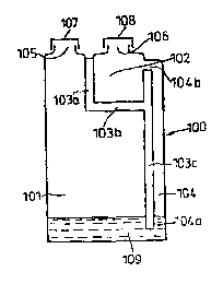
The sampling vessel 100 illustrated in Fig 1 is in the
form of a bottle comprising a major chamber 10. and a
minor chamber 102 forming the sample analysis region. The
minor chambex 102 is defined by internal walls 103a-c of
the vessel. As illustrated in the drawing, chamber 102
is at an upper region of the vessel 100 and is in
communication with chamber 101 via a flow path in the
form of a passageway 104 defined by interior wall 103c.
Passageway 104 extends between a. lower J.iquid transfer
port 104a (at a lower region of the mayor chamber I01)
and an upper liquid transfer port 104b (at an upper
region of the sample analysis chamber 102). Each of
chambers 107. and 102 has a respective upper aperture 105
and 106 provided with a removable cap 107 or 108.
Vessel 100 is formed of a pliable plastics material
permitting the transfer (by sa_ueezing of the vessel) of
liquid from main chamber 101 to sampling chamber 102 as
described mare fully below.
:'he vessel 100 may, far example, be of the type d.i.sclosed
in EP-R-0 010 365 (He.ttix).
3o Reference is now made to Fig ~ illustrating the support
component 200 which will bE seen to comprise a aEnerally
CA 02334928 2000-12-13
13-DEC-00 17:23 FROM:H6F LEEDS +44 113 230 4702 70:0016046875756 PACE:021~050
WO 99167632 PCT/G$99IQIS20
19
cylindrical body 201 with an outer diameter less than the
inner diameter of aperture 106. xhe body 201 may
altexnatively be of any suitable cross-sectional shape,
such as sc~sare, rectangular or hexagonal. Tn one
variation, as illustrated in Figure 2, at its lower end
the body 201 has a downwardly tapering conical tip 202
with an apical aperture 203. Othex possible constructions
are Shawn in Figure 5, of which those of Figures 5a and
5c are preferred. Towards its upper end, the body 201 is
pxovided with an external annular flange 204 with a
depending skirt 205. It will be appreciated from Fig 2
that the support component 200 is dimensioned to allow
the body 201 to be inserted through the opening 106 such
that the support component 200 is supported by virtue of
LS the flange 20~ resting on the J.ip of aperture :.06 and
with its tip below the level of part 104b but above the
base of charc~ber 102. ,
It will be seen from Fig 2 that the support component 200
(supported on the opening 106 as described? is able to
locate in position a sensor device 300 shown in more
detail in Fig 3 to which reference is now made. Sensor
device 300 comprises an enlarged head portion 301
connected to an elongate finger 302 which is partially
"cut-away" whereby the ~inger includes a shoulder 303 and
a longitudinally extending flat section 304. An
electrochemical sensor 305 (e. g. an enzyme based
amperorttetric sensor) is removably connectable through a
contact arrangement 306 located in the .shoulder :03. A
temperature sensor 307 is provided at the ~ree e:~d oT
finger 302 as shown. As illustrated in Fig 3a, t:ze f..ee
CA 02334928 2000-12-13
13-DEC-00 17:23 FROM:HCaF LEEDS +44 113 230 4702 T0:0016046B75756 PRCE:022~050
WO 99167632 PCTIGB9910a820
end of the finger 302 extends beyond the end of the
sensor 3Q5. This need not necessarily be so and as
illustrated in Fig 3b the finger 302 may be shorter than
the sensor 305, provided that the sensor is adequately
5 supported, Wires (not shown} for connecting the
electrochemical sensor 305 and temperature sensor 307 to
the necessary electronic measuring and control anpaxatus
axtsnd from the contacts 306 and temperature sensor 307
through the finger 303 and head 301.
to
As wzll be appreciated from Fig 2, the sensor device 300
. is such that it may be supported by means of its head 301
in the support component 200 so ,that the sensing area of
the liquid electrochemical sensor 305 is fully immersed
15 in the liquid.
xhe electrochemical sensor 305 may for example be an
enzyme based amperometric sensor capable of measuring the
concentration of alcohol (or other species of interest)
24 present in the liquid. The characteristics of such
alcohol sensors are such that a minimum dissolved oxygen
content is generally required in the liquid analyze
sample and measurements are adversely influenced by the
formation of gas bubbles on the sensor surface.
Alternatively the sensor 305 may be for determining a
differene analyze or may incorporate several sensor areas
on a single element for determining different analytes.
The manner in which the components trus far c.escribed
with reference to Figs 1-3 are used far af~ec~ing a
measurement or_ a liquid sample will now :oe descr-bed.
CA 02334928 2000-12-13
13-DEC-00 17:24 FROM:HGF LEEDS +44 113 230 4702 70:0016046875756 PRCaE:023~050
WO 99167632 PCT/GB9911fi82U
21
Tnitially, liquid 109 to be analysed (e. g,. an alcoholic
beverage such as beer or wine) is introduced =nto the
main chamber 101 of the sampling vessel. 100 to a level
which may be (but is wot necessarily) above the lower ,
liquid trarzsfer poxt 104a and the caps 107 and 14a are
located in position. The volume of liquid to be added
will be dependent on the type pf sample. For exarrrole, if
the chamber 107. has a volume of 500m1 then it would be
1Q appropriate to use 100m1 of wine. Alternatively, 25rn1 of
beer would be appropriate fox- a 500m1 chamber. In the
case of relaCively small volumes of liquid it is
alternatively possible to introduce the liquid firstly
into sample analysis chamber IOZ and then tilt the bottle
100 so that the liquid is transferred into chamber x01.
This procedure has the advantage (for small volumes of
liquid) in that the small chamber 102 may have a
gradation mark which more accuzately represents the
relatively small volume of liquid than would a gradation
mark (for the sample volume) on the chamber 1C1. In
anaeher variation, one of the closures 106,208 may be
used to measure an appropriate sample volume, or some
other specific container may be provided for this
purpose.
Vessel 104 is then shaken (e.g. 10-30 vigorous shakes or
thirty seconds continuous shaking .~riZl generally be
appropriate) which results in an exchange of gas between
the liquid and i.r.s surroundings with a two-fold efxe=t.
Firstly, carbon dioxide is released Exam the iiqsid
possibly genera~ing a froth 110 (see Fig 4). 5econd~y,
CA 02334928 2000-12-13
13-DEC-00 17:24 FROM:HC~F LEEDS +44 113 230 4702 70:0016046875756
PtaCE:024~050
WO 99167632 PCTIGB99I01$2Q
22
the dissolved ox~~gen content of the liquid is increased
thereby ~~conditivning~~ the liquid for measurement with
the sensor which (as mentioned above) may require a
minimum dissolved oxygen content. A mesh or baffles may _
S be disposed in the interior of the main chamber loI to
increase the efficacy of the shaking, In a variation of
the procedure, an anti-foam agent may be added to the
sample zn the main chamber 101 provided that the anti-
foam agent does not interfere with the analysis.
1a
Caps I07 and to a are then, removed ( in that order? prior
to cap 107 being replaced and tightened. This procedure
ensures that any excess gas~build-up within the vessel is
released without the liquzd entering the sample analysis
15 chamber 102, This pressure release step may additionally
be performed during a pause ~.n the shaking.
Alternatively, a pressure release valve may be provided
in the main (and minor) chambers. In another variation.,
the vessel may include at least one small hole at an
24 upper part cf the side walls for the release o~ excess
pressure.
After the pressure release, the main chamber 101 is
squeezed so that the sample liquid travels upwardly
25 through passageway 104 to fill the sample analysis
chamber 101. (In the case where the chamber 101 contains
a relatively low volume of liquid it may be necessary to
r.ilt the bottle to ensure that port 104a is covered) . A
valve or tap me be provided at port 104a .o prevent
30 transfer of the liquid sample into passageway 10t un~;.il
desired. The compression of ma;n charnbex 101 is then
CA 02334928 2000-12-13
13-DEC-00 17:24 FROM:HGF LEEDS +44 113 230 4702 70:0016046875756 PACE:025~050
W4 99/61632 ~'CTIGB991p1820
23
released permitting a volume of sample to remain in
chamber 3.02 (upto the level of paxt 104b with the vessel ,
100 vertical, or lower in some cases? wha.lst excsss is
sucked back into the main chamber 101. Since the liquid
level in main chamber 101 is often above port 104a, most
of the froth remains in main chamber 101 although a
portion may enter the sample analysis chamber L02.
bubble filter of bubble trap may be incorporated in. the
passageway 104 if desired, to reduce the possibility of
L0 transmission of foam into' the chamber 102. After this
point, the aperture 105 may be left open or closed.
zn the next stage of the procedure, support component 200
is insexted into chamber 102 so that its' conical tig 202
(or other leading end construction, such as those of ;
Figure 5) is below the level of the liquid 7.09 therein.
The shape of support component 200 ensures that it
"parts" the froth as it passes therethrough and as a
result the lower region cf body 20I and the tip 202
contain an "un-frothed" sample of liquid. Subsequently, ,
the sensor device 300 is insaxted into the support
component 200 so that the lower end of the sensor 305 is
immersed in the liquid 109_ The positioning of the
sensor device 300 in the support component 200 ensures a
predetermined immersion depth for the sensor 305. Since i
many sensors are susceptible to excess liquid causing
problems of corrosion, contamination ox electrical short
circuits, the use of the support componer~t 200 overcomes
these problems.
Although advantageous, the use of the supp4r~ component
CA 02334928 2000-12-13
13-DEC-00 17:24 FROM:HCaF LEEDS +44 113 230 4702 70:0016046875756 PA6E:026~950
WO 99167632 PCTIGB99101SZU
24
200 is not essential. Thus, the relative constxuctzons '
of the sensor device 300 and~the miner chamber I02 may be
such as to provide a predetexmiz~ed depth of irnmersioa cf
the sensor 305. Iz~ one possible variation, the sensor
may have a needle like construction and the closure 108
may be in the form of a rubber septum which is pierced by
the sensor. rn this construction, additional ventilation
of the minor chamber 102 may be required.
It should at this point be appreciated that there are
clearances between the outez surface of body 201 (of the
support component 200) and the inner surface of aperture
106 and also between the inner surface of body 201 and
the sensing head 300. These clearances avoid problems j
with "piston effects" and capillary filing of narrow
gaps. Such problems could otherwise arise if the
components are wet from rinsing or from a previous
measurement. In a modification; (riot illustrated) spacers
may be provided on the lower surface of flange 204 to
2o avoid a seal being formed with the annular rim defining
i
the aperture 106. Thus a clear air space continuous from
I
the atmosphere to the interior of chamber 102 and from
the atmosphere to the interior of the support component
200 is defined such that the clearances are not liable to
i 25 be filled by capillary action or stray droplets of .
liquid. In a further modification (not illustrated) the
clearances rnay be achieved by providing (additionally to
ox alternativeyy to the annular flange 204 and skirt 205?
the body 201 with circumferentially spaced,
i
30 longitudinally extending fins provided on the e3aerior
surface oz the body 201 whereby the suppo°t component 20C
CA 02334928 2000-12-13
'13-DEC'-00 17:25 FROM:HCaF LEEDS +44 113 230 4702 70:0016046875756
PRraE:027i~750
WO 49167632 ~CTlGS99/0182Q
is a push fit within the aperture 106. Furthermore, the
exterior surface of the cylindrical portion of the
elongate finger 302 (of the sensing arrangement 300y may
also be provided . with circumferentially spaced,
5 longitudinally extending fins whereby the cylindrical
portion 302 is a push fit in the support component 200.
A measurement may now be made of the alcohol (or other
analytey content of the beverage, It will be appreciated
10 from the forgoing description that the liquid z0~ in the
chamber 102 is of appropriate dissolved oxygen content to
permit the sensor 305 to function correctly. Moreover,
the liquid Z09 in the chamber 102 is of reduced carbon
dioxide content (as compared to the original liquid
15 sampley so that problems associated with bubble formation
on the sensor immersed in the liquid are minimised or
avoided completely. Furthermore, there is no
interference resulting from plunging the sensor thxough a
troth to the underlying liquid. r
In a mod~.fication of the above procedure, the support
component 200 may be inserted into, and supported by, the
aperture 106 prior to squeezing the bottle to introduce
the liquid into the sampling chambex 102. In furthex
modifications of the technique described, the lower end
j
of the support component 200 may have any of the
alternative configurations illustrated in Fig 5. All a~
these are characterised by the Feature that they yn~lude
one or more restricted openings pe~n.itting liquid to
enter the support component but pre~renti.ng the ingress of
froth. In the preferred constractions of Figures Sa and
CA 02334928 2000-12-13
13-DEC-00 17:25 FROM:HC~F LEEDS +44 113 230 4702 70:0016046875756
PAC~E:029~050
WO 99167632 PC'TIGIi991418Z0
26
5c, the leading (lower) end of the component 200 has a
generally p~.anar end c~,osure part z50 with an inlet tube
251. The inlet tube 251 communicates with the interior of
the component 200 by means of an orifice 252 in the end
closuxe part 250.
In order to facilitate cleaning of the vessel loo after
use, further apertures may be provided to allow a through
flow of cleanz.ng fluid (eg water).
Reference is now made to Figs 6 - 8 which illustrate a
further embodiment of the invention. Referring tc Fig 6,
there is illustrated a sampling vessel 400 having a
generally cylindrical body 402 provided in one end face
with an apertuxe 402 closed by a removable cap 403. At
its end opposite to opening 402, the body 402 is provided
with a V-shaped tubular arm 404 formed by limbs 405 and
405. Limb 405 communicates with the interior of body 401
and the end og limb 406 is provided with a removable cap ',
407.
for use in sample preparation, the vessel 400 ,is
positioned with opening 402 uppermost (as illustrated in
Fig 6) . With cap 40? zn position, liquid sample 408 is .
introduced into the vessel so as to enter and fill the V-
shaped tubular arm 404 such that there may also be liquid
in the base of body 401.. Vessel 400 is now shaken as
previously. Gas bubbles rise ~rom the tubular arrn 444
(Fig '7) so that any froth 409 is mostly within t:~e body
4~1 and onl~r ~~un--frothed" lia_ui3 remains in the distal
end of the Lobular arm 406. Care=u,~ rotation of vessel
CA 02334928 2000-12-13
13-DECr00 17:26 FROM:HCF LEEDS +44 113 230 4702 70:0016046875756 PACE:029~050
WO 99167632 PCTIG999101820
z~
400 sa that its longitudinal axis becomes horizontal {Fig
8) ensures that substantially all of the froth remains in
the (now horizontal) body 441 and a defined volume of
liquid is in the tubular arm 404. Cap 403 and then 407
may now be removed and a sensor inserted so as to effect
a measurement as previously described.
The depth of immersion of the sensor is controJ.~.ed by the
level df liquid in the arm 406. This may in turn be '
Controlled try ensuring that, with the body 101
horizontal, the level of the liquid is below the lip 410
{at the junction between the body 401 and the side arm
405). On opening cap 403 and then cap 4p7 the level of ,
the liquid iz~ the side arm 404 will drag to that defined
by lip 410.
The shape .and dimensions of the apparatus illustrated irx
Figs 6 - 8 are not critical and the v-shaped arm could be
replaced by a U-shaped arm or a complex series of
baffles. The key point is the separation of froth by a
partition - in the illustrated embodiment by the upper
side of the ~w~~ at the junct~.on of arms 405 and 406. ,
Referring now to Figures 9 and 10, in which there is
illustrated an alternative sample preparation vessel in
accordance with the seventh and eighth aspects of the ,
invention. This vessel may be used in combination with
the sensor device and sensax~ support component in the
same manner as for the other aspects of the invention,
anal these will not be described further.
CA 02334928 2000-12-13
13-DEC-00 17:26 FROM:HCF LEEDS +44 113 230 4702 70:0016046875756 .
PRCaE:030~050
WO 99167632 PCT/GB99/01820
28
The vessel 900 of Figures 9 and l0 comprises a single
chamber 901 which is divided by a baffle 902 into a main
region 903 and a sample analysis region 904. T'he baffle '
902 extends across the full width of the vessel 900 but
S its free end 905 is spaced apart from the base 906 of the
vessel 900. The baffle 902 depends from the tcp wall 907
of the vessel 900. The tap wall 907 includes and openable
and clv.seable aperture 911 in the sample analysis region
904 and an optional operable and closeable aperture in
IO the main region 903.
In use, the vessel 900 is filled with 7.zc~uid sample 909
until, with the vessel 900 in the orientation illustrated
in Figure 9, the baffle 902 is submerged. After filling
15 the sample preparation steps (which may be any of those
previously mentioned) may be carried out. The vessel 900
is closed at an appropriate point in these steps.
Preferably the preparation step is a shaking step for
degassing and/or oxygenating the sample, In this case,
20 a~ter the container is closed, it is shaken in the
orientation shown ~.n Figure 9. This shaking will normally
generate an undesirable foam 910, which oould interfere
with the accuracy of measurements taken with the sensor
(see below?. Thus, in order to ensure that there is no
2S foam 910, or a minimum of ~oam 910 in the sample analysis
region 909, the vessel 900 is carefully rotated through
about 90° in (in the example illustrated? a clockwise
direction, so 'that the vessel 900 adopts the orientation
shown in Figure 10 . Ir. this way, the baf fle 902 pre~rents
30 all, or the ~naaerity, of the foam 910 from passing into
the sample anslysis region 904.
CA 02334928 2000-12-13
13-DECr00 17:26 FROM:HCF LEEDS +44 113 230 4702 70:0016046875756 PA6E:031~050
WO 99167632 PCTIGB99/01820
29
The aperture 911 in the sample analysis region 904 may
then be opened and a sensor device including a sensor
inserted Chrough the aperture 911 so that the sensor
enters the liquid sample. A measurement of the species
to be determined may then be made with the sensor device. ,
It will be appreciated from the foregoing description
that the illustrated embodiments provide a~simple, quick
lb and inexpensive means of sample preparation and analysis.