Language selection

Search

Patent 2334968 Summary

Third-party information liability

Some of the information on this Web page has been provided by external sources. The Government of Canada is not responsible for the accuracy, reliability or currency of the information supplied by external sources. Users wishing to rely upon this information should consult directly with the source of the information. Content provided by external sources is not subject to official languages, privacy and accessibility requirements.

Claims and Abstract availability

Any discrepancies in the text and image of the Claims and Abstract are due to differing posting times. Text of the Claims and Abstract are posted:

  • At the time the application is open to public inspection;
  • At the time of issue of the patent (grant).
(12) Patent: (11) CA 2334968
(54) English Title: FLARED NOTCH RADIATOR ASSEMBLY AND ANTENNA
(54) French Title: ENSEMBLE ELEMENT RAYONNANT A FENTES ET ANTENNE
Status: Term Expired - Post Grant Beyond Limit
Bibliographic Data
(51) International Patent Classification (IPC):
  • H01Q 13/08 (2006.01)
  • H01Q 13/10 (2006.01)
(72) Inventors :
  • KLEBE, DOUGLAS O. (United States of America)
  • TSO, LAN (United States of America)
  • BILLE, JEFFREY M. (United States of America)
  • CRANDALL, GARY L. (United States of America)
  • WANG, ALLEN (United States of America)
(73) Owners :
  • RAYTHEON COMPANY
(71) Applicants :
  • RAYTHEON COMPANY (United States of America)
(74) Agent: MARKS & CLERK
(74) Associate agent:
(45) Issued: 2002-07-30
(86) PCT Filing Date: 2000-04-13
(87) Open to Public Inspection: 2000-10-26
Examination requested: 2000-12-11
Availability of licence: N/A
Dedicated to the Public: N/A
(25) Language of filing: English

Patent Cooperation Treaty (PCT): Yes
(86) PCT Filing Number: PCT/US2000/009970
(87) International Publication Number: US2000009970
(85) National Entry: 2000-12-11

(30) Application Priority Data:
Application No. Country/Territory Date
09/293,145 (United States of America) 1999-04-16

Abstracts

English Abstract


An improved injection molded radiator assembly (10) and antenna assembly can
be made using multiple such radiator assemblies. The radiator assembly
includes an injection molded radiator enclosure (50) that forms an RF
waveguide channel (51). A circuit/RF probe subassembly (40) is mated to the
radiator enclosure that houses a circulator assembly (42), input and output
connectors (45), and an RF probe (46). An environmental plug (60) is disposed
in the radiator enclosure to seal the RF waveguide channel from the external
environment.


French Abstract

L'invention concerne un ensemble élément rayonnant moulé par injection (10) perfectionné, ainsi qu'un ensemble antenne pouvant être fabriqué à l'aide de multiples ensembles éléments rayonnants de ce type. L'ensemble élément rayonnant comprend un boîtier d'élément rayonnant moulé par injection (50) formant un canal de guide d'ondes RF (51). Un sous-ensemble circuit/sonde RF (40) est connecté au boîtier de l'élément rayonnant renfermant un ensemble circulateur (42), des connecteurs d'entrée et de sortie (45), et une sonde RF (46). Une fiche d'ambiance (60) est placée dans le boîtier de l'élément rayonnant pour isoler le canal de guide d'ondes RF du milieu extérieur.

Claims

Note: Claims are shown in the official language in which they were submitted.

6
What is claimed is:
1. Antenna apparatus comprising:
a radiator enclosure having an RF waveguide channel;
a circuit subassembly mated to the radiator enclosure that comprises a
carrier,
a circulator assembly, input and output connectors, and an RF probe; and
an environmental plug disposed in the radiator enclosure to seal the RF
waveguide channel from the external environment.
2. The apparatus recited in Claim 1 wherein the radiator enclosure comprises a
flared notch radiator element.
3. The apparatus recited in Claim 1 wherein the radiator enclosure comprises a
conductively plated injection molded plastic radiator enclosure.
4. The apparatus recited in Claim 1 wherein the carrier comprises an aluminum
carrier.
5. The apparatus recited in Claim 1 wherein the carrier provides a thermal
path to
transfer the heat generated by the circulator assembly.
6. The apparatus recited in Claim 1 wherein the carrier comprises two holes
for
mounting coaxial input and output connectors.
7. The apparatus recited in Claim 1 wherein the carrier comprises a threaded
mounting hole for securing the circuit subassembly to an aperture plate.
8. The apparatus recited in Claim 1 wherein the radiator enclosure comprises
conductively plated infection molded thermoplastic material.
9. The apparatus recited in Claim 1 wherein the radiator enclosure has a tab
on

-7-
its end.
10. Antenna apparatus comprising:
a plurality of radiator assemblies disposed on an aperture plate, each of the
radiator assemblies comprising:
a radiator enclosure that comprises an RF waveguide channel;
a circuit subassembly mated to the radiator enclosure that comprises a
carrier, a carrier that secures a circulator assembly, input and output
connectors, and
an RF probe; and
an environmental plug disposed in the radiator enclosure to seal the RF
channel from the external environment.
11. The apparatus recited in Claim 10 wherein the radiator enclosure comprises
a
flared notch radiator element.
12. The apparatus recited in Claim 10 wherein the radiator enclosure comprises
a
conductively plated injection molded plastic radiator enclosure.
13. The apparatus recited in Claim 10 wherein the carrier comprises an
aluminum
carrier.
14. The apparatus recited in Claim 10 wherein the carrier provides a thermal
path
to transfer the heat generated by the circulator assembly.
15. The apparatus recited in Claim 10 wherein the carrier comprises two holes
for
mounting coaxial input and output connectors.
16. The apparatus recited in Claim 10 wherein the carrier comprises a threaded
mounting hole for securing the circuit subassembly to an aperture plate.
17. The apparatus recited in Claim 10 wherein the radiator enclosure comprises
conductively plated injection molded thermoplastic material.

-8-
18. The apparatus recited in Claim 10 wherein the radiator enclosure has a T-
shaped tab on its end, which interlocks to a neighboring radiator assembly.


Description

Note: Descriptions are shown in the official language in which they were submitted.


CA 02334968 2000-12-11
V4'O 00/64008 PCT/US00/09970
rLARED NOTCH RADIATOR ASSENIBLY AND ANTENNA
BACKGROUND
The present invention relates generally to antennas and antenna radiator
assemblies, and more particularly, to a conductively plated injection molded
plastic
radiator assembly and antenna assembly constructed using same.
Conventional flared notch radiator assemblies are machined from aluminum,
and are consequently, much heavier than plated plastic. These conventional
assemblies are made up of a two piece housing that varies in length. Multiple
lengths
and quantities are required for different aperture configurations. The
conventional
approach increases programming, and tooling fabrication costs as well as
logistics
support. It would be desirable to have a radiator assembly that reduces these
costs
and minimizes the number of components in the assembly.
The conventional two piece housing exposes an RF probe directly to the
environment and can entrap moisture, thereby increasing susceptibility to
contaminants and corrosion. It would be desirable to have a radiator assembly
that
protects the probe and inhibits moisture from entering the enclosure.
IS Therefore, it is an objective of the present invention to provide for an
improved conductively plated injection molded plastic radiator assembly that
overcomes limitations in conventional designs and permits the construction of
improved array antennas, and the like.

CA 02334968 2002-02-11
7
w
SUMMARY OF 'rHE INVENTION
The present invention provides for an improved conductively plated injection
molded plastic. radiator assembly.
In accordance with one aspect of the present invention there is provided an
antenna apparatus comprising:
a radiator enclosure having an RF waveguide channel;
a circuit subassembly mated to the radiator enclosure that comprises a
carrier,
a circulator assembly, input and output connectors, and an RF probe; and
an environmental plug disposed in the radiator enclosure to seal the RF
waveguide
channel from the external environment.
In accordance with another aspect of the present invention there is provided
an
antenna apparatus comprising:
a plurality of radiator assemblies disposed on an aperture plate, each of the
radiator assemblies comprising:
a radiator enclosure that comprises an RF waveguide channel;
a circuit subassembly mated to the radiator enclosure that comprises a
carrier, a carrier that secures a circulator assembly, input and output
connectors, and
an Rf probe; and
an environmental plug disposed in the radiator enclosure to seal the RF
channel from the external environment.
The radiator assembly is designed as a single unit, which reduces the
tolerance
stack-up associated with machined aluminum radiator strips, and permits
unlimited
aperture configuration. The design of the radiator assembly inhibits moisture
from
entering the enclosure. Unique features of this self contained radiator
assembly
include its light weight, moisture resistance and ease of assembly and
installation.
The radiator enclosure is preferably injected molded using a suitable
engineering thermoplastic material that is conductively plated using
electrolyses
plating technologies. 'this enclosure has pockets to reduce weight and provide
a
waveguide channel and an alignment fixture during final assembly. The
enclosure
has a tab which interlocks to a neighbouring radiator assembly upon
installation. This
feature assists in alignment during installation and improves the overall
rigidity of the
antenna aperture.

CA 02334968 2002-02-11
'? a
Prior to final radiator assembly, the environmental plug is inserted into an
RF
channel section of the radiator enclosure. 'The plug seals the RF channel from
the
exten~~al environment. The circuit subassembly is then inserted into the
radiator
enclosure and the assembly is secured to the aperture plate.
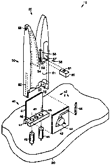
BRIEF DESCRIPTION OF THE DRAWINGS
The various features and advantages of the present invention may be more
readily understood with reference to the following detailed description taken
in
conjunction with the accompanying drawing figure, which is an exploded view of
an
exemplary radiator assembly in accordance with the principles of the present
invention.

CA 02334968 2000-12-11
WO 00/64008 PCT/US00/09970
3
DETAILED DESCRIPTION
Referring to the drawing figure, it is an exploded view of an exemplary
radiator assembly 10 in accordance with the principles of the present
invention. The
radiator assembly 10 is comprised of a flared notch radiator assembly 10
having a
flared notch radiator element 20. The flared notch radiator assembly 10 is a
conductively-plated injection-molded plastic radiator assembly 10. Multiples
of the
radiator assembly 10 mount to an aperture plate 30 of an antenna, shown
schematically as a flat plate. The radiator assembly 10 comprises three parts,
including a circuit/RF probe subassembly 40, a radiator enclosure 50, and an
environmental plug 60.
The circuit/RF probe subassembly 40 includes an aluminum carrier 41 onto
which a circulator assembly 42 comprising an alumina substrate 43 attached
thereto
that has a circulator 44, two coaxial input/output connectors 45, and an RF
probe 46
mounted thereto. The aluminum carrier 41 is T-scraped and provides rigidity
for the
entire circuit/RF probe subassembly 40 as well as a thermal path to transfer
the heat
generated by the circulator assembly 42 to the aperture plate 30. The carrier
41 also
has two holes 46 for the coaxial input/output connectors 45 and a threaded
mounting
hole 47 for securing it to the aperture plate 30. The alumina substrate 43 has
a
plurality of circuits 48 formed thereon that are used to couple energy through
the
radiator assembly 10.
The radiator enclosure 50 is preferably injected molded using a suitable
engineering thermoplastic material that is conductively plated using
electroless
plating processes. The radiator enclosure 50 has a pocket 51 which provides a
waveguide channel 51 for the RF probe 46, and slots 5? along sides of the
enclosure
50 which act as an alignment fixture during final assembly. Two tabs 59 are
provided
at ends of the slots 52 that hold the circuit/RF probe subassembly 40 in place
when
the radiator assembly 10 is assembled. The enclosure 50 has a T-shaped tab 53
on an
end of one of the flare points which interlocks to a neighboring radiator
assembly 10
upon installation. The T-shaped tab 53 assists in alignment during
installation and
improves the overall rigidity of the antenna aperture.
In the exemplary embodiment shown in the drawing figure, the waveguide
channel 51 has a rectangular cross section at the bottom of the enclosure 50
where the
circuit/RF probe subassembly 40 is inserted. The waveguide channel 51 extends
into

CA 02334968 2000-12-11
WO 00/64008 PCT/US00/09970
4
the left flared portion of the enclosure 50. The enclosure 50 has an internal
wall 54
extending laterally across a portion of the interior of the enclosure 50. The
internal
wall 54 has an opening 55 through which the probe 46 is inserted, and a cavity
56 in
the right flared portion of the enclosure 50 that holds the probe 46. The
environmental Piug 60 is inserted in an opening between the internal wall 54
and the
portion of the enclosure where the cavity 56 is located. An L-shaped cavity 57
is
formed in the right flared portion of the enclosure 50 above the internal wall
54.
The circuitlRF probe subassembly 40 is assembled and electrically tested prior
to insertion into the radiator enclosure 50. The environmental plug 60, or
gasket 60,
is disposed in the radiator enclosure 50 and is self-sealing prior to the
circuit
subassembly 40 is inserted into the radiator enclosure 50 during final
assembly. The
environmental plug 60 has an opening 61 therein that aligns with the opening
55 in
the internal wall 54 of the enclosure 50 and with the cavity 55, into which
the probe
46 is inserted.
The environmental plug 60 is preferably a molded, moisture resistant, low loss
dielectric plug 60. Prior to final assembly of the radiator assembly 10, the
plug 60 is
inserted into an RF channel section 58 of the radiator enclosure 50 and the
opening 61
therein is aligned with the opening 55 in the internal wall 54 of the
enclosure 50 and
with the cavity 55. The plug 60 seals the RF channel 51 from the external
environment. The circuit/RF probe subassembly 40 is then inserted into the
radiator
enclosure 50 with the probe 46 inserted through the opening 55 in the internal
wall 54
of the enclosure 50, the opening 61 in the plug 60 and into the cavity 56. The
assembled circuit/RF probe subassembly 40 is secured by sliding the aluminum
carrier 4i along with the substrate 43, probe 46 and input/output connectors
45 into
the waveguide section 51 using the slots 52 as guides, and until the
circuit/RF probe
subassembly 40 is secured by the tabs 59 within the waveguide channel 51. The
radiator assembly 10 is secured to the aperture plate 30.
The radiator assembly 10 is designed as a single unit. The radiator assembly
10 reduces the tolerance stack up associated with machined aluminum radiator
strips
used in conventional devices and permits unlimited aperture configurations.
The
design of the radiator assembly 10 protects the RF probe 16 and inhibits
moisture
from entering the enclosure 50. Unique features of the self-contained radiator

CA 02334968 2000-12-11
V~.JO 00/64U08 PCT/US00/09970
assembly 10 include its light weight, moisture resistance and ease of assembly
and
installation.
The present invention may be used with any active array antenna system using
flared notch radiators. The present invention is intended to lower the cost,
improve
5 the versatility, and improve the performance of antenna systems in which it
is
employed.
Thus, an improved radiator assembly has been disclosed. It is to be
understood that the described embodiment is merely illustrative of some of the
many
specific embodiments that represent applications of the principles of the
present
invention. Clearly, numerous and other arrangements can be readily devised by
those
skilled in the art without departing from the scope of the invention.

Representative Drawing
A single figure which represents the drawing illustrating the invention.
Administrative Status

2024-08-01:As part of the Next Generation Patents (NGP) transition, the Canadian Patents Database (CPD) now contains a more detailed Event History, which replicates the Event Log of our new back-office solution.

Please note that "Inactive:" events refers to events no longer in use in our new back-office solution.

For a clearer understanding of the status of the application/patent presented on this page, the site Disclaimer , as well as the definitions for Patent , Event History , Maintenance Fee  and Payment History  should be consulted.

Event History

Description Date
Inactive: COVID 19 - Reset Expiry Date of Patent to Original Date 2020-06-16
Inactive: COVID 19 - Deadline extended 2020-06-10
Inactive: COVID 19 - Deadline extended 2020-05-28
Inactive: COVID 19 - Deadline extended 2020-05-14
Inactive: COVID 19 - Deadline extended 2020-04-28
Inactive: Expired (new Act pat) 2020-04-13
Inactive: COVID 19 - Deadline extended 2020-03-29
Common Representative Appointed 2019-10-30
Inactive: IPC from MCD 2006-03-12
Grant by Issuance 2002-07-30
Inactive: Cover page published 2002-07-29
Pre-grant 2002-05-21
Inactive: Final fee received 2002-05-21
Notice of Allowance is Issued 2002-03-28
Letter Sent 2002-03-28
Notice of Allowance is Issued 2002-03-28
Inactive: Approved for allowance (AFA) 2002-03-14
Amendment Received - Voluntary Amendment 2002-02-11
Letter Sent 2001-12-03
Inactive: Correspondence - Transfer 2001-11-06
Inactive: Correspondence - Formalities 2001-11-06
Inactive: Courtesy letter - Evidence 2001-10-22
Inactive: S.30(2) Rules - Examiner requisition 2001-10-17
Amendment Received - Voluntary Amendment 2001-08-10
Inactive: Correspondence - Transfer 2001-08-10
Inactive: Correspondence - Formalities 2001-08-10
Inactive: Cover page published 2001-04-06
Inactive: First IPC assigned 2001-03-27
Inactive: Courtesy letter - Evidence 2001-03-20
Inactive: Acknowledgment of national entry - RFE 2001-03-16
Application Received - PCT 2001-03-09
All Requirements for Examination Determined Compliant 2000-12-11
Request for Examination Requirements Determined Compliant 2000-12-11
Application Published (Open to Public Inspection) 2000-10-26

Abandonment History

There is no abandonment history.

Maintenance Fee

The last payment was received on 2002-03-27

Note : If the full payment has not been received on or before the date indicated, a further fee may be required which may be one of the following

  • the reinstatement fee;
  • the late payment fee; or
  • additional fee to reverse deemed expiry.

Patent fees are adjusted on the 1st of January every year. The amounts above are the current amounts if received by December 31 of the current year.
Please refer to the CIPO Patent Fees web page to see all current fee amounts.

Owners on Record

Note: Records showing the ownership history in alphabetical order.

Current Owners on Record
RAYTHEON COMPANY
Past Owners on Record
ALLEN WANG
DOUGLAS O. KLEBE
GARY L. CRANDALL
JEFFREY M. BILLE
LAN TSO
Past Owners that do not appear in the "Owners on Record" listing will appear in other documentation within the application.
Documents

To view selected files, please enter reCAPTCHA code :


To view images, click a link in the Document Description column. To download the documents, select one or more checkboxes in the first column and then click the "Download Selected in PDF format (Zip Archive)" or the "Download Selected as Single PDF" button.

List of published and non-published patent-specific documents on the CPD .

If you have any difficulty accessing content, you can call the Client Service Centre at 1-866-997-1936 or send them an e-mail at CIPO Client Service Centre.


Document
Description 
Date
(yyyy-mm-dd) 
Number of pages   Size of Image (KB) 
Abstract 2000-12-10 1 50
Drawings 2000-12-10 1 19
Claims 2000-12-10 3 64
Description 2000-12-10 5 194
Description 2002-02-10 6 216
Claims 2002-02-10 3 68
Representative drawing 2001-04-05 1 8
Notice of National Entry 2001-03-15 1 203
Reminder of maintenance fee due 2001-12-16 1 112
Courtesy - Certificate of registration (related document(s)) 2001-12-02 1 113
Commissioner's Notice - Application Found Allowable 2002-03-27 1 166
Correspondence 2001-03-15 1 21
PCT 2000-12-10 4 158
Correspondence 2001-10-21 1 24
Correspondence 2001-11-05 2 78
Correspondence 2002-05-20 1 49
Correspondence 2001-08-09 2 80