Note: Descriptions are shown in the official language in which they were submitted.
CA 02335407 2003-11-18
Description:
Technical Field:
This invention relates to a rotary vane engine with two vanes and two
eccentric
rotors. This engine is designed for use in any application that currently
available
internal combustion engines are now being used in.
Background of the Invention:
Typically, existing rotary engines are of 3 different types: a rotary engine
with
vane(s), a rotary engine with toothed gears or the like, and a rotary engine
with
oscillating motion. Rotary engines having vanes) have many variations, one of
which is a rotary vane engine with an eccentric rotor, to which this invention
ascribes to.
The main structural features of such an engine are as follows: the cylinder is
of
cylindrical shape; a shaft is provided at the axis passing the centre of the
cylinder; a vane rotating around the axis is disposed radially between the
axis
and the internal wall of the cylinder; a hollow cylindrical rotor with a
longitudinal
slot is located eccentrically in the cylinder around said centre shaft, and
the
external wall of the rotor is tangential to the internal wall of the cylinder;
a
combustion chamber, the volume of which changes with the rotation of the
rotor,
is formed between the external wall of the rotor and the internal wall of the
cylinder so as to execute the working cycle of the internal combustion engine.
Such an engine may have a vane or a plurality of vanes, as disclosed in, eg.,
U.S. Pat. Nos. 3,132, 632, 2,969,049 and 3,289,653.
Up to now the rotary engine has not been widely used in practice because it
has
serious deficiencies and cannot measure up to the requirements for simple,
reliable and highly efficient work. In respect to U.S. Pat. No. 3,132,632, the
angles between the said vanes are inconsistent during operation, so that these
vanes cannot be all fixed on the centre shaft. Power output is achieved
through
Page 2 of 22
CA 02335407 2003-11-18
the function of the vanes that move the eccentric rotor. Because of the great
stresses endured between the vanes and the slots from which the vanes project
during combustive explosions, the slide or sealing member wears out quickly
causing the whole engine to fail.
For such an engine with a single vane, as described in U.S. Pat. Nos.
2,969,049
and 3,289,653, although the power output mode in which the vane is fixed with
the centre shaft is used, there exist some obvious deficiencies. First, it is
necessary for the engine of U.S. Pat. No 2,969,049 to provide a set of special
mechanisms to drive the eccentric rotor and the vane to execute the working
cycle. Therefore, the eccentric rotor rotates on the internal wall of the
cylinder by
the action of the drive means, complicating the structure and being difficult
to
achieve a good seal and adequate lubrication. Moreover, during operation,
attrition is produced between the vane and the rotor, thus causing the sealing
member to wear out, and resulting in complete engine failure.
Other models of rotary engines such as those disclosed in U.S. Patent numbers
5,352,295, 2,969,049, 3,132632 and 3,289,653 are more complicated, having
many more moving parts which makes them less efficient, because power is
transferred indirectly to the drive shaft through a sequence of various
internal
geared parts or oscillating mechanisms before it finally reaches the drive
shaft.
The Boucher Rotary Engine transfers power directly to the drive shaft. Because
of the simplicity of its design, there are less things to go wrong and less
chance
of parts breaking or jamming up.
The Boucher rotary engine may have as little as only 6 moving parts and the
force of combustion is applied in the direction that the shaft normally
rotates in,
unlike a conventional piston driven engine where the force of combustion
causes
the piston to come to a dead stop at the bottom of its stroke.
Page 3 of 22
CA 02335407 2003-11-18
The Boucher Rotary Vane Engine turns in the direction of the stroke, never
coming to a stop, but continuing a smooth rotation. This means less wasted
energy and therefore more useable energy available for torque.
The engine fires once per rotation cycle at the same place every time, making
the engine timing much easier to synchronistically accomplish.
Summary of the Invention:
An object of this invention is to provide a rotary vane engine simple in
structure,
with fewer moving parts, and more reliable in operation.
Another object of this invention is to provide a rotary engine with maximum
energy utilization and minimal energy loss.
Another object of this invention is to provide a rotary vane engine in which
cooling and lubrication can be easily accomplished.
The technical solution of this invention is to introduce a more efficient
concept in
the basic construction of rotary engines, that being to make the vane
independent of the rotor and drive shaft by placing it in a recess in the
housing,
rather than on the rotor or drive shaft, and to have the vane reciprocate on a
radial axis rather than linearly.
This technical solution greatly reduces the surface areas being subjected to
friction and permits the rotor to turn easier, with the result of improved
efficiency
and reduced energy loss.
Brief Description of Drawings:
Figure 1 illustrates the various phases of the engine during a working cycle.
Figure 2 is a view of the front plate that closes off the front of the engine
housing.
Page 4 of 22
CA 02335407 2003-11-18
Figure 3 is a view of the compression rotor and compression vane in the
housing.
This is the view you would see if the front plate were removed.
Figure 4 is a view of the mid plate that separates the compression portion of
the
engine from the expansion portion.
Figure 5 is a view of the expansion rotor and expansion vane in the housing.
This
is the view you would see if a section were taken through the engine just
after the
mid plate.
Figure 6 is a view of the back plate that closes off the back of the engine
housing.
Figure 7 is a cutaway view through the side of the engine, showing the
compression rotor and vane, the expansion rotor and vane, the front , mid and
back plates and the housing of the engine when it is properly assembled.
Description of the embodiment:
The main structural features of the engine are as follows:
There are 2 eccentric rotors 42 & 43, mounted on a shaft 46, the centre of
which
is the axis the shaft and rotors turn on. One rotor is called the
'compression' rotor
43 and the other is called the 'expansion' rotor 42. When viewed from their
ends
both rotors resemble a 3/ moon shape, but have an eccentric cylindrical shape
laterally. They are fixed to the shaft 180 degrees from each other, so their
respective weights are centrifugally counterbalanced when the engine is
turning,
thus reducing vibration.
From front to back the engine block features a front plate 12, the compression
housing 13, a mid plate 11, the expansion housing 21 and a back plate 40. The
compression housing 13 and the expansion housing 21 feature an inner cavity
that is cylindrical in shape to accommodate the rotors. The front plate 12 and
the
back plate 40 feature counterbored holes 51, centred relative to the inner
cavity,
that are fitted with bearings 50, which hold the drive shaft 46 in place at
both
ends of the engine.
Page 5 of 22
CA 02335407 2003-11-18
The drive shaft 46 also passes through the mid plate 11 with a rotor mounted
on
the drive shaft 46 on either side of the mid plate 11. Bolts are inserted in
holes
41, which extend through the entire length of the housing, parallel to the
drive
shaft 46. These, together with bolts inserted in holes 39, which thread into
the
mid plate, hold the whole assembly together.
The mid plate 11 separates the compression portion of the engine from the
expansion portion. The compression portion and expansion portion of the engine
each contain a rotor and vane arrangement. The concentric portion of the
external working surface 25 of each rotor is fitted to the internal surface of
the
housings 13 and 21 with just enough minimal clearance to permit rotation.
The eccentric portion of the working surface 24 of each rotor is designed to
create a crescent shaped chamber between itself and the cylindrical inner
surface of the housing. The chamber rotates with the rotor as the drive shaft
46 is
turned.
The housings 13 and 21 also contain a moveable vane for each rotor, which
retracts into the housing in an arc movement by pivoting on a pin 28. Each
vane
is spring loaded with a vane spring wound radially around the pivot pin of the
vane with one end 36 biased toward the housing and the other end 35 hooked
through a hole in the side of the vane to cause the vane to lift and press
against
the rotor. A strip of wear resistant material that is called a glide 55, is
attached to
an external strip on the edge of the vane called the head 56 to maintain a
tight
seal against the working surface of the rotor, the pressure being dependant on
the force of the spring 1. In this way the vane and its glide 55 resting
against the
rotor form a seal to prevent gasses within the compression or expansion
chamber from circumventing them.
At a specific area on the compression side of the engine block, there is an
air
intake port 15 that permits ambient air to enter the compression chamber.
Page 6 of 22
CA 02335407 2003-11-18
Similarly, at a specific area on the expansion side of the engine block, there
is an
exhaust port 22, which permits exhaust gases to be expelled to an exhaust
system or to the atmosphere.
A tiny opening called the air transfer hole 7 in the mid plate is provided to
allow
the compressed air to transfer from the compression chamber 20 to the
expansion chamber 3. A spark plug 59 is fitted on the expansion portion of the
engine, along with a fuel injector 54 that, at a certain point in the engine's
rotation, come into contact with the expansion chamber. The spark plug 59 and
the fuel injector 54 may be located at the bottom of the engine, as shown in
Figure 5, or they may be located on the back plate 40 for easier access. These
are the major parts of the engine.
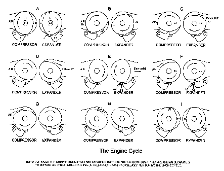
Figure 1 - The Engine Cycle
The working cycle of the engine is best understood by the various stages shown
in Figure 1. Although the compression rotor 43 and expansion rotor 42 are
mounted on the same shaft, they are shown independently in Figure 1 to
facilitate a better understanding of their relationship to each other during
the nine
illustrated stages of an engine cycle. Both rotors are turning clockwise.
Beginning at Stage E, as the shaft turns, the compression chamber is fully
exposed to the atmosphere, filling with ambient air as it rotates past the
intake
port, shown to the left, through Stages F, G and H. The compression rotor
surface gets increasingly closer to contacting the inside surface of the
housing at
the intake port, until it effectively closes off the intake port from the
compression
chamber at Stage I. At Stage I, the compression Rotor has blocked off the
intake
port completely at the point marked 'W'.
Going now to Stage A, Vane 18 comes into play. The shaft continues to turn and
the rotating compression chamber begins to decrease in volume as the rotor
Page 7 of 22
CA 02335407 2003-11-18
forces it against compression vane 18. Because the charge is unable to
circumvent the vane, it becomes compressed as the chamber volume reduces
throughout Stages B, C, D and E during rotation.
A small opening 7 in the mid plate 11, just ahead of the compression vane 18,
provides the only means of escape for the compressed charge. At Stage E, the
compression rotor 43 has now completed its compression of the charge, which
has been forced through the opening into the expansion chamber 3 on the
expansion side of the mid plate 11.
At this point the expansion chamber 3 is at its smallest volume, existing that
way
as a result of the relationship between the expansion rotor 42, expansion vane
30 (identified in the Stage A view) and the cylindrical inside surface of the
housing.
At the expansion rotor 42, the spark plug 59 and fuel injector 54 are shown.
At
this point, the fuel injector 54 sprays atomized fuel into the expansion
chamber,
which mixes with the compressed air.
At Stage F, with the Compression Rotor now in a position to prevent any
expansion from occurring on the compression side of the engine, the spark plug
59 fires.
The fuel mixture is ignited causing an explosion in the expansion chamber. As
the explosion occurs, the expansion chamber 3 has to become larger to
accommodate the increase in the volume of the exploding charge.
Because the expanding gases are unable to circumvent expansion vane 30, the
impact of the explosion forces the expansion rotor 42 to turn. The expansion
rotor 42 turning under the pressure of the explosion, becomes the driving
force
that rotates the engine shaft as the expansion chamber 3 becomes larger
Page 8 of 22
CA 02335407 2003-11-18
throughout Stages G, H, I, then back to A. During the rotation, it comes into
contact with the exhaust port 22 during Stage B at point S. At Stage C the
exhaust gases are released into the atmosphere, or an exhaust system. A
second exhaust port 23 exists in the portion of the expansion rotor housing 21
which accommodates the expansion vane 30. This is shown in Figure 5 and
Figure 7.
Simultaneously, at the compression rotor 43, the compression chamber 20 is
now picking up a new charge of air from the air intake port 15 for the cycle
to be
repeated. Thus the engine continues to repeat its cycle over and over again.
The momentum and centrifugal force of the rotors turning is more than enough
to
keep the cycle repeating itself with a surplus of energy in the form of
torque,
making it possible for the engine to be useful to drive a machine or vehicle.
Figure 2 - The Front Plate
The front plate 12 may be made of any ferrous or non-ferrous metal, and
features
a circular array of cooling holes 52 that alternate with bolt holes 39 or 41
provided to allow the engine parts to be bolted together. Bolt holes 41
require
long bolts to pass through the entire length of the engine whereas bolt holes
39
require shorter bolts, which thread into tapped holes in the mid plate 11.
Another set of cooling holes 44, also arranged in a circular array, permit air
to
flow through the rotors in an intermittent pulse-like manner as the rotor
cooling
holes 52 align with them during rotation.
At the centre, there is a counter-bored hole 51 designed to hold a bearing 50
through which the drive shaft 46 will pass.
Page 9 of 22
CA 02335407 2003-11-18
The front plate is also equipped with alignment pins 47 so that when the
engine
is assembled, it fits together precisely.
The hole 10 may be fitted with a small bearing or oil bushing and is used to
support one end of the vane pivot pin 28 that the compression vane 18 pivots
on
shown in Figure 3.
Figure 3 - The Compression Rotor
Shown here is the compression rotor 43 and its vane 18 in place within the
compression rotor housing13. The compression rotor 43 is held in place on the
larger diameter portion of the drive shaft 45 by means of splines 2. This is a
tight
press-fit arrangement. The larger diameter 45 of the drive shaft contains the
splines 2 and they are present through the entire length of the compression
rotor.
The smaller diameter of the drive shaft 46 is sized to fit the bearing 50 on
the
front plate 12 shown in Figure 2. A recessed rotor end seal groove 8 is
positioned
around the perimeter of the rotor end plates 6 to accommodate an end seal 4
made of wear resistant material and is centred within the longitudinal rotor
wall 5.
Counter weights 31 are situated within the hollow rotor to maintain
centrifugal
balance. The rotor end plates 6 are identical on each end of the rotor and
contain
cooling holes 44. The compression rotor housing 13 contains cooling holes 52,
which alternate with the bolt holes 41. Bolt holes 39 require shorter bolts,
which
thread into the mid plate 11. They do not continue through the entire length
of the
engine because the placement of the vanes would obstruct them.
Louvres 19 are located within the housing 13 to direct air within the intake
port
15. A shoe made of wear resistant material called a glide 55 is located on the
edge of the vane 18 at the portion of the vane called the pivot head 56 and
the
Page 10 of 22
CA 02335407 2003-11-18
glide contact surface 29 makes contact with the working surface 24/25 of the
compression rotor 43.
The compression vane 18 also has a vane head seal 60 made of wear resistant
material, which sits in a recessed groove 58 on each side of the vane. The
vane
moves on a pivot pin 28, held in place by holes 10 in the front plate 12 shown
in
Figure 2 and the mid plate 11 shown in Figure 4.
The compression vane 18 has a tension spring 1 wound radially around pivot pin
28 inside the vane 18, that forces it in the direction of the rotor, so that
contact is
always maintained between the glide surface 29 and the working surfaces 24/25
of the compression rotor 43.
As the eccentric rotor rotates, it causes the compression vane 18 to move in
and
out of a pocket 57 in the compression rotor housing 13. Another seal 32 made
of
wear resistant material and seated within a groove 17 in the housing prevent
compressed air from escaping past the vane.
Bolt holes 33 are provided in the housing as a convenience to fasten an intake
manifold (not part of this invention) to the intake port. Holes are provided
for the
alignment pins 47 to maintain proper alignment between the housing 13 and the
front plate 12.
An oil pan 37 is bolted to the bottom of the engine that is filled to a
certain level
49 with oil. The oil pan features an oil filter 38 and an oil supply line 27
that is
equipped with a check valve 48. Oil is drawn up by a suction created by the
movement of the vane 18, so that a small quantity of oil 34 remains in the
vane
pocket 57 to lubricate the vane.
The check valve 48 keeps the oil from receding back into the oil pan. If too
much
oil accumulates in this area an overflow hole 26 returns it to the oil pan.
Page 11 of 22
CA 02335407 2003-11-18
A small indent 61 in the housing, lines up with the opening 7 on the mid plate
11
to assist in facilitating the transfer of compressed air from the compression
chamber 20 to the expansion chamber 3 in Figure 5.
Several small spring-like devices called laces 16 are fitted into cylindrical
slots in
the housing. They are thin sheets of spring material and apply moderate
pressure to the working surface of the rotor to help spread an even coat of
oil
across the working surface of the rotor and also prevent 'blow-by', a
condition
wherein compressed gases may have a propensity to slip through the clearance
gap between the rotor and the housing.
Figure 4 - The Mid Plate
The mid plate 11 is shown with the compression side facing out. The larger
hole
9 in the centre of the plate is the drive shaft clearance hole. Hole 10 shawn
on
the compression side of the mid plate 11 is not a through hole and is used to
support one end of the pivot pin 28 for the compression vane 18. Hole 14, also
not a through hole, is likewise used to support one end of the pivot pin 28
for the
expansion vane 30 and occurs on the opposite side of the mid plate.
The oddly shaped opening 7 is actually tapered and as it passes through the
mid
plate and becomes larger on the opposite side. This is the opening through
which
the compressed air is transferred from the compression chamber on one side of
the mid plate to the expansion chamber on the other side.
This opening may be an irregular shape as shown, or it could simply be a round
hole. The holes shown as 44 are through holes for cooling purposes as are the
holes shown as 52 which alternate with the bolt holes 41, much the same as on
the front plate 12 shown in Figure 2 and the back plate 40 shown in Figure 6.
Page 12 of 22
CA 02335407 2003-11-18
Figure 5 - The Expansion Rotor
Shown here is a section through the engine just past the mid plate on the
expansion side, showing the expansion rotor 42 and its vane 30 in place as
they
relate to the expansion rotor housing 21.
In the same way as on the compression rotor 43, the expansion rotor 42 is held
in place on the larger diameter portion of the drive shaft 45 by means of
splines
53.
The smaller diameter of the drive shaft 46 is sized to fit the bearing 50 on
the
back plate 40 shown in Figure 6. A recessed rotor end seal groove 8 is
positioned around the perimeter of the rotor end plates 6 to accommodate an
end
seal 4 made of wear resistant material and is centred within the longitudinal
rotor
wall 5.
Counter weights 31 are situated within the hollow rotor to maintain
centrifugal
balance. The rotor end plates 6 are identical on each end of the rotor and
contain
cooling holes 44. The expansion rotor housing 21 contains cooling holes 52
where the housing is solid 21, and cooling pipes 62 rather than cooling holes
where the exhaust port 22 is present. Both 52 and 62 alternate radially with
the
bolt holes 41.
The cooling pipes 62 extend through the length of the expansion housing 21 and
link cooling holes 52 in the mid plate 11 with the cooling holes 52 in the
back
plate 40. The cooling pipes allow the flow of cool air to continue through the
engine while simultaneously preventing the exhaust gasses from mixing with the
cooling air.
A shoe made of wear resistant material called a glide 55 is located on the
edge
of the vane 30 at the portion of the vane called the pivot head 56 and the
glide
Page 13 of 22
CA 02335407 2003-11-18
contact surface 29 makes contact with the working surfaces 24/25 of the
expansion rotor 42.
The expansion vane 30 also has a seal 60 made of wear-resistant material,
seated within a recessed groove 58 on each side of the vane. The vane moves
on a pivot pin 28, held in place by holes 14 in the back plate 40 shown in
Figure
6 and the mid plate 11 shown in Figure 4.
The expansion vane 30 has a tension spring 1 wound radially around pivot pin
28
inside the vane 30 that forces it in the direction of the rotor, so that
contact is
always maintained between the glide surface 29 and the working surface 24/25
of the expansion rotor 42.
As the eccentric rotor rotates, it causes the expansion vane 30 to move in and
out of a pocket 57 in the expansion rotor housing 21. Another seal 32 made of
wear resistant material seated within a recessed groove 17 in the housing
prevents compressed air from escaping past the vane.
Holes are provided for the alignment pins 47 to maintain proper alignment
between the housing 21 and the back plate 40.
Located in the oil pan 37 is an oil filter 38 and another oil supply fine 27
that is
also equipped with a check valve 48. Oil is drawn up by a suction created by
the
movement of the vane 30, so that a small quantity of oil 34 remains in the
expansion vane pocket 57 to lubricate the vane. If too much oil accumulates in
this area an overflow hole 26 returns it to the oil pan.
Opening 7 on the mid plate 11 is continued in the housing as part of the
expansion chamber 3. The firing pin of spark plug 59 enters the opening, as
does
the fuel injector 54, to provide the elements needed for combustion to take
place.
Laces 16 are fitted into cylindrical slots in the expansion housing 21 as
well.
Page 14 of 22
CA 02335407 2003-11-18
Figure 6 - The Back Plate
The back plate 40 may be made of any ferrous or non-ferrous metal, and
features a circular array of cooling holes 52 that alternate with bolt holes
39 or 41
provided to allow the engine parts to be bolted together. Bolt holes 41
require
long bolts to pass through the entire length of the engine whereas bolt holes
39
require shorter bolts, which thread into tapped holes in the mid plate 11.
When a propeller is attached to the drive shaft, it can induce air to flow
through
these cooling holes which are continuous throughout the other parts of the
engine housing to allow air flow to travel through the entire length of the
engine.
Another set of cooling holes 44, also arranged in a circular array, permit air
to
flow through the back plate as the engine is operating.
At the centre, there is a counter-bored hole designed to hold a bearing 50
through which the larger diameter portion of the drive shaft 45 will pass.
The back plate is also equipped with alignment pins 47 so that when the engine
is assembled, it fits together more precisely.
The hole 14 is used to support one end of the expansion vane pivot pin 28.
Figure 7 - The Cutaway View
The cutaway view reveals the inner parts of the engine previously described,
as
they would appear when the engine is assembled, but with portions of the
housing, front plate, mid plate, back plate and housing cutaway to reveal the
workings of the engine. The oil pan and the parts within it were removed for
better clarity. The cutaway view also illustrates a case wherein the radial
sizes of
Page 15 of 22
CA 02335407 2003-11-18
the compression portion of the engine are not identical to the radial sizes of
the
expansion portion. In this case, the shorter bolts 39 were used in place of
the
longer bolts 41. In a case such as this, one or both of the rotors would
contain a
counterweight to balance them during rotation. This is necessary to reduce
engine vibration.
The Item List
1. Vane Spring
2. Compression Rotor Splines
3. The Expansion Chamber
4. Rotor End Seal
5. Rotor Longitudinal Wall
6. Rotor End Plate
7. Mid Plate Air Transfer Hole
8. Rotor End Seal Groove
9. Drive shaft opening in mid plate
10. Recessed hole for compression vane pivot pin
11. Mid Plate
12. Front Plate
13. Compression Rotor Housing
14. Recessed hole for expansion vane pivot pin
15. Air Intake Port
16. Lace
17. Front Vane Seal Groove
18. Compression Vane
19. Stationary Louvre
20. Compression Chamber
21. Expansion Rotor Housing
22. Exhaust Port
23. Exhaust Vent Through Vane Housing
Page 16 of 22
CA 02335407 2003-11-18
24. Eccentric Portion of Rotor Working Surface
25. Concentric Portion of Rotor Working Surface
26. Oil Return From Vane
27. Oil Supply Line
28. Vane Pivot Pin
29. Contact Surface of Glide
30. Expansion Vane
31. Rotor Counter Weight
32. Vane Front Seal
33. Intake Manifold Bolt Holes
34. Oil Level in Vane Pocket
35. Vane Spring Moveable End
36. Vane Spring Stationary End
37. Oil Pan
38. Oil Filter
39. Engine Assembly Half Length Bolt Hole
4D. Back Plate
41. Engine Assembly Full Length Bolt Hole
42. Expansion Rotor
43. Compression Rotor
44. Rotor Cooling Hole
45. Larger Diameter Splined Portion of Shaft
46. Reduced Diameter Portion of Shaft Sized for Bearings
47. Alignment Pins
48. Oil Check Valve
49. Oil Level
50. Bearings
51. Counterbored Bearing Hole
52. Cooling Holes
53. Expansion Rotor Splines
54. Fuel Injector
Page 17 of 22
CA 02335407 2003-11-18
55. Glide on Vane Head
56. Vane Pivot Head
57. Vane Pocket
58. Vane Head Seal Groove
59. Spark Plug
60. Vane Head Seal
61. Compression Chamber Recess
62. Cooling Pipes
Page 18 of 22
_....._.~.~..~.. . .,.r _._...~.~ . _. ._.. _ . W . .m...~.
..~.......__.~.__.. .._.....