Note: Descriptions are shown in the official language in which they were submitted.
CA 02336021 2000-12-27
WO 99/67507 PCT/US99/14184
Title: Device and Method Employing a Turbine for
Contributing Thrust to a Propeller on a Spinner
Inventor: Murray J. O'Toole
CROSS-REFERENCE TO CO-PENDING APPLICATION:
This application takes the benefit of provisional
application No. 60/090,741 filed June 25, 1998, incorporated
herein by reference.
BACKGROUND OF THE INVENTION
This invention is concerned with enhancing the
performance of a propeller on a spinner, and is more
particularly concerned with a device and method employing a
turbine for providing a contribution to propulsive thrust of
a propeller.
It has previously been proposed to improve the
propulsive thrust of an aircraft propeller, e.g., by adding
additional propeller blades, by modifying a propeller
spinner to provide ridges or grooves acting as air screws,
by providing a hollow propeller hub with vanes, or by
providing blades or vanes on a propeller hub that are
intended to sling air at right angles to the vehicle
velocity vector, supposedly to increase the mass of air for
the propeller to work on. For various reasons, including,
e.g., increased turbulence and drag, and increased
CA 02336021 2000-12-27
WO 99/67507 PCT/US99/14184
complexity and cost, the prior art proposals have been
deficient. The present invention avoids the deficiencies of
the prior art and enhances the perforanance of a propeller on
a spinner in a manner that is simple and cost effective.
BRIEF DESCRIPTION OF THE INVENTION
In broad terms, the invention involves the addition of
a turbine to a propeller spinner, such as a conventional
aircraft propeller spinner. In a preferred form, the
turbine is provided as a group of turbine modules that are
mounted on the spinner between root portions of the
propeller blades. The modules are made in matched sets of
equal weight to preserve the propeller dynamic balance, and
do not interfere with normal propeller operation.
BRIEF DESCRIPTION OF THE DRAWINGS
The invention will be further described in conjunction
with the accompanying drawings, which illustrate preferred
(best mode) embodiments of the invention, and wherein:
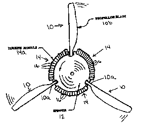
Fig. 1 is a somewhat diagrammatic front elevation view
showing a propeller spinner with turbine modules of the
invention mounted thereon;
Fig. 2 is a perspective view showing an actual turbine
module of the invention;
Fig. 3 is a perspective view showing the turbine module
of Fig. 2 mounted on a propeller spinner;
2
CA 02336021 2000-12-27
WO 99/67507 PCT/US99/I4184
Fig. 4 is a front elevation view showing portions of a
turbine module of the invention;
Fig. 5 is a fragmentary top plan view of the module of
Fig. 4;
Fig. 6 is a sectional view taken aloag lines 6-6 of
Fig. 4;
Fig. 7 is a top plan view showing the profile of one
type of turbine vanes in accordance with the invention;
Fig. 8 is a top plan view showing the profile of
another type of turbine vanes in accordance with the
invention; and
Fig. 9 is an explanatory diagram.
DETAILED DESCRIPTION OF THE INVENTION
As shown in fig. 1, in accordance with the invention, a
device and method for contributing propulsive thrust to a
propeller 10 on a spinner 12 employs a turbine 14 adapted to
be mounted on the spinner and having a plurality of turbine
vanes 16 disposed along the periphery of the spinner when
the turbine is so mounted. The turbine is constructed to
convert spinner rotational energy into a contribution to
propulsive thrust provided by the propeller. Unlike
conventional turbines employed in aircraft engines, the
turbine employed in the invention has no stator.
In the embodiment shown in Fig. l, the turbine
comprises a plurality of turbine modules 14a mounted on the
periphery of an aircraft propeller spinner between root
3
CA 02336021 2000-12-27
WO 99/67507 PCT/US99/14184
portions l0a of propeller blades lOb extending from the
spinner. In Fig. 1, the spinner has three propeller blades
spaced equidistantly around the periphery of the spinner,
and there are three turbine modules mounted on the spinner,
but the number of propeller blades and the number of turbine
modules is not limited to three.
As shown.in Figs. 2-4, each turbine module, which may
be formed of aluminum, for example, comprises a curved row
of turbine vanes 16 held between a curved base plate 18 and
a curved outer plate 20. In the form shown, each module
contains sixteen vanes. In the present embodiments, the
vanes are straight from top to bottom, i.e., untwisted. The
number, shape, and dimensions of the vanes can be optimized
for a given propeller and spinner combination.
The base plate 18 is curved to the spinner radius and
is designed to lie flush with the spinner surface. For
example, the base plate may have a radius of 8 inches, a
length of 13.75 inches, a width of 1.25 inches, and a
thickness of 0.051 inch. The leading edge region of the
base plate (e. g., 0.25 inch) is preferably tapered so that
the thickness of the base plate is a minimum at the leading
edge extremity. The outer plate may, for example, have a
radius of 11 inches, and a length of 18.25 inches, a width
of 1.0 inch, and a thickness of 0.051 inch.
Successive vanes 16 in each module are equally spaced
along the length of the module to define fluid flow channels
21. The leading ends of successive vanes may be spaced
4
CA 02336021 2000-12-27
WO 99/67507 PCT/US99/14184
apart by about 0.75 inch, for example. The vanes are
angulated with respect to the length of the row of vanes.
For example, each vane may form an angle of about 60 degrees
with respect to the length of the row. The radial vane
height may be approximately 3 inches, for example, and is
preferably substantially less than the radius of the
spinner. The vanes have curved airfoil surfaces that are
designed for smooth fluid flow through the channels 21.
As shown in Fig. 7, the vanes 16 may be formed of sheet
material approximately 0.025 in. gage and bent to an
approximately 30 degree arc around a leading edge rod 22,
the trailing edge being split around a trailing edge rod 22
to form a nozzle 26 with an adjacent vane.
Instead of vanes bent from sheet material as shown a.n
Fig. 7, the vanes may be machined from block material or
molded to provide the vane profile shown at 16a in Fig. 8.
The turbine module can be assembled using a series of
rods 22, as shown in Figs. 4-6, and can be attached to the
flange of the spinner back plate by screws 24. For
simplicity and clarity of illustration, in Fig. 4 an
arrangement of rods 22 is shown without the vanes, one of
which is shown in Fig. 6. Rods may have heads that are
countersunk into holes in the base plate and bonded into the
base plate by a suitable adhesive, and/or rods may be staked
and bonded into holes in the base plate. At least some of
the rods may extend through holes in the outer plate and be
threaded to receive nuts 25. Other rods may be inserted
5
CA 02336021 2000-12-27
WO 99/67507 PCT/US99/14184
into holes in the outer plate and remain flush to the outer
plate surface. The outer plate prevents vane tip vortex
losses and holds the vanes to the spinner against
centrifugal forces.
In an alternative construction, attachment of solid
vanes (e. g., Fig. 8) to the base plate and the outer plate
can be by means of screws countersunk into the base plate
and the outer plate. In still another alternative
construction, the entire turbine module can be formed of
plastic. Each vane may have upper and lower protrusions
that fit within corresponding holes in the base plate and
the outer plate.
The device of the invention operates on unprocessed
air, as a pump, to convert spinner rotational energy into a
contribution to propulsive thrust. As shown in Fig. 9, the
vanes are aligned to the cruise velocity vector VR resulting
from the vehicle velocity V" plus a spinner increment VS, and
orthogonal spinner rotational velocity VY. VR = Vinlet~ which
is the inlet velocity of the fluid entering the channels 21
defined between successive vanes. The invention is
preferably custom-tailored to an aircraft/engine/propeller
combination. Off-design speeds for other flight regimes
produce a thrust contribution but with lower efficiency.
By virtue of the nozzles 26 formed by the trailing
edges of the vanes, there is an increase in the exit
velocity V~it of the fluid exiting from the channels 21
6
CA 02336021 2000-12-27
WO 99/67507 PCT/US99/14184
defined between successive vanes, providing numerous jets
that add a gross thrust increment.
The invention can be applied to fixed pitch or constant
speed aircraft propellers, for example. With a constant
speed aircraft propeller, the cruise power settings of the
aircraft engine yield a fixed torque. Adding the turbine
torque requires that the propeller blades unload by
adjusting to a lower pitch to maintain constant RPM. The
lower pitch produces less drag, which is equivalent to
adding positive thrust. With the invention, a pilot has the
option of enjoying an increase in speed, or by throttling
back to the handbook cruise speed (specified without the
turbine) enjoying a decreased fuel burn and extended range.
Summarizing, benefits of the invention include:
1. The ability to absorb more power.
2. Improved engine cooling airflow, where the turbine
vanes cross over cooling entrance ducts.
3. Lower propeller noise (lower RPM for the same power
with fixed pitch propeller or with flatter pitch of constant
speed propeller).
4. Lower fuel flow for the original handbook cruise
airspeed.
5. Increased range.
6. Increased cruise speed (slight increase in power
for fixed pitch propeller; no increase in power for constant
speed propeller).
7
CA 02336021 2000-12-27
WO 99/67507 PCT/US99/I4184
7. Increased propulsive thrust (decrease of propeller
blade drag for constant speed propeller).
The invention is applicable to both pusher-type and
puller-type aircraft propellers and may be appropriate for
marine use in certain circumstances. Although the invention
has been described as a device to be added to an existing
spinner, spinners can be designed initially to incorporate
the turbine modules of the invention.
While preferred embodiments of the invention have been
shown and described, modifications can be made without
departing from the principles and spirit of the invention,
the scope of which is defined in the following claims.
8