Language selection

Search

Patent 2336124 Summary

Third-party information liability

Some of the information on this Web page has been provided by external sources. The Government of Canada is not responsible for the accuracy, reliability or currency of the information supplied by external sources. Users wishing to rely upon this information should consult directly with the source of the information. Content provided by external sources is not subject to official languages, privacy and accessibility requirements.

Claims and Abstract availability

Any discrepancies in the text and image of the Claims and Abstract are due to differing posting times. Text of the Claims and Abstract are posted:

  • At the time the application is open to public inspection;
  • At the time of issue of the patent (grant).
(12) Patent: (11) CA 2336124
(54) English Title: COLLECTOR OF UNUSED WATER
(54) French Title: COLLECTEUR POUR EAU INUTILISEE
Status: Term Expired - Post Grant Beyond Limit
Bibliographic Data
(51) International Patent Classification (IPC):
  • E03C 01/122 (2006.01)
  • E03B 01/04 (2006.01)
(72) Inventors :
  • NAOUM, DIMITRIOS (Greece)
(73) Owners :
  • DIMITRIOS NAOUM
(71) Applicants :
  • DIMITRIOS NAOUM (Greece)
(74) Agent: BORDEN LADNER GERVAIS LLP
(74) Associate agent:
(45) Issued: 2009-03-10
(86) PCT Filing Date: 1999-07-05
(87) Open to Public Inspection: 2000-01-20
Examination requested: 2004-06-02
Availability of licence: N/A
Dedicated to the Public: N/A
(25) Language of filing: English

Patent Cooperation Treaty (PCT): Yes
(86) PCT Filing Number: PCT/GR1999/000024
(87) International Publication Number: GR1999000024
(85) National Entry: 2000-12-28

(30) Application Priority Data:
Application No. Country/Territory Date
980100268 (Greece) 1998-07-09

Abstracts

English Abstract


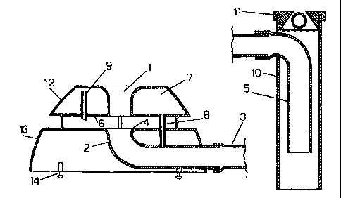
It is a device which is placed underneath all kinds of taps and collects the
pure unused water which escapes during the intermediate
intervals of a use. The device consists of two spherical sections (12 and 13)
firmly connected to each other, having internally various
constructions and components (1, 2, 4, 6, 7, 8, 9, 14), with the purpose of
collecting the clean water and of preventing the entry of the used
water into the head of the collector. The rest of it consists of a very
flexible pipe (3) which drives the water outside the place of use and
of the drain (10, 5, 11) which leads it to the storage area. The collection of
the water is achieved by taking advantage of the concentrated
energy of the column of the water at one point (when we turn on the tap) when
we do not use it. The opposite prevents the entry of the
used water. The invention is to be used both for household uses (kitchen,
bathroom) and places of personal hygiene for the personnel of
small and big factories, etc.


French Abstract

Cet appareil, pouvant être installé en dessous de n'importe quel type de robinet et destiné à recueillir l'eau pure inutilisée entre deux utilisations, est constitué de deux pièces sphériques (12, 13) solidement assujetties l'une à l'autre et renfermant diverses structures et constituants (1, 2, 4, 6, 7, 8, 9, 14), servant à recueillir l'eau saine et à empêcher les eaux usées de pénétrer dans la tête du collecteur. L'appareil comporte également un tuyau très souple (3) entraînant l'eau hors de l'emplacement d'utilisation et un tuyau d'évacuation (10, 5, 11) amenant cette eau dans une zone de stockage. Cette collecte d'eau est rendue possible par l'existence d'une concentration d'énergie dans la colonne d'eau en un point donné (lorsque l'on actionne le robinet) alors que l'on n'est pas en train de tirer de l'eau. L'action opposée empêche l'eau usée d'entrer. Cet appareil peut équiper aussi bien des maisons particulières à des fins domestiques (cuisine, salle de bain) que des usines, petites ou grandes, aux fins de l'hygiène personnelle des employés.

Claims

Note: Claims are shown in the official language in which they were submitted.


THE EMBODIMENTS OF THE INVENTION IN WHICH AN EXCLUSIVE
PROPERTY OR PRIVILEGE IS CLAIMED ARE DEFINED AS FOLLOWS:
1. A collector of unused water comprising: a head and a remaining part; the
head
comprising small and large sections; the small section constituting the upper
part of the
head of the collector and comprising a regulator for incoming water and having
in its
center a through hole having lips which are curved at the top, a water tank
having an inlet
during the filling and an outlet with overflow for the filling of an inlet
pipe with water,
and a water disturbance absorber; the large section constituting the base of
the head of the
collector and carrying anti-skid legs, an open-turn pipe having upper lips
which are
slightly curved, and a small cross-section pipe connecting the open-turn pipe
to the water
tank; and the remaining part comprising a flexible pipe connecting the head to
a drain, the
drain comprising a pipe inside of which extends an open-turn elbow with an
extension
along the run of the pipe and a side inlet, and an overflow valve in the upper
part of the
drain, the drain being connected, with or without a flexible pipe, to a water
storage tank.
2. A collector of unused water according to claim 1, including a base ring to
better
secure the collector in case of a larger cross-section drain.
3. A collector of unused water according to any one of claims 1 and 2,
including a
short bent extension which can fit in a tap to improve the verticality of the
column of
water.
4. A collector of unused water according to any one of claims 1 and 2,
including a
bent inlet water pipe which can fit in the water inlet of the upper part of
the collector to
draw water in case the column of the water is close to the walls of a
washbowl.
5. A collector of unused water according to any one of claims 1 and 2,
including
small similar tanks that can be used together or separately.
6. A collector of unused water according to any one of claims 1 and 2,
including a
large capacity tank which occupies the empty space of the lower part of a
bathtub or the
back side of a washbowl.

Description

Note: Descriptions are shown in the official language in which they were submitted.


CA 02336124 2000-12-28
WO 00/03098 PCT/GR99/00024
Collector of Unused Water
The invention pertains to a collector of unused water consisting of the head
and the
remaining part. The head consists of two spherical sections firmly connected
to
each other: 1) a small one which constitutes the upper part of the head of the
collector and is simultaneously a) a regulator of the incoming water, having
in its
center a through hole whose lips are curved at the top, b) a water tank,
having an
inlet and an outlet with overflow for the filling.of the inlet pipe with water
and c) a
water disturbance absorber from below. 2) A big one, which is the base of the
head
of the collector, carrying four anti-skid legs of adjustable height for the
levelling of
the head of the collector and an open-turn pipe which is connected to the
water tank
which is in the upper part of the head with a small cross-section pipe.
The remaining part consists of a very flexible pipe connecting the head to the
drain,
which consists of a pipe inside which there is an open-turn elbow with an
extension
along the run of the pipe and a side inlet. In the upper part there is an
overflow
valve. The drain is connected through a flexible pipe to the water storage
tank.
From time to time, attempts have been made to lower water consumption,
especially
that of the households. Mechanisms and ways have been invented, some of which
lower the pressure of the water and create spray by inserting air in the
pipes, thus
creating the impression of quantity while in others there are reduced cross-
sections
in the water intake pipes (thermomixing sluice valves) where the typical
position for
use is either open or close, making it impossible for the user to choose
another
position in between. There are also electromechanical or mechanical switches
at the
end of the tap.
These mechanisms have the following essential drawbacks:
1) Spray filters need frequent maintenance (screen cleaning.)

CA 02336124 2000-12-28
WO 00/03098 PCT/GR99/00024
2
2) The reduced cross-sections in the thermomixing sluice valves do not provide
economy, they just reduce the waste since they usually function only when
fully
open.
3) Taps with electromechanical mechanisms cost a lot to buy, require an
electric
installation all the way to the tap and cannot respond to the multiplicity of
household uses. They are, however, suitable for public places with simple uses
(washing of hands) and are installed mainly for hygienic purposes.
4) The mechanical mechanisms at the end of the tap not only are they not
convenient for the user (the switch is activated by a flexible foil, or
something
similar, hanging from the tap and hampers most uses) but they also inflict
hydraulic
damage on the installation due to their abrupt opening and closing.
The dominant mechanisms for water economy to-date are those which create spray
water in a variety of ways, giving the impression of quantity. The water saved
in
this way is little because 1) after the first impressions have subsided, the
user seeks
the weight of the water he was used to, which leads to a prolongation of the
time of
the use or the increase in the water flow; 2) the main problem, which is the
leak of
pure water during the intermediate stages of a use, is not countered.
Usually, the user either does not reach to turn off the tap during the time he
is not
using the water, e.g., when washing his hands or shaving, or does not have the
time
to do so because the time periods are too short, e.g., when washing his face
or
because he does not wish to alter the water mix in simple taps. The result is
that the
water wasted in the intermediate stages, when it is not used, is, as a rule,
more than
the water needed for the use itself. A noteworthy case of water wasting is the
one in
which we turn on the hot water switch and wait for it to come from the heater.
If,
furthermore, we have a solar heater, then the waste is especially big.
Thus was born the idea of collecting this pure unused water to be used
elsewhere.
This is achieved with the collector of unused water, through which the water
is
diverted to a tank or a storage place in order to be used.

CA 02336124 2000-12-28
WO 00/03098 PCT/GR99/00024
3
Drawing (1) shows the collector of unused water. Its function is illustrated
below.
The water passes through the regulator (1) of the incoming water flow. The
lips of
the regulator are curved so that the water enters the pipe (2) without having
its flow
obstracted even in the event that the column of water is not exactly in the
center or
diverses a little with the increase of the water supply if the tap has a
declination.
Then the water, with the power it carries, fills the open-turn elbow (2), the
elastic
pipe (3) and the open-turn elbow (5). As soon as this happens, there is
pressure and
we have an intense water rip in the mouth of the open turn elbow (2). The lips
of
the mouth of the open turn elbow (2) are slightly curved (4) so that the rip
is
reflected to and damped in the lower part (6) of the small spherical section
of the
head of the collector. Then we have an outflow of water from the extension of
the
open-turn elbow (5). At the same time, tank (7) is filled through pipe (8) and
when
this is done there is an outflow of water from the overflow pipe (9). The
waste pipe
(10) plays a triple role: 1) It leads the collected water, through an elastic
pipe or
without one, to a storage place; 2) It does not allow an uptake (during the
stoppage
of the water column from the tap to the head of the collector) of the water
inside the
elastic pipe; 3) it has on its upper part an overflow valve (11) which when
closed
does not allow any more water inside the drain pipe (10) when the water
storage
place is full.
The stage of the creation of the column of water from the turning on of the
tap until
the outflow from the open-turn pipe (5) lasts about 0.35 sec. During the
stoppage
stage, e.g., when we put our hands under the tap in order to rinse them, the
dirty
water cannot enter the head of the collector for two reasons: 1) the water
does not
have the power to push the water which is inside the open-turn elbow (2) and
the
elastic pipe (3) since it runs diffusely and 2) with the stoppage of the water
column,
the water inside the elastic pipe (3) returns and empties over the lips (4) of
the open-
turn elbow (2), flushing from the head of the collector the dirty water
running at the
moment. Even when the flushing lasts a long time, dirty water cannot enter
because

CA 02336124 2000-12-28
WO 00/03098 PCT/GR99/00024
4
there still is water in part of pipe (3) and in the open-turn elbow (2) (a
pipette is
created.) The level of the remaining water does not reach the lips (4) of the
open-
turn elbow (2), but stays lower, because the great speed of the water during
the
emptying of pipe (3) forces the water, which would normally cover the pipette
if it
returned slowly, to overflow. This water covers the water which is inside tank
(7)
(volume of about 20 cm3) which empties through pipe (8) and adds to it the
amount
missing to achieve an overflow through lips (4), thus preventing dirty water
from
entering the open-turn elbow (2).
The collector of unused water functions extremely effectively even with a very
small water flow, of the order of 2.8 L/min., and the lowest tap possible. It
is
designed so as to have its maximum performance at little and medium water flow
(small and medium tap opening), as shown in the output curve of Figure 2. As
for
the particular cases where there is a drain of bigger cross-section in the
kitchen sink
(e.g., existence of a garbage disposal unit) and the path of the outflow mouth
of the
tap happens to pass close to the periphery of the drain so that the four anti-
skid legs
(14) of the head of the collector cannot be solidly attached when it is placed
under
the mouth of the tap, a simple ring of bigger diameter than the base of the
collector
is placed on the base of the collector (13), thus moving the four anti-skid
legs to a
new base of a bigger diameter.
Also, in case the column of water is too close to the walls of the sink, a
short bent
tube can be placed in such a way as to reach and fit the water inlet of the
head of the
collector (1).
Finally, in case of great inclination of the tap, it is suggested that a short
bent
extension be placed at the end of the tap to achieve better verticality.
Figure (3) illustrates certain facts pertaining to specific everyday household
uses.
The measurements were made with conservative use of a simple tap whose outflow

CA 02336124 2000-12-28
WO 00/03098 PCT/GR99/00024
mouth was 39 cm. above the bottom of the sink. The water supply network
pressure
was 1.8 BAR at periods of rest and the internal diameter of the two open-turn
elbows (2) and (5) as well as that of the flexible pipe (3) was 10 mm. These
measurements did not take into account the fact that in each of the uses, as
long as
5 they were not too close to each other in time, there is an amount of water
added to
the collected one due to the wait for hot water during the winter.
The overall consumption of water, regardless of use, is indicative as it
depents
exclusively on the user. The numbers in the other columns are interesting.
Looking, for example, at the use - face washing - we see that when we consume
3.3L, only 0.8L are used for the actual use. The remaining 2.5L are wasted
during
the intermediate times. The collector of unused water can collect the 1.6L of
these
2.5L. We, therefore, save 64% of the water which was not used in this
particular
use or a 48.5% economy in the water in the overall use of the paradigm without
shortening the time of use. In case there is a period of wait for hot water,
the
amount of collected water is much greater.
The collector of unused water is suitable both for household use (kitchen,
bathroom) and for spaces of personal hygiene in small and big factories, etc.,
without it being binding.
The collector of unused water is a device of small volume, light, handy and
can be
installed in all kinds of lavatory washbowls, kitchen sinks or places having
to do
with personal hygiene. The only thing a user has to do, is to place the head
of the
collector of unused water under the tap. The head of the collector can be
moved
and placed beside the tap, e.g., when we want to clean the place, very simply
and
easily.
The collector of unused water is a device with low manufacturing cost, simple
and
in need of no maintenance.

CA 02336124 2000-12-28
WO 00/03098 PCT/GR99/00024
6
There are various solutions to the problems of storage and distribution of the
water.
The size and the shape of the tank(-s) as well as the hauling of the water are
variables which we can modify to suit the solution we wish to achieve. The use
of
bigger spaces such as the lower part of the bathtub or the washbowl gives us
the
ability to store more liters of water. The use of small pumps or pumps
controlled by
pressureless mechanisms to haul the water further away or to higher points
such as
the water tank in the closet above the lavatory allows us greater flexibility.
Of course, the simple and economical solution of placing a bucket by the
collection
point for immediate use is by no means ruled out.
Below are described two ways of application of the invention, with references
to the
drawings, which are in no way restrictive.
Example 1
Application in household use
In the bathroom (Figure 4)
The layout shows: the collector of unused water, two lOL tanks (suggested
dimensions: 0.20x0.35x0.15m.), a plastic pipe and a water level switch. The
height
of the tank (2) is less or equal to the difference between the height of the
lip of the
washbowl from the floor and the height of the level of the water in the water-
closet
from the floor. The water is gathered by the collector of unused water and
driven to
tank (2). The water stored in this tank is exclusively for the flush water-
closet.
When this is filled, the water overflows and fills tank (3) from which it can
be used
to clean the house, for instance.
When the water from the water-closet empties, switch (4) opens and the water
from
tank (2) empties into the water-closet due to gravity.

CA 02336124 2000-12-28
WO 00/03098 PCT/GR99/00024
7
The amount of water which can be collected in the bathroom in a family of four
can
be deduced approximately by using the facts in the last column of Figure 3:
hand washing 8 uses x 1.2L = 9.6L
face washing 8 uses x 1.6L = 12.8L
teeth brushing 8 uses x 1.2L = 9.6L
shaving 2 uses x 1.OL = 2.OL
wait for hot water estimated = 5.OL
house cleaning intermediate 5 uses x 1.2L = 6.OL
uses
Total 45L
In the kitchen (Figure 5)
The collection and storage of water in the kitchen is done in a similar way.
The
tank can be installed underneath the kitchen sink. A sluice valve is fitted in
the
lower part of the tank, from which we can get the collected water. The
quantity of
the water gathered in the kitchen of a house of a family of four, which uses a
dishwasher, has been measured and it amounts, overall, for a whole day, to
approximately 25L.
Therefore, the water collected daily appears to be in the order of 70L. This
means
that with the water we have collected we can cover our daily needs for the
water-
closet (with rational use) and the cleaning of the house.
For a family of four with an average consumption of 35m3 per quarter, this
amounts
to a water economy of 70L x 120 days = 8,400L, or 8.4m3, which amounts to a
24%
reduction in the overall consumption of water.
Example 2
In places of personal hygiene in large and small factories, etc.

CA 02336124 2000-12-28
WO 00/03098 PCT/GR99/00024
8
Due to the nature of the work, most of the time individual hygiene is
particularly
time-consuming and, consequently, the quantity of the collected water is
large. The
water can be collected with lined-up collectors of unused water and led to a
common pipe which will fill a water tank that will supply the bathrooms or
other
needy places of the enterprise. The layout is shown in Figure 6.

Representative Drawing
A single figure which represents the drawing illustrating the invention.
Administrative Status

2024-08-01:As part of the Next Generation Patents (NGP) transition, the Canadian Patents Database (CPD) now contains a more detailed Event History, which replicates the Event Log of our new back-office solution.

Please note that "Inactive:" events refers to events no longer in use in our new back-office solution.

For a clearer understanding of the status of the application/patent presented on this page, the site Disclaimer , as well as the definitions for Patent , Event History , Maintenance Fee  and Payment History  should be consulted.

Event History

Description Date
Inactive: Expired (new Act pat) 2019-07-05
Change of Address or Method of Correspondence Request Received 2018-03-12
Inactive: Late MF processed 2016-07-26
Maintenance Request Received 2016-07-26
Letter Sent 2016-07-05
Inactive: Late MF processed 2010-07-07
Letter Sent 2010-07-05
Grant by Issuance 2009-03-10
Inactive: Cover page published 2009-03-09
Inactive: Office letter 2009-01-05
Notice of Allowance is Issued 2009-01-05
Inactive: Approved for allowance (AFA) 2008-09-02
Letter Sent 2008-09-02
Letter Sent 2008-08-22
Final Fee Paid and Application Reinstated 2008-08-13
Reinstatement Requirements Deemed Compliant for All Abandonment Reasons 2008-08-13
Pre-grant 2008-08-13
Withdraw from Allowance 2008-08-13
Reinstatement Request Received 2008-08-13
Deemed Abandoned - Failure to Respond to Maintenance Fee Notice 2008-07-07
Deemed Abandoned - Conditions for Grant Determined Not Compliant 2008-03-25
Notice of Allowance is Issued 2007-09-25
Letter Sent 2007-09-25
Inactive: Approved for allowance (AFA) 2007-08-30
Amendment Received - Voluntary Amendment 2007-07-04
Inactive: S.30(2) Rules - Examiner requisition 2007-01-05
Inactive: IPC from MCD 2006-03-12
Letter Sent 2004-11-08
Inactive: Delete abandonment 2004-11-08
Inactive: Abandon-RFE+Late fee unpaid-Correspondence sent 2004-07-05
Request for Examination Requirements Determined Compliant 2004-06-02
All Requirements for Examination Determined Compliant 2004-06-02
Inactive: MF/reinstatement fee unallocated - Log 25 deleted 2003-07-30
Inactive: Acknowledgment of reinstatement not sent 2003-07-30
Inactive: MF/reinstatement fee unallocated - Log 25 deleted 2003-07-30
Letter Sent 2003-07-15
Reinstatement Requirements Deemed Compliant for All Abandonment Reasons 2003-06-20
Deemed Abandoned - Failure to Respond to Maintenance Fee Notice 2002-07-05
Inactive: Cover page published 2001-04-10
Inactive: First IPC assigned 2001-03-29
Inactive: Inventor deleted 2001-03-20
Inactive: Notice - National entry - No RFE 2001-03-20
Application Received - PCT 2001-03-15
Small Entity Declaration Determined Compliant 2000-12-28
Application Published (Open to Public Inspection) 2000-01-20

Abandonment History

Abandonment Date Reason Reinstatement Date
2008-08-13
2008-07-07
2008-03-25
2002-07-05

Maintenance Fee

The last payment was received on 2008-08-13

Note : If the full payment has not been received on or before the date indicated, a further fee may be required which may be one of the following

  • the reinstatement fee;
  • the late payment fee; or
  • additional fee to reverse deemed expiry.

Patent fees are adjusted on the 1st of January every year. The amounts above are the current amounts if received by December 31 of the current year.
Please refer to the CIPO Patent Fees web page to see all current fee amounts.

Fee History

Fee Type Anniversary Year Due Date Paid Date
Basic national fee - small 2000-12-28
MF (application, 2nd anniv.) - small 02 2001-07-05 2001-06-13
MF (application, 3rd anniv.) - small 03 2002-07-05 2003-06-20
Reinstatement 2003-06-20
MF (application, 4th anniv.) - small 04 2003-07-07 2003-06-20
Request for examination - small 2004-06-02
MF (application, 5th anniv.) - small 05 2004-07-05 2004-06-02
MF (application, 6th anniv.) - small 06 2005-07-05 2005-06-16
MF (application, 7th anniv.) - small 07 2006-07-05 2006-06-12
MF (application, 8th anniv.) - small 08 2007-07-05 2007-07-04
Final fee - small 2008-08-13
Reinstatement 2008-08-13
MF (application, 9th anniv.) - small 09 2008-07-07 2008-08-13
MF (patent, 10th anniv.) - small 2009-07-06 2009-06-04
Reversal of deemed expiry 2016-07-05 2010-07-07
MF (patent, 11th anniv.) - small 2010-07-05 2010-07-07
MF (patent, 12th anniv.) - small 2011-07-05 2011-06-28
MF (patent, 13th anniv.) - small 2012-07-05 2012-06-29
MF (patent, 14th anniv.) - small 2013-07-05 2013-07-03
MF (patent, 15th anniv.) - small 2014-07-07 2014-06-27
MF (patent, 16th anniv.) - standard 2015-07-06 2015-06-30
MF (patent, 17th anniv.) - standard 2016-07-05 2016-07-26
Reversal of deemed expiry 2016-07-05 2016-07-26
MF (patent, 18th anniv.) - standard 2017-07-05 2017-06-05
MF (patent, 19th anniv.) - standard 2018-07-05 2018-07-05
Owners on Record

Note: Records showing the ownership history in alphabetical order.

Current Owners on Record
DIMITRIOS NAOUM
Past Owners on Record
None
Past Owners that do not appear in the "Owners on Record" listing will appear in other documentation within the application.
Documents

To view selected files, please enter reCAPTCHA code :


To view images, click a link in the Document Description column. To download the documents, select one or more checkboxes in the first column and then click the "Download Selected in PDF format (Zip Archive)" or the "Download Selected as Single PDF" button.

List of published and non-published patent-specific documents on the CPD .

If you have any difficulty accessing content, you can call the Client Service Centre at 1-866-997-1936 or send them an e-mail at CIPO Client Service Centre.


Document
Description 
Date
(yyyy-mm-dd) 
Number of pages   Size of Image (KB) 
Representative drawing 2001-04-09 1 9
Abstract 2000-12-27 1 47
Description 2000-12-27 8 339
Claims 2000-12-27 2 64
Drawings 2000-12-27 3 61
Claims 2007-07-03 1 47
Representative drawing 2009-02-12 1 10
Reminder of maintenance fee due 2001-03-19 1 112
Notice of National Entry 2001-03-19 1 194
Courtesy - Abandonment Letter (Maintenance Fee) 2002-08-04 1 183
Notice of Reinstatement 2003-07-14 1 165
Reminder - Request for Examination 2004-03-07 1 116
Acknowledgement of Request for Examination 2004-11-07 1 177
Commissioner's Notice - Application Found Allowable 2007-09-24 1 164
Courtesy - Abandonment Letter (NOA) 2008-06-16 1 165
Notice of Reinstatement 2008-08-21 1 170
Courtesy - Abandonment Letter (Maintenance Fee) 2008-09-01 1 172
Notice of Reinstatement 2008-09-01 1 164
Maintenance Fee Notice 2010-07-06 1 170
Late Payment Acknowledgement 2010-07-06 1 163
Maintenance Fee Notice 2016-08-07 1 180
Late Payment Acknowledgement 2016-08-07 1 165
Fees 2012-06-28 1 156
Fees 2013-07-02 1 156
PCT 2000-12-27 4 133
Fees 2003-06-19 2 42
Fees 2001-06-12 1 36
Fees 2004-06-01 2 51
Fees 2005-06-15 1 40
Fees 2006-06-11 1 46
Fees 2007-07-03 1 48
Fees 2008-08-12 1 42
Correspondence 2009-01-04 1 17
Fees 2009-06-03 1 200
Fees 2010-07-06 1 200
Fees 2011-06-27 1 202
Fees 2014-06-26 1 25
Fees 2015-06-29 1 26
Maintenance fee payment 2016-07-25 1 26