Language selection

Search

Patent 2336215 Summary

Third-party information liability

Some of the information on this Web page has been provided by external sources. The Government of Canada is not responsible for the accuracy, reliability or currency of the information supplied by external sources. Users wishing to rely upon this information should consult directly with the source of the information. Content provided by external sources is not subject to official languages, privacy and accessibility requirements.

Claims and Abstract availability

Any discrepancies in the text and image of the Claims and Abstract are due to differing posting times. Text of the Claims and Abstract are posted:

  • At the time the application is open to public inspection;
  • At the time of issue of the patent (grant).
(12) Patent: (11) CA 2336215
(54) English Title: BARBECUE LIGHT
(54) French Title: DISPOSITIF SERVANT A ECLAIRER UN BARBECUE
Status: Expired and beyond the Period of Reversal
Bibliographic Data
(51) International Patent Classification (IPC):
  • F21V 33/00 (2006.01)
  • A47J 37/07 (2006.01)
  • F21S 9/02 (2006.01)
  • F27D 21/02 (2006.01)
(72) Inventors :
  • GRISAMORE, GREG E. (United States of America)
  • GATES, JAMES R. (United States of America)
(73) Owners :
  • GREG E. GRISAMORE
  • JAMES R. GATES
(71) Applicants :
  • GREG E. GRISAMORE (United States of America)
  • JAMES R. GATES (United States of America)
(74) Agent: BORDEN LADNER GERVAIS LLP
(74) Associate agent:
(45) Issued: 2008-04-08
(86) PCT Filing Date: 1999-06-01
(87) Open to Public Inspection: 1999-12-23
Examination requested: 2004-05-14
Availability of licence: N/A
Dedicated to the Public: N/A
(25) Language of filing: English

Patent Cooperation Treaty (PCT): Yes
(86) PCT Filing Number: PCT/US1999/012175
(87) International Publication Number: WO 1999066278
(85) National Entry: 2000-12-18

(30) Application Priority Data:
Application No. Country/Territory Date
09/100,796 (United States of America) 1998-06-19

Abstracts

English Abstract


A handle assembly (11) mountable to a barbecue lid (13) and which
includes an integral light (21) positioned to shine upon the cooking surface
(24) of the barbecue (15) when the barbecue lid (13) has been so positioned
as to expose the cooking surface (24).


French Abstract

Ensemble poignée (11) pouvant être monté sur le couvercle (13) d'un barbecue et comprenant un éclairage solidaire (21) placé de façon à éclairer la surface de cuisson (24) du barbecue (15) quand le couvercle (13) de ce dernier a été placé de manière à découvrir cette surface de cuisson.

Claims

Note: Claims are shown in the official language in which they were submitted.

-5-
CLAIMS:
1. An apparatus comprising:
a handle assembly comprising an elongated tube adapted to be mounted to a lid
of
a barbecue and having an exterior surface shaped to provide a gripping surface
grippable
to open and close said lid, said handle assembly including a light source
mounted therein,
said tube including a light transmissive portion positioned to permit said
light source to
illuminate a cooking surface of the barbecue when said lid is in a position
which exposes
said cooking surface.
2. The apparatus of claim 1, further including mounting bracket means for
attaching
said handle assembly to said lid.
3. The apparatus of claim 1, wherein said tube includes a clear plastic outer
housing,
and an inner housing.
4. The apparatus of claim 3, wherein said inner housing is semicircular in
cross-
section and runs substantially the length of the tube.
5. The apparatus of claim 4, wherein said housing supports a plurality of
batteries,
first and second positive contact bars, and first and second lamp holders.
6. The apparatus of claim 4, wherein said housing includes first and second
side
channels and a base channel formed respectively by three pairs of projections.
7. The apparatus of claim 6, wherein one or more batteries are supported by
the
respective pairs of projections.
8. The apparatus of claim 7, further including first and second end caps
closing
respective ends of said tube.
9. The apparatus of claim 7, further including switch means for turning on and
off
light provided by said light source.

-6-
10. In combination:
a barbecue having a removable lid and a cooking surface disposed beneath said
lid
guard; and
a handle assembly comprising an elongated tube adapted to be mounted to the
lid
of the barbecue and having an exterior surface shaped to provide a gripping
surface
grippable to open and close said lid, said handle assembly including a light
source
mounted therein, said tube including a light transmissive portion positioned
to permit said
light source to illuminate said cooking surface when said lid is in a position
which exposes
said cooking surface.
11. The apparatus of claim 10, further including mounting bracket means for
attaching
said handle assembly to said lid.
12. The apparatus of claim 11, wherein said tube includes a clear plastic
outer housing,
and an inner housing.
13. The apparatus of claim 12, wherein said inner housing is semicircular in
cross-
section and runs substantially the length of the tube.
14. The apparatus of claim 13, wherein said housing includes first and second
side
channels and a base channel formed respectively by three pairs of projections.
15. The apparatus of claim 14, wherein one or more batteries are supported by
the
respective pairs of projections.
16. The apparatus of claim 15, further including first and second end caps
closing
respective ends of said tube.
17. An apparatus comprising:
a handle assembly comprising an elongated cylindrical clear plastic outer tube
adapted to be mounted to a lid of a barbecue, an inner housing of semicircular
cross-
section, said cross-section being of a radius selected that said inner housing
slides into said

-7-
cylindrical tube and mates flush with an inner surface thereof, said inner
housing including
a means for supporting a plurality of batteries therein and means for mounting
light source
therein, said tube including a light transmissive portion positioned to permit
said light
source to illuminate a cooking surface of the barbecue when said lid is in a
position which
exposes said cooking surface.
18. The apparatus of claim 17, further including mounting bracket means for
attached
said handle assembly to said lid.
19. The apparatus of claim 18, wherein said means for supporting includes
first and
second side channels and a base channel formed respectively by three pairs of
projections.
20. The apparatus of claim 19, further including first and second end caps
closing
respective ends of said tube.

Description

Note: Descriptions are shown in the official language in which they were submitted.


CA 02336215 2006-10-19
BARBECUE LIGHT
BACKGROUND OF '= INVENTION
The subject invention relates generaliy to a lighting apparatus and more
particularly to a combination handle/light assembly for barbecues.
The lighting of conventional barbecues so as to permit the cooking
surface to be viewed at night has presented considerable difficulties. Some
approaches
have included the provision of a tripod with lights mounted on it, attaching a
light to a
nearby post or wall, or attaching of a clamp-on bendable extension light to a
nearby tray
or other physical object. In addition to being cumbersome, awkward and
expensive,
such lighting arrangements are typically positioned such that shadows are cast
on the
cooking surface so as to obscure the desired view of food items being cooked.
Accordingly, it is an aim of the invention to provide an improved
barbecue lighting apparatus;
It is another aim of the invention to provide barbecue lighting
apparatus which is simple and convenient to use;
It is yet mother aim of the invention to provide barbecue lighting
apparatus which eliminates the shadow problems of the prior art.
These and other aims and advantages are achieved according to the
invention by provision of a handle assembly mountable to the barbecue lid
which
includes an inteeral light positioned to shine upon the cooking surface of the
barbecue
when the barbecue lid has been so positioned as to expose the cooking surface.
The
barbecue handlellight assembly is preferably mountable by removal of the
conventional
handle from the barbecue lid and attaching an assembly constructed according
to the

CA 02336215 2006-10-19
-2-
invention in place of the conventional handle. Alternatively, the handle may
be made
adaptable to be connected to the handle mounting hardware provided by the
manufacturer of the barbecue lid or otherwise attached.
According to one aspect of the present invention there is provided an
apparatus comprising a handle assembly comprising an elongated tube adapted to
be
mounted to a lid of a barbecue and having an exterior surface shaped to
provide a gripping
surface grippable to open and close said lid, said handle assembly including a
light source
mounted therein, said tube including a light transmissive portion positioned
to permit said
light source to illuminate a cooking surface of the barbecue when said lid is
in a position
which exposes said cooking surface.
According to another aspect of the present invention there is provided in
combination a barbecue having a removable lid and a cooking surface disposed
beneath
said lid guard; and a handle assembly comprising an elongated tube adapted to
be mounted
to the lid of the barbecue and having an exterior surface shaped to provide a
gripping
surface grippable to open and close said lid, said handle assembly including a
light source
mounted therein, said tube including a light transmissive portion positioned
to permit said
light source to illuminate said cooking surface when said lid is in a position
which exposes
said cooking surface.
According to a further aspect of the present invention there is provided an
apparatus comprising a handle assembly comprising an elongated cylindrical
clear plastic
outer tube adapted to be mounted to a lid of a barbecue, an inner housing of
semicircular
cross-section, said cross-section being of a radius selected that said inner
housing slides
into said cylindrical tube and mates flush with an inner surface thereof, said
inner housing
including a means for supporting a plurality of batteries therein and means
for mounting
light source therein, said tube including a light transmissive portion
positioned to permit
said light source to illuminate a cooking surface of the barbecue when said
lid is in a
position which exposes said cooking surface.

CA 02336215 2006-10-19
- 2a -
BRIEF DESCRIPTION OF THE DRAWINGS
The exact nature of this invention, as well as its objects and advantages,
will become readily apparent upon reference to the following detailed
description when
considered in conjunction with the accompanying drawings, in which like
reference
numerals designate like parts throughout the figures thereof, and wherein:
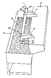
Figure 1 is a perspective view illustrating a barbecue light assembly
according to the preferred embodiment installed on a conventional barbecue;
Figure 2 is a side view of the tube portion of the assembly of Figure 1;
Figure 3 is an end view of an inner housing component according to the
preferred embodiment;
Figure 4 is a side view of the inner housing component of the preferred
embodiment with various interior components installed therein;
Figure 5 is a top view of Figure 4;
Figure 6 is a side view of a reflector component of the preferred
embodiment;
Figure 7 is a top view of the reflector component of Figure 4;
Figure 8 is an end view of the inner housing with battery installed;
Figure 9 is a cross-sectional view taken at 9-9 of Figure 2;
Figure 10 is a perspective view of a lamp retainer component;
Figure 11 is a side view of a positive contact bar component.
The following description is provided to enable any person skilled in the
art to make and use the invention and sets forth the preferred modes
contemplated by the
inventor of carrying out his invention. Various modifications, however, will
remain

CA 02336215 2000-12-18
WO 99/66278 PCT/US99/12175
-3-
readily apparent to those skilled in the art, since the general principles of
the present
invention have been defined herein specifically to provide a combination
handle/barbecue light assembly adapted for a particular type of barbecue and
employing
only one of many possible interior mounted light sources.
Figure 1 illustrates a combination handle/barbecue light assembly I1
attached to a pivotable lid 13 of a barbecue 15. The assembly 11 includes
first and
second mounting brackets 17, 19 shaped to position a light-containing tube 21
above the
cooking surface 24 of the barbecue 15. The mounting brackets 17, 19 may be
specially
designed or may be those provided as part of the barbecue. A single mounting
bracket
may also be used, for example, centrally positioned on the tube 21. The tube
21 may be
fixed to the brackets 17, 19 by conventional set screws 23, 25 or other
conventional
fastening means.
Figure 1 further illustrates an on/off switch 27 used to activate a light
source contained in tube 21. That light source is directed downwardly on the
surface 24
and is therefore not visible in the view of Figure 1.
The light-containing tube 21 is shown in more detail in Figure 2. The
tube 21 includes a clear plastic outer housing 67, an inner housing or
mounting cradle
31, and first and second end caps 61, 63. The mounting cradle 31 is a
semicircular
cross-section as shown in Figure 3 and runs substantially the length of the
tube 21. The
housing 31 supports four batteries 47, first and second positive contact bars
41 and first
and second lamp holders or retainers 51. As further illustrated in Figure 3,
the mounting
cradle 31 includes first and second side channels and a base channel formed
respectively
by pairs of projec$ons 33, 35, 37. The batteries 47 are supported by these
respective
pairs of projections 33, 35, 37, as particularly illustiated in Figure 8.
As illustrated in Figure 5, the positive contact bars 41 and the bulb
retainers 43 may be held in position by suitable crimps 49, 51 in the base
channel 37.
Other conventional means of retaining such components will, of course, be
apparent to
those skilled in the art.
Figures 6 and 7 illustrate a reflector component 53 of arcuately curved
cross-section and which includes apertures 55 positioned to permit insertion
of
respective lamps 45 therethrough. As shown in Figure 9, the reflector 53 is
retained in

CA 02336215 2000-12-18
WO 99/66278 PCTIUS99/12175
-4-
position by suitable underlying indentations in the top-most projection of
each of the
horizontal pairs of projections 33, 35. Figure 9 further illustrates the
respective shape
and positioning of the inner housing 31 within the outer housing 67 of the
tube 21. The
inner housing 31 is preferably a rigid extrusion of material such as vinyl and
is opaque
and of a dark color such as black. The outer housing 67 may be a clear plastic
tube.
Figure 10 illustrates a perspective view of the bulb retainer 43 and
particularly shows a lance element 71 conventionally used to interconnect with
a bulb or
lamp 45. The bulb retainer 43 includes first and second horizontal surfaces
73, 75
integrally formed with a vertical surface 81. Figure 1 i illustrates one of
the positive
contact bars 41 in greater detail. These components are connected by suitable
electrical
conductors to form an electric circuit such that switch 27 may turn the bulbs
45 or other
light source "on" or "off'. Such a circuit may be similar to a typical
flashlight or may
include a ballast for flourescent source.
Those skilled in the art will appreciate that various adaptations and
modifications of the just-described preferred embodiment can be configured
without
departing from the scope and spirit of the invention. For example, while one
particular
configuration for establishing a light-producing source within the tube 21 as
depicted in
Figures 2-5, various other well known light generation means may be used,
without
departing from the scope and spirit of the invention. Various attachment
mechanisms
may also be provided for attachment to various shapes and styles of barbecue
lids.
Therefore, it is to be understood that, within the scope of the appended
claims, the
invention may be practiced other than as specifically described-herein.

Representative Drawing
A single figure which represents the drawing illustrating the invention.
Administrative Status

2024-08-01:As part of the Next Generation Patents (NGP) transition, the Canadian Patents Database (CPD) now contains a more detailed Event History, which replicates the Event Log of our new back-office solution.

Please note that "Inactive:" events refers to events no longer in use in our new back-office solution.

For a clearer understanding of the status of the application/patent presented on this page, the site Disclaimer , as well as the definitions for Patent , Event History , Maintenance Fee  and Payment History  should be consulted.

Event History

Description Date
Time Limit for Reversal Expired 2010-06-01
Letter Sent 2009-06-01
Grant by Issuance 2008-04-08
Inactive: Cover page published 2008-04-07
Pre-grant 2008-01-18
Inactive: Final fee received 2008-01-18
Notice of Allowance is Issued 2007-07-20
Letter Sent 2007-07-20
Notice of Allowance is Issued 2007-07-20
Inactive: IPC removed 2007-06-28
Inactive: Approved for allowance (AFA) 2007-06-01
Amendment Received - Voluntary Amendment 2006-10-19
Inactive: S.30(2) Rules - Examiner requisition 2006-04-19
Inactive: IPC from MCD 2006-03-12
Letter Sent 2004-05-27
Request for Examination Requirements Determined Compliant 2004-05-14
All Requirements for Examination Determined Compliant 2004-05-14
Request for Examination Received 2004-05-14
Inactive: IPC assigned 2002-01-24
Inactive: First IPC assigned 2002-01-24
Inactive: Cover page published 2001-04-17
Inactive: First IPC assigned 2001-04-04
Inactive: Inventor deleted 2001-03-21
Inactive: Notice - National entry - No RFE 2001-03-21
Application Received - PCT 2001-03-16
Small Entity Declaration Determined Compliant 2000-12-18
Application Published (Open to Public Inspection) 1999-12-23

Abandonment History

There is no abandonment history.

Maintenance Fee

The last payment was received on 2007-05-18

Note : If the full payment has not been received on or before the date indicated, a further fee may be required which may be one of the following

  • the reinstatement fee;
  • the late payment fee; or
  • additional fee to reverse deemed expiry.

Please refer to the CIPO Patent Fees web page to see all current fee amounts.

Fee History

Fee Type Anniversary Year Due Date Paid Date
Basic national fee - small 2000-12-18
MF (application, 2nd anniv.) - small 02 2001-06-01 2001-05-22
MF (application, 3rd anniv.) - small 03 2002-06-03 2002-05-23
MF (application, 4th anniv.) - small 04 2003-06-02 2003-05-22
MF (application, 5th anniv.) - small 05 2004-06-01 2004-02-27
Request for examination - small 2004-05-14
MF (application, 6th anniv.) - small 06 2005-06-01 2005-05-30
MF (application, 7th anniv.) - small 07 2006-06-01 2006-05-10
MF (application, 8th anniv.) - small 08 2007-06-01 2007-05-18
Final fee - small 2008-01-18
MF (patent, 9th anniv.) - standard 2008-06-02 2008-05-28
Owners on Record

Note: Records showing the ownership history in alphabetical order.

Current Owners on Record
GREG E. GRISAMORE
JAMES R. GATES
Past Owners on Record
None
Past Owners that do not appear in the "Owners on Record" listing will appear in other documentation within the application.
Documents

To view selected files, please enter reCAPTCHA code :


To view images, click a link in the Document Description column. To download the documents, select one or more checkboxes in the first column and then click the "Download Selected in PDF format (Zip Archive)" or the "Download Selected as Single PDF" button.

List of published and non-published patent-specific documents on the CPD .

If you have any difficulty accessing content, you can call the Client Service Centre at 1-866-997-1936 or send them an e-mail at CIPO Client Service Centre.


Document
Description 
Date
(yyyy-mm-dd) 
Number of pages   Size of Image (KB) 
Representative drawing 2001-04-17 1 7
Cover Page 2001-04-17 1 30
Description 2000-12-18 4 188
Abstract 2000-12-18 1 40
Claims 2000-12-18 3 97
Drawings 2000-12-18 3 72
Claims 2006-10-19 3 91
Description 2006-10-19 5 224
Drawings 2006-10-19 3 65
Representative drawing 2007-06-13 1 7
Cover Page 2008-03-07 1 34
Reminder of maintenance fee due 2001-03-21 1 112
Notice of National Entry 2001-03-21 1 194
Reminder - Request for Examination 2004-02-03 1 113
Acknowledgement of Request for Examination 2004-05-27 1 176
Commissioner's Notice - Application Found Allowable 2007-07-20 1 164
Maintenance Fee Notice 2009-07-13 1 171
PCT 2000-12-18 6 262
Correspondence 2008-01-18 1 31