Language selection

Search

Patent 2336278 Summary

Third-party information liability

Some of the information on this Web page has been provided by external sources. The Government of Canada is not responsible for the accuracy, reliability or currency of the information supplied by external sources. Users wishing to rely upon this information should consult directly with the source of the information. Content provided by external sources is not subject to official languages, privacy and accessibility requirements.

Claims and Abstract availability

Any discrepancies in the text and image of the Claims and Abstract are due to differing posting times. Text of the Claims and Abstract are posted:

  • At the time the application is open to public inspection;
  • At the time of issue of the patent (grant).
(12) Patent: (11) CA 2336278
(54) English Title: ELECTRICALLY INSULATING RAIL PAD
(54) French Title: PLAQUE DE SEPARATION D'UN RAIL POUR ISOLATION ELECTRIQUE
Status: Expired and beyond the Period of Reversal
Bibliographic Data
(51) International Patent Classification (IPC):
  • E01B 09/68 (2006.01)
  • E01B 09/50 (2006.01)
(72) Inventors :
  • LARKE, ROGER DAVID (United Kingdom)
(73) Owners :
  • PANDROL LIMITED
(71) Applicants :
  • PANDROL LIMITED (United Kingdom)
(74) Agent: MARKS & CLERK
(74) Associate agent:
(45) Issued: 2009-12-08
(22) Filed Date: 2001-03-01
(41) Open to Public Inspection: 2001-09-24
Examination requested: 2005-01-28
Availability of licence: N/A
Dedicated to the Public: N/A
(25) Language of filing: English

Patent Cooperation Treaty (PCT): No

(30) Application Priority Data:
Application No. Country/Territory Date
0007300.7 (United Kingdom) 2000-03-24

Abstracts

English Abstract

A rail pad (1), for electrically isolating a railway rail (2), comprises a rail seat portion (11) for supporting a foot of the rail (2), a pair of upstands (12) joined to opposite edges of the rail seat portion (11) of the pad (1) by respective webs such that. respective channels (13) for directing water away from the rail are defined between the rail seat portion (11) of the pad (1) and each adjacent upstand (12). Such a pad provides improved wet electrical resistance.


French Abstract

Une plaque de séparation de rail (1), pour isoler électriquement un rail de chemin de fer (2), comprend un appui de rail (11) pour soutenir le pied du rail (2), une paire de rainures (12) jointes aux bords opposés de l'appui du rail (11) faisant partie de la plaque de séparation (1) par des réseaux respectifs de telle sorte que des canaux respectifs (13) pour faire dévier l'eau du rail sont définis entre l'appui du rail (11) de la plaque de séparation (1) et chaque rainure adjacente (12). Une telle plaque de séparation offre une meilleure résistance électrique à l'eau.

Claims

Note: Claims are shown in the official language in which they were submitted.

6
The embodiments of the invention in which an exclusive property or privilege
is claimed are defined as follows:
1. A rail pad, for use on a railway sleeper having a longitudinal axis, for
electrically
isolating a railway rail from the railway sleeper, the pad comprising a rail
seat portion
having a top surface for supporting a foot of the rail, wherein the pad
further
comprises a pair of upstands joined to opposite edges of the rail seat portion
of the
pad by respective webs each disposed at a level lower than that of the top
surface of
the rail seat portion, such that respective channels running normal to the
longitudinal
axis of the railway sleeper are defined between the rail seat portion of the
pad and
each adjacent upstand so that the channels constitute respective gutters
adapted to
direct water away from the rail, and wherein the pad overhangs at least one
edge of
the railway sleeper.
2. A rail pad as claimed in claim 1, further comprising a lip provided on the
underside
of at least that one of the edges of the pad which is to overhang the at least
one edge
of the railway sleeper.
3. A rail pad as claimed in claim 1, further comprising two pairs of spaced-
apart tabs
extending outwardly from opposite edges of the pad alongside the respective
channels, each pair of tabs forming therebetween a recess for receiving a rail
fastening
anchoring device.
4. A rail pad as claimed in claim 1, when used in a rail fastening assembly
including
respective electrical insulators, positioned between the rail and respective
rail
fastening anchoring devices, for additionally electrically insulating the rail
from the
rail fastening anchoring devices, wherein each of the insulators has a
respective lower
edge, and the height of each of the upstands is such that the upstand overlaps
the
lower edge of the adjacent insulator.
5. An assembly for electrically isolating a railway rail, the assembly
comprising a rail
pad as claimed in claim 1 and at least one insulator for location between the
rail and a
proximate rail fastening anchoring device, the insulator having a post portion
which
extends between the rail and the proximate rail fastening anchoring device,
and the

7
post portion of the insulator having a lower edge which is formed with a
downwardly-
extending tab, whereby when the insulator is in its operative configuration
the
downwardly-extending tab of the post portion is located within the associated
channel
of the rail pad.
6. An assembly as claimed in claim 5, wherein length of the downwardly-
extending
tab on the insulator is substantially equal to or greater than the width of
the proximate
rail fastening anchoring device.

Description

Note: Descriptions are shown in the official language in which they were submitted.


CA 02336278 2001-03-01
-1-
TITLE OF THE INVENTION
ELECTRICALLY INSULATING RAIL PAD
BACKGROUND OF THE INVENTION
The present invention relates to a rail pad for
electrically isolating a railway rail from an adjacent
rail fastening anchoring device (or shoulder) and a
rail foundation.
DESCRIPTION OF THE PRIOR ART
In modern railway systems many electrical signals,
for communication and rail traffic signalling purposes,
are passed along railway rails. In order to prevent
the conduction of such signals between the two rails,
insulating rail pads are provided beneath the rail foot
and insulators are provided between the rail foot and
adjacent shoulders.
With the increasing use of steel sleepers such
electrical insulation has become even more important.
It is of course vital that such insulators function not
only in dry conditions but also in wet conditions. A
rail fastening assembly incorporating a standard rail
pad is typically expected to have a wet electrical
resistance of at least 5 k Ohms. However, some track
operators require a far higher electrical resistance,
for example 20 k Ohms.
BRIEF SUMMARY OF THE INVENTION
According to a first aspect of the present
invention there is provided a rail pad for electrically
isolating a rai3way rail, the pad comprising a rail
seat portion for supporting a foot of the rail, wherein
the pad further comprises a pair of upstands joined to
opposite edges of the rail seat portion of the pad by
respective webs such that respective channels for
directing water away from the rail are defined between
the rail seat portion of the pad and each adjacent
upstand.

CA 02336278 2001-03-01
-2-
Such a pad, which can be used on either discrete
or continuous rail foundation, has an improved wet
electrical resistance compared with prior art pads,
since moisture falling on a rail fastening assembly in
which the pad is used will be directed away from the
assembly by the channels, in the manner of gutters.
Moreover, electrical path length is increased.
When used on a railway sleeper such that the said
channels run normal to the longitudinal axis of the
rail foundation, the pad preferably overhangs at least
one edge of the said rail foundation, thus directing
moisture away from the rail foundation.
Such a pad desirably further comprises a lip
provided on the underside of at least one of the edges
of the pad which is to overhang the edge of the railway
sleeper, allowing the pad to shed drips.
Desirably, the pad further comprises two pairs of
spaced-apart tabs extending from opposite edges of the
said pad alongside the said channels, each pair of tabs
forming a recess therebetween for receiving a railway
rail anchoring device, whereby the pad is located on
the rail foundation.
Preferably, when used in a rail fastening assembly
including electrical insulators, positioned between the
rail and respective rail fastening anchoring devices,
the height of each of the said upstands is such that
the upstand overlaps the lower edge of the adjacent
insulator, thereby further improving wet electrical
resistance of the pad.
According to a second aspect of the present
invention there is provided an assembly for
electrically isolating a railway rail, the assembly
comprising a rail pad in accordance with the first
aspect of the present invention and an insulator for
location between the rail and a rail fastening
anchoring device, the insulator having a post portion
which extends between the rail and the said rail

CA 02336278 2001-03-01
-3-
fastening anchoring device, a lower edge of which post
portion is formed with a downwardly-extending tab
whereby when the insulator is in its operative
configuration the tab is located within the channel of
the rail gad.
Preferably, the length of the said tab is
substantially equal to or greater than the width of the
said rail fastening device.
BRIEF DESCRIPTION OF THE DRAWINGS
Reference will now be made, by way of example, to
the accompanying drawings, in which:-
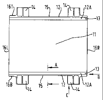
Figures 1A and 1B show respective plan and side
views of a rail pad embodying the first aspect of the
present invention;
Figures 2A, 2B and 2C show respective partial
views taken on lines A-A, B and C in Figure 1A; and
Figures 3A and 3B show respective partial cross-
sectional views of a rail fastening assembly
incorporating a rail pad embodying the first aspect of
the present invention and an insulator embodying the
second aspect of the present invention.
DETAILED DESCRIPTION OF THE INVENTION
As shown in Figures 1A, 1B, 2A, 2B and 2C, a rail
pad 1 embodying the first aspect of the present
invention comprises a rail seat portion 11 for
supporting a foot of a rail (rail foot not shown in
Figures lA to 2C). The rail seat portion 11 is
rectangular and along two opposite sides 16T, 16B
thereof, defined between the rail seat portion 11 and
respective upstands 12 which are connected by
respective webs 12A, it has channels 13. These
channels 13 are provided so as to allow water coming
into contact with the rail fastening assembly in which
the pad is used to be directed away from the rail in
the manner of a gutter and to increase electrical path
length. This embodiment is intended for use on a
railway sleeper, rather than on slab track, and

CA 02336278 2007-12-19
-4-
accordingly the width of the pad (normal to the axis of
the sleeper) is chosen to be such that each of its
sides 16L, 16R will overhang the sleeper edge, thereby
directing water away from the sleeper. Furthermore,
sides 16L and 16R of the rectangular pad 1 are provided
along their undersides with respective lips 17 (only
one of which is shown) to shed drips.
In order to locate the pad on the sleeper it is
provided with tabs 14, there being a pair of tabs 14
along each side 16T, 16B defining between them a recess
for receiving a rail fastening shoulder (not shown
in Figs. 1A to 2C) secured to the sleeper.
In one embodiment the pad is 210mm wide and across
each of its ends 16L, 16R is 162mm. Between the tabs
15 14 the pad has narrows to 158mm, the rail seat portion
being 140mm by 210mm. The width of the tabs 14 in the
recess 15 is 23mm. The depth of the pad at the rail
seat portion 11 is 10mm except at each end 16L and 16R
where the lip extends this by 3mm. The channels 13 are
7mm wide at their tops and 6mm deep.
Two examples of the use of the rail pad 1 are
shown in Figures 3A and 3B respectively. In each case,
the rail pad 1 is located beneath the foot of a rail 2
on a railway sleeper . The foot of the rail 2 sits on
the rail seat portion 11 of the rail pad 1. The rail
pad 1 is located between a pair of rail fastening
shoulders, 4A in Fig. 3A and 4B in Fig. 3B (only one of
each kind is shown in each Figure) such that the
shoulders 4A or 4B are located in the recesses 15.
Between the rail seat portion 11 of the rail pad 1 and
the adjacent shoulder 4A or 4B are the upstand 12 and
channel 13. Figure 3A illustrates the situation in
which an L-shaped insulator 5A is provided, having a
portion which rests on the rail 2. Figure 3B
illustrates a situation in which an insulator 5B is
located on the shoulder 4B. In each case the
insulators 5A, 5B have respective post portions 51A,

CA 02336278 2001-03-01
-5-
51B which extend between the shoulders 4A or 4B and the
rail 2. Each post portion 51A, 51B has a tab 52A, 52B
which extends into the channel 13 so there is
substantial overlap between the tab 52A, 52B and the
upstand 12, so as to further improve wet electrical
resistance.
Although the pad is shown as having a flat rail
seat portion, it may alternatively have a studded or
some other surface profile.
It is anticipated that a rail pad embodying the
present invention will have a wet electrical resistance
of at least 25 k Ohms.

Representative Drawing
A single figure which represents the drawing illustrating the invention.
Administrative Status

2024-08-01:As part of the Next Generation Patents (NGP) transition, the Canadian Patents Database (CPD) now contains a more detailed Event History, which replicates the Event Log of our new back-office solution.

Please note that "Inactive:" events refers to events no longer in use in our new back-office solution.

For a clearer understanding of the status of the application/patent presented on this page, the site Disclaimer , as well as the definitions for Patent , Event History , Maintenance Fee  and Payment History  should be consulted.

Event History

Description Date
Time Limit for Reversal Expired 2017-03-01
Letter Sent 2016-03-01
Grant by Issuance 2009-12-08
Inactive: Cover page published 2009-12-07
Inactive: Final fee received 2009-09-18
Pre-grant 2009-09-18
Notice of Allowance is Issued 2009-08-10
Letter Sent 2009-08-10
Notice of Allowance is Issued 2009-08-10
Inactive: Approved for allowance (AFA) 2009-07-07
Amendment Received - Voluntary Amendment 2009-02-11
Inactive: S.30(2) Rules - Examiner requisition 2008-08-11
Amendment Received - Voluntary Amendment 2007-12-19
Inactive: S.30(2) Rules - Examiner requisition 2007-06-19
Inactive: IPC from MCD 2006-03-12
Letter Sent 2005-02-10
Request for Examination Requirements Determined Compliant 2005-01-28
All Requirements for Examination Determined Compliant 2005-01-28
Request for Examination Received 2005-01-28
Application Published (Open to Public Inspection) 2001-09-24
Inactive: Cover page published 2001-09-23
Inactive: First IPC assigned 2001-04-25
Inactive: Filing certificate - No RFE (English) 2001-03-19
Letter Sent 2001-03-19
Application Received - Regular National 2001-03-17

Abandonment History

There is no abandonment history.

Maintenance Fee

The last payment was received on 2009-02-25

Note : If the full payment has not been received on or before the date indicated, a further fee may be required which may be one of the following

  • the reinstatement fee;
  • the late payment fee; or
  • additional fee to reverse deemed expiry.

Patent fees are adjusted on the 1st of January every year. The amounts above are the current amounts if received by December 31 of the current year.
Please refer to the CIPO Patent Fees web page to see all current fee amounts.

Owners on Record

Note: Records showing the ownership history in alphabetical order.

Current Owners on Record
PANDROL LIMITED
Past Owners on Record
ROGER DAVID LARKE
Past Owners that do not appear in the "Owners on Record" listing will appear in other documentation within the application.
Documents

To view selected files, please enter reCAPTCHA code :


To view images, click a link in the Document Description column. To download the documents, select one or more checkboxes in the first column and then click the "Download Selected in PDF format (Zip Archive)" or the "Download Selected as Single PDF" button.

List of published and non-published patent-specific documents on the CPD .

If you have any difficulty accessing content, you can call the Client Service Centre at 1-866-997-1936 or send them an e-mail at CIPO Client Service Centre.


Document
Description 
Date
(yyyy-mm-dd) 
Number of pages   Size of Image (KB) 
Representative drawing 2001-09-11 1 5
Abstract 2001-02-28 1 17
Description 2001-02-28 5 212
Claims 2001-02-28 2 61
Drawings 2001-02-28 2 38
Abstract 2007-12-18 1 17
Description 2007-12-18 5 212
Claims 2007-12-18 2 63
Claims 2009-02-10 2 62
Representative drawing 2009-11-11 1 6
Courtesy - Certificate of registration (related document(s)) 2001-03-18 1 113
Filing Certificate (English) 2001-03-18 1 162
Reminder of maintenance fee due 2002-11-03 1 109
Acknowledgement of Request for Examination 2005-02-09 1 176
Commissioner's Notice - Application Found Allowable 2009-08-09 1 162
Maintenance Fee Notice 2016-04-11 1 169
Fees 2003-02-06 1 50
Fees 2004-02-08 1 50
Fees 2005-02-13 1 53
Fees 2006-01-17 1 49
Fees 2007-01-15 1 49
Fees 2008-01-28 1 57
Fees 2009-02-24 1 69
Correspondence 2009-09-17 1 65