Note: Descriptions are shown in the official language in which they were submitted.
CA 02336476 2001-O1-02
WO 00/012~t2 PCT/US99I15110
- CONTINUOUS SHOCK WAVE FOOD PROCESS:CNG WITH SHOCK WAVE
REFLECTION
CROSS REFERENCE TO RELATED APPLICATIONS
This application claims the :benefit of three U.S.
provisional patent applications, all by the present
inventor: serial number 60/115,610, "Continuous Treatment of
Hamburger", filed January 12, 1999; serial number
60/126,932, "Improvements in Treating :Meat by Explosive
Discharge", filed March 29, 1999; and serial number
60/091,621, titled "Treatment of Meat", fi.led July 2, 1998.
The contents of all three of these applications are eni~irely
incorporated by reference herein.
FIELD OF THE INVENTION
The present invention relates to the treatment of
meat by shock waves to effect tenderization and/or the
killing of microorganisms.
REVIEW OF THE RELATED TECHNOLOGY
Meat can be tenderized and at least partially
sterilized by shock waves (acoustic or' pressure pulses) from
explosions caused typically by a chemical explosive charge
or a capacitive discharge between two electrodes, such as
shown in the U.S. patents to John Long' 5,273,766 and
5,328,403, and pending applications. A shock wave travels
outward from the explosion site at the: speed of sound (or
somewhat higher in the case of high-intensity shock waves?
and, like an audible sound echoing from a wall, will reflect
from a shock-wave reflective surface.
The condition. for reflection of a shock wave is
that the speed of sound, which varies depending on the
medium through which it travels, chances at an interface
between two media. A pressure wave travels in water at
about 1500 meters per second; the same: wave travels in.
stainless steel at 5800 meters per second, nearly four times
faster. This difference in the speed of sound is close to
the difference in speed for shock waves, which are basically
high pressure sound waves; they propagate by the same
mechanism as sound does, but are sharp pulses and typically
CA 02336476 2001-O1-02
WO 00/01242 PCTlUS99I15110
_ have a much higher sound intensity or :pressure rise
_ (sometimes called "overpressure") than most sounds.
When a sound or shock wave in water encounters a
steel surface, most of the wave is reflected away from the
surface because of the difference in speed (also referred to
as an "acoustic impedance mis-match"), with only a small
portion passing into the steel. In the aforementioned
related technology, the reflection of shock waves from a
thick steel surface was used to increase the intensity of
the shock pulse. The pulse of the shock waves from an
explosion is brief but has an appreciable length, and when
the pulse is reflected from steel it passes through itself,
increasing the shock wave pulse intensity. (The same effect
is seen at a seawall, where ocean waves reflecting from the
wall splash to a greater height up the wall than they :reach
in open water.)
In a preferred embodiment according to Long '766
and '403, the meat was placed in plastic bags which were
lined along the bottom of a hemispherical steel shell, the
shell was filled with water, and an explosion was set off in
the geometrical center. The shock wave travelled outward to
reach all the meat at roughly the same: time and hit the meat
with roughly the same overpressure or shock wave intensity,
passing through the packaging film anct meat twice due to the
reflection from the steel shell. (The meat and the
enclosing bags, having an acoustic or mechanical impedance
close to that of water, do not appreciably reflect the shock
pulse . )
This embodiment works very well in tenderizing and
at least partly sterilizing the meat 7.ined along and
adjacent the inner wall of the shell, but it has some
drawbacks. Importantly, this embodiment is inherently a
batch operation, and the equipment is expensive. A
stainless steel hemisphere four feet in diameter and two
inches thick is not cheap, and the equipment needed for
moving blast shields, water changers, and so on is complex
and costly. Packing and removing the meat is slow, and
_ 2 _
CA 02336476 2001-O1-02
WO 00!01242 fCTIUS99/15110
_ further delays are mandated by safety concerns; workers
should not load the hemisphere while the explosive is
rigged, for example.
Another drawback is that the: water is blown
upwardly out of the hemispherical shell by the explosion and
must be replenished. In the case of chemical explosives, it
is preferable to drain off any remaining water and replace
it with fresh water which is untainted by chemical by-
products of the explosion, even thrauc~h such water does not
even come directly into contact with t:he meat. This
draining and replenishing takes time and uses a great deal
of water .
Also, the explosive force in the aforementioned
embodiment is not balanced. The geyser of blast gases,
steam, and spray out the top of the hemisphere causes a
large reaction force which drives the hemisphere downwardly,
and this must be resisted by large spz-ings, dashpots, and so
on, this additional equipment also being expensive. A
special blast-shield dome above the shell as in Long USP
5,841,056 is needed to absorb the farce of the geyser.
Placing meat into protective. plastic bags can
cause problems because any air bubble which remains in the
bag along with the meat will act as an acoustic "lens",
focusing the shock wave (this is similar to the converging-
lens effect of a water droplet with light? onto the meat
just on the other side of the bubble, causing a very high
local pressure which can "burn" the meat. The heat so
generated will often also burn a hole in the bag causing the
plastic bag to rupture.
The placement of the meat against or in near
adjacency to the surface of the shock-wave reflective steel
is the root of some of the difficultiE~s with previous
embodiments as discussed above, and such placement has
limitations which prevent any substani:.ial improvement. The
width of the layer of meat which can be tenderized is
limited by the duration of the shock pulse, because if all
the meat is to be subjected to intensity doubling them the
- 3 -
CA 02336476 2001-O1-02
WO 00/01242 PCT/US99/15I10
_ thickness of the shock pulse must be ate least twice the
_ thickness of the meat, so that the pulse intensity will- be
doubled throughout the thickness of th<~ meat. If the pulse
is of very short duration, its trailing edge will have
passed into the meat layer just as the leading edge is
reflecting from the steel, and only thc~ portion of meat
closest to the steel will experience tine doubled shock
intensity; the rest will undergo two passes of the non--
doubled shock wave. The width of the chock pulse in meters
is roughly 1500 m/s divided by the pulse duration in
seconds.
Limiting the thickness of meat means that the size
of the hemisphere must be increased if each batch of meat to
be treated is to be large enough that the overall processing
rate is not too slow. But increasing the hemisphere
diameter means that the shock pulse will be weaker, since
the pressure intensity of a spherical wave falls off
approximately as the cube of the radius (which corresponds
to the distance from the source or sources of the
explosion).
SUMMARY OF THE INVENTION
If the intensity doubling of the earlier
embodiments were not insisted on, then the layer of meat
could be spaced further away from the shock-wave reflective
inner surface of the hemispherical shell, and the greater
intensity of the shock wave would make up for the intensity
doubling. If the meat were moved inwardly by about 290 of
the hemisphere radius (precisely, 1.000 minus 0.707) then
the single-pass shock wave intensity would be just as great
as the doubled intensity at the inner surface of the
hemisphere, even if the explosion energy were not increased.
(The shack wave would pass outwardly through the meat and
then, after reflection from the steel surface, pass back
inwardly through the meat.) This shov,is that placing the
meat directly against or closely adjacent a reflective
surface is not essential.
- 4 -
CA 02336476 2001-O1-02
WO 0(1/01242 PCTlU599/15110
_ However, the problem then ax-ises as to how the
meat can be supported against moving away from the
explosion. The present invention emp).oys a container for
the meat which, unlike thick stainles:~ steel, has as little
reflectivity as possib7.e so that the .hock wave passes
through it freely. The container can be made "acoustically
transparent", i.e. with a mechanical or acoustical impedance
approximately the same as water, so that a sound wave or a
shock wave will pass through the container without being
significantly diverted in direction or delayed in passage.
There are several ways to make a container
acoustically transparent. One is make the container of
wires, which sound (and a shock wave) can pass around, but a
wire container will not in all cases adequately support the
meat, and depending on the size of thf~ wires or rods from
which it is formed will interfere with the shock wave. A
preferred way, though, is to make the container of a
material having the same "acoustic impedance" as the liquid
in which it is immersed. If the impedances of the container
material and the liquid are about the same, then the shock
wave will have the about the same spef~d in both materials.
According to Huygens' principle, the Naves then will not be
bent by refraction. Neither will they reflect from the
interface between the liquid and container material.
(An analogy can be made to :light waves. If a
solid object immersed in water has an "index of refraction"
(optical impedance) close to that of 'the water, it will be
nearly invisible because the light rays passing through it
will not bend. For example, a piece of clear ice or glass
is less visible in water than in air, because there is
little difference between the indices of refraction.)
If the liquid is water as is preferred, the
container may be made of a material i:n which the speed of
sound is similar. Such materials are available. In gum
rubber, for example, the speed of sound is only 3% higher
than in water, and several more durable plastics are close
enough in their acoustic impedances to water that they are
- 5 -
CA 02336476 2001-O1-02
WO 00101242 PCT/US99/15I10
quite suitable for the meat container. One suitable and
well-known material, which is approved. for use with food, is
TYGON, which is a plasticized vinyl polymer; others are
polyethylene and polypropylene. Other plastics can be
routinely tested for acoustic transparency and durability in
the explosive environment. If a hemispherical meat
container made of TYGON or the like we=re suspended
concentrically inside the hemispherical shell, the meat
could be tenderized without the need f'or reflection, as
discussed above.
But this would not eliminate: the problems with the
earlier embodiments, namely the need f=or batch processing
and the associated slowness and comple=x equipment. In order
to attain either continuous processing, semi-continuous or
intermittent processing, or improved f>atch processing, the
present invention exchanges the earlier hemispherical
geometry for an essentially cylindrical geometry, while in
some embodiments the batch container is exchanged for a
conduit (e. g. a TYGON tube) through which the meat product
is pumped or carried in the case of hamburger or the like
(i.e. a slurry) or by flowing water in the case of pieces of
meat, e.g. de-boned chicken parts or plastic film wrapped
beef. The advantages of a solid pipe of suitable-impedance
plastic, substantially transparent to the shock wave, as
compared to a conduit made of fine me,~h, are evident in
relation to food transport; such a tube is also more
"transparent" to shock waves than is a mesh or framework.
TYGON, and other suitable plastics, are available in the
form of tubing.
In place of the steel hemisphere of prior
embodiments, the present invention pre=ferably provides a
roughly hollow cylindrical shock reflector surrounding the
plastic conduit or static meat holder and the explosion site
or sites, so that the shock waves are internally reflected.
Even if the geometry is not so precise that shock wave
reflections are perfectly arrayed, they reflector serves as a
- 6 -
CA 02336476 2001-O1-02
WO 00/01242 . PCT/US991I5110
_ reverberant chamber in which the many shock wave echoes
produce a quasi-hydrostatic pressure pulse.
As the meat is pumped through the plastic conduit
~in the case of such a continuaus system, explosions are set
off near the conduit repeatedly, at snort enough intervals
so that all of the meat passing through the conduit is
exposed to shock wave treatment. All reflections of shock
waves are preferably from surfaces at a distance from the
plastic conduit and the meat.
The meat in such a continuous process is
preferably subjected to a plurality of: shock wave passages
in short succession, which create the quasi-hydrostatic
pressure wave effect of overlapping pL~lses, either through
overlapping of the shock waves and a consequent increase of
the shock intensity, or by failure of the meat or bacteria
therein to "recover" from one shock before the next shock
quickly arrives. The shock waves may impinge on the meat
either directly, by reflection, or after plural reflections
from a number of surface areas of the reverberant
cylindrical chamber.
The provisional applicatian~a by the present
inventor disclose multiple-explosion arrangements which use
a number of charges or electrodes. The multi-explosion
arrangement has many advantages, including nullified recoil
by canceling of explosive impulses, and ready adaptation to
continuous processing. The use of several explosions
creates the need for precise timing oj= the explosions if
their shock waves are to hit the plastic conduit and pass
through the meat simultaneously. Timing is especially
important to achieve the desired quasi-hydrostatic pressure
tenderization. If the charges or electrodes are at the same
distance from the conduit, the timing requirement is that
the explosions be precisely synchroni:~ed.
The problem inherent in achieving high precision
in timing the explosions when there a:re plural sources of
explosion can be avoided by the use o:E a single explosion
from which the shock wave converges on the conduit due to
CA 02336476 2001-O1-02
WO 00/01242 PCT/US99/i5110
reflection (or refraction) of the shock wave. In this case
the only timing requirement is the very, coarse requirement
that the explosions be frequent enough and regular enough
that all of the meat passing through the plastic conduit is
exposed to the shock waves.
From a single explosion a spherical shock wave
expands~rapidly and uniformly until it encounters a change
in acoustic impedance and is reflected or refracted. With a
proper arrangement of reflective surfaces the expanding
spherical shock wave from the single explosion can be
diverted and reflected so that the reflections impinge on
the meat in the conduit from several directions in a short
time.
If the "rays" (portions of the wave front
travelling perpendicular to the wave front surface) all
travel the same distance to reach the conduit, then the
waves will impinge on the meat inside the conduit
simultaneously.
The present invention greatly speeds the
processing of meat (or other products) by moving the shock-
wave reflective surfaces further away from the meat and
positioning and supporting the meat with the use of an
acoustically transparent conduit, and by providing the
shock-wave reflective surface in the form of a cylinder or
its equivalent. The present invention thus meets a main
object of providing improved treatment, and it also meet the
object of overcoming other deficiencies in the earlier
embodiments noted above.
BRIEF DESCRIPTTON OF THE DRAWINGS
The above and other objects and the nature and
advantages of the present invention will become more
apparent from the following detailed description of
embodiments taken in conjunction with drawings, wherein:
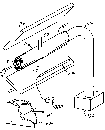
Fig. 1 is a partially schematic perspective view
of the invention.
Fig. 2 is a cross-sectional view, taken
perpendicular to a conduit axis, of a first embodiment.
_ g _
CA 02336476 2001-O1-02
wo ooioizaZ rcT~s99nsmo
Figs. 3a and 3b are an elevatianal and schematic
view of a second embodiment.
Fig. 4 is a schematic view of a third embodiment.
Fig. 5a is a plan view of a cylindrical reflector
inside a cylindrical-hemispherical tank;
Fig. Sb is an elevational view of the arrangement
of Fig. 5a;
Fig: 5c is a plan view of a meat container inside
the cylindrical reflector;
Fig. 5d is an elevational view of the container of
Fig. 5c;
Fig. 5e is an side view of a.n explosive strip; and
Fig.-5f is a frontal view of an. explosive strip.
Fig. &a is a plan view of tarok with moving
cylindrical reflectors; and
Fig. 6b is an elevational view of the arrangement
of Fig. 6a.
DETAILED DESCRIPTION OF THE PREFERRED EMBODIMENT
Here, and in the following t:laims:
"shock wave", "acoustic pul~~e", "pressure spike",
and similar terms, are used generally interchangeably. All
describe an acoustic wave or pressure wave travelling at (or
above) the speed of sound. The terms such as "shock wave"
also encompass high-energy square waves, sinusoidal waves,
and the like generated by loudspeaker:y and underwater
sirens. A sound having a frequency i:~ merely a repetition
of shock waves, and by Fourier's theorem a shock wave is
composed of frequencies. The present invention contemplates
treatment of food products by high-intensity sounds, whether
in discrete pulses or not; and
"conic section" has the usual mathematical
definitian: circles, ellipses, parabolas, and so on.
Fig. 1 shows the invention :Ln schematic and
theoretical overview. A food product P, which might k>e for
example deboned chicken parts in water as illustrated, or
instead a semi-solid cylinder of hamburger, i.e. a meat
slurry, moves through a plastic or other acoustically
_ 9 _
CA 02336476 2001-O1-02
WU 00101242 PCTIUS99/15110
transparent conduit 100 in the direction of large arrow A,
propelled by a mixer/pump 120 coupled to a feed pipe 110.
Water W, contained in a surrounding tank 400, surrounds the
conduit 100; for clarity, only a corner of the tank 400 is
depicted. The sectioned end of the conduit l00 is coupled
to another pipe (not shown) or other means to deliver the
food product P from the tank 400 for further processing.
As indicated above, the conduit 100 is preferably
made of a plastic or other material acoustically impedance
matched to water, the preferred liquid.. Inside the conduit
100 the food product, or mixture of food pieces and water,
is itself largely composed of water. Therefore the region
of the conduit 100 consists of either water or substances
which are acoustically similar to water and therefore this
region is substantially acoustically r~omogeneous. Shock
waves or sounds can pass across it with no great deflection
or reflection.
Adjacent the conduit 100 is a wave generator,
preferably an explosive device 200. I:t may be a chemical
explosive, e.g. in strip form, a set of spark electrodes, or
a mechanical device which produces a :hock wave or a sound
of sufficient comparable energy (e.g. a siren). The
explosive device 200 is coupled to a detonation circuit or
capacitive discharge release circuit 220 which controls the
timing of the explosion and also prov~_des energy for the
explosion in the case of electric-discharge or electro-
mechanical wave generation (e. g. it includes capacitor's).
Upon detonation or discharge. a shock wave expands
outwardly. One portion of the shock wave passes directly
through the conduit 100 as indicated by arrow S1: Other
portions of the shock wave, labeled S:? and S3, are reflected
from the shock-waves reflection surface, here represented by
baffles or reflectors Rl and R2, which in theory might. be
for example heavy spring-mounted stee:L plates, and pa~~s
through the conduit 100 as indicated by the corresponding
arrows. It is to be understood, howe~Ter, that this figure
does not show an important feature of the present invention,
- 10 -
CA 02336476 2001-O1-02
WO 00101242 PCT/U899/15110
namely the shock-reflective chamber having a conic section
which eliminates the need for springs or the like.
It will be seen that the paasage of the shock
waves S1, S2, and S3 can be made gene:rally simultaneous by
properly positioning the reflectors R:L and R2.
Alternatively, two shock wave generators 200 may be placed
symmetrically on either side of the conduit 100 (not shown
in Fig. 1); this arrangement also wil:1 provide for ba7.anced
impulses onto the conduit 100 when th~~ two generators 200
are both exploded simultaneously. Also, there could be
three wave generators spaced 120° apart, and so on:
Instead of water, any liquid (or even gas) may be
used to transmit the shock waves through the tank 400 and/or
to transport the food product P, in particular an aqueous
mixture of water and such substances as salts, pH adjusting
substances, disinfectants, surfactants, etc., can be used.
In this case the acoustic impedance of the conduit 100 may
be adjusted accordingly by appropriate selection of the
material from which the conduit is made.
It is noted that the liquid in the tank 400 may be
different from the liquid in the conduit 200. These two
liquids may have somewhat different acoustic impedances, but
these are preferably as close as possible. If the acoustic
impedances of the conduit 100, the first liquid, and the
~ second liquid are all generally similar, then shock wives
passing over the conduit will not be substantively diverted
(reflected or refracted) and the meat P inside the co:rzduit
100 will be treated as desired.
In its broadest but not preferred form, the
invention contemplates dropping food pieces or extruding
food vertically through water without. the use of a distinct
conduit. In such an arrangement the explosive device 200
and cylindrical reflector would be deployed about a vertical
axis instead of the conduit 100, i.e. the conduit would be
absent. However, such an embodiment requires careful and
difficult balancing of the shock wavea in opposing
- 11 -
CA 02336476 2001-O1-02
WO 00/01242 PCTIUS99/ISI10
_ directions to prevent the meat pieces from being blown
apart.
Fig. 2 is a cross section of a first preferred
embodiment taken on a plane perpendicular to the axis of the
tubular plastic conduit 100, which is filled with pieces of
food (e.g. chicken pieces, plastic film wrapped beef, or
hamburger) and liquid flowing in a direction into or out of
the plane of the paper. The conduit 1.00 is immersed in the
liquid 401 filling the tank 400, and this liquid 401 also
fills the annular space 302 of the cylinder 303 appearing in
the cross section of Fig. 2 as a generally football-shaped
opening. The cylinder 303 includes a generally concentric
cylindrical inner surface 307 of a heavy chamber:wall, and
two paraboloidal surfaces 301.
The explosive device in thi~~ embodiment includes
two pair of electrodes 201, each of the four electrodes
having a respective insulating sheath 203, each pair coupled
to a capacitive discharge device (not shown in Fig. 2) such
as disclosed in WO 98/54975 and a corresponding U.S. patent
application. The electrical parts exclusive of the
electrodes are kept dry by a watertight shield 205.
The spark gap of each pair of electrodes 201 is
geometrically centered on the focus of the surrounding
parabolic reflecting surface 301. The. two parabolic
reflecting surfaces (paraboloids of rESVOlution) share a
common axis, shown by a dash-dot line.
When a discharge takes placE= through either pair
of electrodes, the sudden release of <snergy creates a shock
wave followed by a gas bubble. The major portion of the
shock wave (in terms of spherical ang:Le) reflects off the
parabolic surface, creating a plane shock wave which
proceeds from the shock generator directly across the
cylindrical chamber, through the conduit 100 and the meat
therewithin, and onto the opposite parabolic reflector.,
which reflects the shock wave, for the second time, onto the
other pair of electrodes. The conver~~ing shock wave may
- 12 -
CA 02336476 2001-O1-02
WO 00101242 PCT/US99/15110
create a secondary local pressure rise from which the wave
may again radiate causing some back-anal-forth reverberation.
Other portions of the shock wave will bounce off
the cylindrical surface 307, and the meat, water and conduit
100 will to some extent refract the shock wave. As a result
of the multiple reflections and refractions, the shock wave
will reverberate inside the cavity, causing a quasi-
hydrostatic pressure rise. Both pairs; of electrodes 201 are
desirably discharged simultaneously, dLoubling the energy
imparted to the food product and preventing any net
imbalance of force on the conduit from the shock wave 9r
subsequent gas bubble.
The cylindrical surface 307 is preferably
approximately as long as its diameter and the ends of the
explosion containment cylinder 303 (bounded by the
cylindrical surface 307) are preferably open to permit water
to be blown out of the ends by the force of the gas bubble
created by the explosion (i.e. the wat:er moves into and out
of the plane of the paper). The explosion is radially
contained by the strong cylinder wall:>, which are preferably
made of stainless steel. Because of t:he cylindrical
symmetry, the impulse imparted to the meat is balanced., and
there is no net force tending to blow the meat, or the
conduit, away from its central location as long as the
explosions are simultaneous and of equal energy. If only
one of the shock generators creates a shock wave, then. there
may be a sideways force on the conduit: 100, depending on the
hydrodynamics after the explosion, anti especially the gas
bubble which quickly follows the shock wave.
After the explosion, water X601 within the tank 400
will immediately flow back to fill the cavity 302
surrounding the conduit 1.OO, in time for the next explosion
that will treat the meat yet to arrive at the shock wane
zone between the parabolic reflectors. The continuously
moving food product is treated continuously by the continual
repeated explosions at the electrodes creating shock waves
inside the reverberant cavity.
_ ~3 _
CA 02336476 2001-O1-02
WO 00/01242 PCT/US99/15110
Alternative embodiments to that of Fig. 2 (not
shown) include various placements of the electrodes and
their parabolic reflectors. Instead of the two
diametrically opposed shock generators spaced 180° apart
shown in Fig. 2, three shock generators spaced 120° apart
can be used, four spaced 90° apart, and so on. The shock
generators can also be staggered along the axis in sets, and
so on. The axially spaced explosions may be simultaneous or
sequential.
Fig. 3a shows a second embodiment in which anly
one shock generator is used but in which the shock waves hit
the conduit from opposite directions, creating a balanoed
force and a quasi-hydrostatic pressure: rise. Mounted inside
the tank 400 are an explosion chamber 210, a treatment
chamber 310, and a toroidal pipe 230 a;upported on across
member 402. As in Fig. 2, the conduit: 100 is perpendicular
to the plane of the paper. The ends of both halves of the
toroidal pipe 230 are coupled into both the explosion
chamber 210 and the treatment chamber 310, so that the water
inside can flow clockwise or counterc~_ockwise as seen in
Fig. 3a. The schematic cut-away Fig. 3b shows how the
sections of the toroidal pipe 230 connect with the treatment
chamber 310.
A discharge wire 207 is seen passing from outside
to the explosion chamber 210 in Fig. 3a. An explosion.
inside the explosion chamber 210 creates shock waves which
travel along the inside of the toroid<~l pipe, bouncing off
the reflective curved surfaces of the pipe 230 as they
progress, and reaching the treatment chamber simultaneously
because of the equal lengths of the two sections of the
toroidal pipe coupling the explosion <~hamber 210 to tYae
treatment chamber 310.
The balanced shock wave imp<~ct from opposite sides
prevents sideways force on the shock-'Nave transparent and
meat containing conduit 100, and the use of a single shock
generator obviates the need for synchronizing two or more
shock generators at any single axial :location.
- 14 -
CA 02336476 2001-O1-02
WO 00/01242 PCT/US99/15110
_ The present invention includes the use of more
than two pipes to convey shock pulses in balanced fashion to
the treatment chamber 310. Any number greater than two can
be used, and if of equal length can be: of any shape.
Fig. 4 depicts a third embodiment of the present
invention. Here the cylindrical surface 307 of Fig. 2 is
flattened into a chamber having a surface 307' with an
elliptical cross section. At one focus of the ellipse is
the electrode pair 201 and centered at: the other focus is
the meat containing conduit 100. A geometrical property of
the ellipse is that rays from one focus, internally
reflected from the inner wall of the elliptical chamber
307', converge at the other focus. BE:cause of this
property, the shock wave from the elecarode 201 will
converge onto conduit 100 from all sides and impinge a.t all
points on the conduit surface simultaneously, except that
the shock wave coming directly from the electrode 201 will
pass through the conduit 100 before the arrival of the, rest
of the shock front, bounce off the far wall, and then hit
the conduit again at the same time as the rest of the shock
front reaches the outside of the conduit.
If the explosion comes from a point, as from a
pair of electrodes like those of Fig. 2, then the shock wave
will not converge precisely on the center of the conduit,
except directly opposite the explosion. The convergence at
other locations along the conduit wil:1 not be precise7_y
centered. If the shock wave comes from a line explosion
(e.g., a strip of explosive in the same position as the
electrode of Fig. 4) the shock wave will impinge on the
conduit 100 simultaneously and uniformly along its length
corresponding to the length of the strip explosive.
The same convergence of shock waves onto the
conduit which is exhibited by the elliptical shape of Fig. 4
can be achieved with refractive acoustic lenses. Such a
lens (not shown) can be made by immersing in the tank 400 a
hollow air-filled shell shaped like an optical converging
lens. In the case of a conduit or container made at :Least
- 15 -
CA 02336476 2001-O1-02
WO OO/OI242 PCTIUS99/15110
_ partially of materials less than perfectly impedance-matched
to the surraunding liquid, the conduit: or container wall (or
some portion of it) can act as a lens to control the
convergence and/or divergence of the waves in the liquid
inside and outside the container/conduit.
Two further alternative and preferred embodiments
are schematically illustrated in Figs.. 5a-5f and 6a-6b.
Figs 5a-5f illustrate a static or batch system and Figs. 6a
and 6b illustrate a continuous or semi-continuous
(intermittent) system involving a conveyor. Both
embodiments as illustrated use chemical explosive strips 520
placed against the inside wall of a shock-wave reflective
steel cylinder 530 with an inner cylindrical surface 307"
acting as a reflector. Both systems can also be adapted to
use electrical discharge explosion in place of the explosive
strip 520 (not shown in Figs. 5a-5f).
The explosive strips 520 are preferably adhered to
metal straps 522 having upper hooks 5:Z3 which hook over the
upper edge of the shock-wave reflective cylinder 530. The
chemical explosive strips 520 preferably used in the
illustrated embodiment have a sticky backing. This
explosive is commercially available in sheets and can be cut
into strips which are then placed on the metal straps 522
that hang from the upper edge of the cylinder 530. The
straps 522 can be installed in a matter of seconds alang the
interior of the cylinder. The strips 522 survive the
explosion and can be used repeatedly.
A preferred embodiment of t:he cylinder .530 i.s
open-ended, made of stainless steel, 'with a wall 2 inches (5
cm) thick, 2& inches (66 cm) long on the axis and with an
inside diameter of 52 inches (132 cm). Lifting eyes ~>31 may
be provided along the upper edge of t:he cylinder 530.
In the embodiment illustrated in Figs Sa-5f, the
meat is placed in a cylindrical container 500 (shown in
Figs. 5c and 5d) having a body 502 and a tight lid 507_ held
in place thereon, such as by frictional forces or retaining
means of various types, and preferably the container 500 is
- 16 -
CA 02336476 2001-O1-02
WO 00101242 PCTlUS99/15110
_ made of plastic material.,.e.g. TYGON, having an acoustic
_ impedance close to that of water. The container 500 thus
corresponds to the conduit 100 of the earlier described
embodiments. The lid 501 preferably has a check or burp
valve to permit escape of liquid when the container 500 is
squeezed by the gas bubble. The diameter of the container
500 is preferably smaller than the radius of the open-ended
stainless steel cylinder 530 by about 8 inches (20 cm),
resulting in a four-inch (10 cm) annulus between the
container 500 and the reflective cylinder wall 307" of the
cylinder 530. In experiments conducted, the container 500
was a commercially available RUBBERMAID garbage can formed
of plasticized vinyl plastic.
Figs. 5a and 5b show an optional basket 450, which
may be made of quarter-inch (0.6 cm diameter) stainless
steel rod with openings about 4 inches. (10 cm) square. In
an embodiment which is not preferred, the basket 450 may be
used to support and retain the plastic' container 500, and
may itself be supported on a support 454. In yet another
embodiment, the container 500 may be eliminated and the meat
packed directly in the basket 450, but, this also is not
preferred for reasons given above.
The entire assembly, submerged in water within the
tank 400, may rest on the tank bottom which may have a
generally hemispherical shape as shown in Fig. 5b, although
the shape of the tank 400 is irrelevant. The container 500,
and/or the basket 450 and support 454, can be placed into
the hemispherical tank or other water containing structure
by a crane (not shown). Other types of supports can be used
in place of the support 454.
In Fig. 5b, the cylinder 530 is spaced about 12
inches (30 cm) from the hemispherical bottom of the tank
400. This space is sufficiently large to permit the gas
bubble to vent without moving the cyl:~nder 530.
As indicated above, it is preferred to use a
closed container alone with a suitable support to hold it in
position, without the open basket 450.. Such a container
- 17 -
CA 02336476 2001-O1-02
WO 00/01242 PCT/US99/15110
500, as discussed above, is preferably a water-tight
_ container formed of a material which i;s an acoustic match
with water, e.g. plasticized vinyl plastic, filled with meat
and then filled with the inert or meat-treating liquid, e.g.
water or water containing additives.
The strip chemical explosive 520 is placed at 90°
locations around and along the inner wall 307" of the
cylinder 530 as best shown in Fig. 5a. and extends the
height (length} of the cylinder. However, the length,
thickness, width and positioning of the explosive strips can
be varied. It has been found that when the explosive is
detonated at a distance as close as four inches from the
bagged meat packed within the container 500, neither burn
nor rupture of the bag around the meat occurs. The result
on some tougher cuts of meat subjected to this treatment has
been a 50o improvement in tenderization over the use of
earlier embodiments in which the meat is placed against or
closely adjacent the hemispherical wall of the tank 400.
The present invention and especially the
embodiments of Figs. 5a-5f and 6a-6b have a number of
advantages as compared to the previous methods and
apparatus.
(1) All of the energy of the explosion is
directed inwardly toward the meat so that substantially all
of the energy of the explosion acts on the meat to effect
its tenderization and/or destruction of microorganisms on or
in the meat. In the absence of the cylinder 530, 303, 310,
e.g. in the use of the hemispherical tank 400 with the
explosive discharge occurring at the focus of the
hemisphere, half of the energy is directed upwardly causing
displacement of water from the tank, whereas only the other
half is directed downwardly and outwardly toward the meat.
With the strip explosive, for example, the energy from the
explosive which would otherwise be directed radially
outwardly is reflected back inwardly by the cylinder wall in
the same direction as the remainder of the explosive
discharge. Theoretically, half as much strip explosive
_ 18 -
CA 02336476 2001-O1-02
WO 00101242 PCT/US99/15110
_ should be needed, compared to the amount used when the meat
_ is placed along or adjacent to the hemisphere and the
explosive discharge is carried out at the focal point as per
prior embodiments.
(2) Packing the meat in a cylindrical shape
within the container 500 of the embodiments of Figs. 5a-5f
and 6a-6b simplifies handling of the meat and fabrication of
the container, either in open basket form or from a material
that is an acoustic match with water. One problem in
earlier embodiments was the failure of: the meat wrapping
material which sometimes failed as a result of exposure to
either the shock wave or the gas bubble. Because the bag
- meat in earlier embodiments was in the: same water that was
exposed to the explosive discharge, in the case of bag
failure some water would come in directs contact: with the
meat, and that water contained chemicals resulting from the
explosion, possibly tainting the meat.
Use of a water impervious container 500 containing
the meat and potable water in accordance with present
invention solves this problem. For ea~ample, if a
cylindrical container in which the meat is loaded is filled
with potable water and sealed, the meat cannot come into
contact with the water outside the container even if a meat
packaging bag experienced a rupture. The same is true with
respect to the continuous movement embodiments of Figs. 2-4.
(3) Using a shock-wave ref:Lective cylinder,
especially with strips of explosive p:Laced vertically
against the inside wall of the cylinder as in Figs. 5a-5f
and 5a-6b, produces balanced forces o:E detonation. Shock
waves, reflected inside the cylinder, produce hoop stress
within the cylinder, but the forces a:re balanced and t:he
cylinder does not move as a result of the explosion. The
same effect is achieved by properly-p:Laced electrodes, for
example within cavities along the interior wall of the
cylinder (not illustrated). The forces are similarly
balanced in the embodiments of Figs. :2-4.
- 19 -
CA 02336476 2001-O1-02
WO 00/01242 PCT/US99/15110
_ The hydrodynamics of the present system produce
shock waves that propagate from the shock-wave reflective
cylinder wall and collide in the meat packed within the
basket. This produces a pressure doubling, and an
successive reflections produces a quasi hydrostatic pressure
environment which lasts for more than 100 microseconds.
Except in the special embodiment of Fig. 4, the interior
wall of the shock-wave reflective cylinder must be spaced
closely adjacent the basket to produce this effect since the
wall acts as a reflector and contains the colliding shock
waves.
The use of a water-impervious inner basket
containing potable water along with th:e meat provides
another advantage in that it allows the meat to be wrapped
in a less expensive wrapping. If the shock wave generated
by the explosion causes any tear or rapture in the plastic
wrapping, the meat will not be harmed in any event because
it is surrounded by potable water.
Figs. 6a-6b show a related embodiment in which
preferably the same cylinder 530 as i~> in the embodiment of
Figs. 5a-5f is used, but with trunnions 532 or the like and
other minor modifications. The two open ends of the heavy-
duty shock-wave reflective cylinder 5_90 again produce a
balanced force so that the cylinder 530 does not move as a
result of the explosion, because the c~as bubble exhausts
with equal force from both open ends of the cylinder.
The embodiment of Figs. 6a and 6b uses a conveyor
or track 650, shown schematically, for continuous or
intermittent (semi- continuous) operation. The conveyor 650
may be, for example, a set of continuous belts running on
rollers and having indentations for the trunnions 532 of the
cylinder 530. The meat P is packed within the container 500
as in the other embodiment of Figs. 5a-5f, centered within
the steel cylinder 530.
Figs. 6a and 6b show an elongated tank 400,
preferably of 3/4-inch (2 cm} thick stainless steel embedded
in concrete. This elongated and simplified tank provides an
- 20 -
CA 02336476 2001-O1-02
WO 00101242 PCTIUS99/15110
_ improvement over the embodiment of Fic~s 5a-5d..as
illustrated, due to the high cost of t=he hemispherical tank
and its supporting structure, which can weigh many tons.
The tank 400 of Figs 6a-6b can be quit=e large, e.g. 14 ft.
long, 8 ft. wide and 8 ft. deep. A bubble curtain may be
placed around the sides of the tank 4C10.
The large size of the tank 9600 tends to reduce the
reaction of its walls to both the shot:k wave and the gas
bubble. However, additional shock ab:>orbing structures are
desirably included. For example, bene=ath the location of
the cylinder 530 at which the explosive discharge is to take
place, a steel plate 672 is located at: a distance of about 3
feet (0.9 m) from the bottom of the cylinder. This steel
plate 672 is for example 6 ft (1.8 m) in diameter and 3
inches (8 cm) thick. The steel plate 672 is supported. by
springs 674, desirably Belleville spr_i.ngs, an the tank
bottom. Dashpots 676 axe also preferably provided, which
act as shock absorbers to mitigate thEa downward force of the
shock wave and gas bubble. The sprin<~s 674 return the plate
to its previous position after deform<~tion caused by the
explosion.
The energy from the upwardly forced water is
absorbed by a hood or explosion shield 671 located above the
tank. The hood is desirably not attached to the tank itself
because of the upward kinetic energy :in the water, a result
of the expanding gas bubble.
In operation, the container 500 filled with water
and meat is placed into the heavy-duty cylinder 530 by
arrangements such as those of Figs. 5;a-5f, probably with the
use of a crane 632 due to the substantial weight invo7_ved.
The cylinder 530 is engaged to the co=nveyor 650, which moves
the cylinder 530 to the explosion position under the hood
and below the water level. After explosive discharge,. the
cylinder 530 is maved again, preferably to the opposite end
of the tank where it is removed by a crane 632. While: this
is occurring, another cylinder is lowered into the tank and
moved into position for firing. (Alternately, the cylinder
- 21 -
CA 02336476 2001-O1-02
WO 00/01242 PCT/US99/15110
_ 530 is carried in a circular.path.so .as to return to its
starting point. Also, it can be arranged to obviate the
need to stop at the firing point.)
With such a continuous or semi-continuous system,
it is estimated that at least twice as much product can be
tenderized in the same amount of time as with earlier
embodiments in which the meat is placed along or closely
adjacent the surface of the hemispherical tank.
Because the system Figs 6a-6b does not utilize the
1~ hemispherical-bottom tank illustrated in Figs 5a-5F, t:.he
cost of the system is substantially reduced.
In the following claims, an acoustic impedance of
a conduit material is "similar" to the acoustic impedance of
the surrounding liquid if a shock wave impinging on the
conduit is refracted or reflected at the surfaces of the
conduit to such a small extent that food products in liquid
inside the conduit are subjected to a sufficient shock wave
intensity, in spite of such refraction or reflection, to
tenderize and/or sterilize the food product.
It is noted that the acoustic impedance of the
conduit wall may be partly a function of wall thickness or
structure (e.g. porosity). A shock wave may pass through a
very thin layer of steel which would substantially re:~lect
the shock wave if the steel were thicker. Thus materials
having an acoustic impedance less closely matched to that of
the liquids can be used in the present invention depending
on geometry.
Because the speed of a shock wave can vary with
intensity, and intensity can vary with distance from 'the
shock wave generator (chemical charge or electrode), 'the
present invention contemplates adjusting the path distance
from the explosion to the conduit (including any reflections
or refractions) to account for such variations. Also, when
the invention employs refraction (i.e.. acoustic lensi;ng) to
divert shock waves onto the conduit; the delay in transit
time from the explosion to the conduit will take into
account the different speed of the shock wave within the
- 22 -
CA 02336476 2001-O1-02
WO 00/01242 PCT/US99/15110
refractive medium. For example, an air-filled bladder
inside a liquid can change the angle of a shock wave and by
suitably shaping the bladder the shock wave can be refracted
onto the conduit; but the shock wave will be slowed while in
the air and arrive later than if it had passed through
liquid.
The foregoing description of the specific
embodiments will ~so fully reveal the general nature of the
invention that others can, by applying current knowledge,
readily modify and/or adapt for various applications such
specific embodiments without undue experimentation and
without departing from the generic concept, and, therefore,
such adaptations and modifications should and are intended
to be comprehended within the meaning and range of
equivalents of the disclosed embodiments. It is to be
understood that the phraseology or terminology employed
herein is for the purpose of description and not of
limitation. The means and materials for carrying out
various disclosed functions may take a variety of
alternative forms without departing from the invention.
The terms "cylinder" and "generally cylindrical
configuration" are not to be taken to specify a precise
circular cylinder. Thus, the conduit or container, as well
as the leavy-duty shock-wave reflective container or
cylinder, can have for example an octagonal cross-section.
The expressions "means to..." and "means for..."
as may be found in the specification above and/or in the
claims below, followed by a functional statement, are
intended to define and cover whatever structural, physical,
chemical or electrical element or structure may now or in
the future exist which carries out the recited function,
whether or not precisely equivalent to~ the embodiment or
embodiments disclosed in the specification above; and it is
intended that such expressions be given their broadest
interpretation.
- 23 -