Note: Descriptions are shown in the official language in which they were submitted.
CA 02336502 2001-02-14
PUSH BACK STORAGE RACK SYSTEM
BACKGROUND OF THE INVENTION
The present invention is directed to the field of storage rack systems. More
particularly, the
present invention is directed to a push back type of storage rack system for
storing a plurality of loads
in which multiple loads may be stored in a single storage lane.
Push back storage racks normally comprise an assembly of shelves and vertical
uprights for
supporting loads placed on tracks or other base members in one or more storage
lanes. Each storage
lane has one loading position capable of storing one load. One or more
vertically spaced push back
carts are positioned in the loading position. Each cart is capable of
receiving one load, being pushed
toward the back of the lane by the next load, and sliding over the top of one
another when unloaded.
Such systems normally have their tracks in each lane tilted toward the loading
position so that the force
of gravity causes the next cart in line to return to the loading position when
a load occupying the
position is removed.
When adding a load to a particular lane, the operator pushes the added load
against a
previously stored load occupying the lane's loading position. This forces the
cart under the previously
stored load further up the lane and out of the loading position, thereby
making room for the load being
added. If additional carts are in the loading position, the operator then
positions the load on the next
available cart. If all the carts have been pushed out of the loading position,
the added load fills the
lane to capacity, and the operator places the added load directly onto the
tracks or base member of the
lane itself.
Previous push back storage systems have also included designs which permit
unloaded carts
to automatically slide into the loading position of their respective storage
lanes to receive loads. Most
CA 02336502 2001-02-14
designs allow the empty carts to simultaneously occupy the same loading
position by incorporating
either a nesting or telescoping cart arrangement.
In previous nesting designs, higher level carts retract or nest within the
horizontal dimensions
of each next lower level cart. Such designs have been limited in both the
number of carts that can be
included in a single system and in the relative strength of each cart since
the designs typically require
the use of a single pair of track members and since the required horizontal
clearance for successive
carts prevents the inclusion of structural cross members. Due to the resulting
limitations on the
amounts of available space in such designs, these characteristics have also
severely limited the
number of carts that can be used and thus the number of loads that can be
stored in a single lane.
Additionally, smaller and weaker components may be used which substantially
reduce the load-
bearing capabilities of the system. In addition to substantially limiting the
system's load-bearing
capacity, smaller components, such as cart wheels, also tend to increase the
amount of external force
necessary to operate such systems. This ultimately leads to the need for more
steeply sloped track
inclines, which are undesirable, and normally increases the amount of wear and
potential damage to
the system, loading equipment, and stored loads.
In previous telescoping designs, individual carts have been vertically spaced
so that each
higher level cart merely slides over the top ofthe next adjacent lower level
cart. Previous telescoping
designs have been severely limited in the number of carts that can be
incorporated in a single lane due
to the vertical space needed to include a rigid support piece across the width
of each cart. Such cross
pieces tend to make the additional vertical height required for each cart too
great to incorporate many
carts into a single lane. In contrast, eliminating such pieces tends to
severely reduce the load capacity
of each individual cart.
-2-
CA 02336502 2001-02-14
Previous telescoping designs have also been limited by the fact that most use
only a single pair
of track members with one or more support surfaces upon which the wheels of
the various carts ride.
As with nesting designs, this characteristic of most telescoping designs has
severely limited the
number of carts and thus the number of loads which can be included in a single
lane, while posing
the same problems of wear, potential damage to the system, equipment, and
loads. In the few
instances where multiple pairs of tracks have been incorporated, some portions
of the various support
surfaces have been left unused. As a result, both space and load-bearing
capacities have been wasted
in such previous systems, reducing their cost-effectiveness and versatility.
In some previous designs, push plates have been positioned at the trailing
edge of the lowest
or last-loaded cart to assure that an operator maintains proper pallet
clearance during loading and to
indicate, when it is not visible to the operator, that a particular lane is
filled to capacity. It has been
observed from time to time that pallets on which loads are stored drag against
an adjacent surface of
the push plate, causing damage to the pallets during loading and unloading.
Many of the previous designs of push back rack systems have also been plagued
by the
problem of outward bowing of the beam adjacent each lane's loading position.
The problem is
associated with the repeated forces exerted by a system's carts as they
automatically return to their
respective loading positions. As each cart repeatedly returns to this
position, stopping forces are
exerted upon the adj acent beam member which, over time, tends to bend or warp
outwardly and away
from the storage lane in which it is mounted. This is an additional problem
which previous push back
storage systems have yet been unsuccessful in resolving.
-3-
CA 02336502 2001-02-14
BRIEF SUMMARY OF THE INVENTION
The present invention is a push back storage rack system for storing a
plurality of pallet loads
in which multiple loads may be stored in a single storage lane. Each lane
contains at least two
wheeled carts, each cart being capable of receiving and storing multiple
pallet loads. The carts are
vertically spaced so that they can freely slide underneath each other when
unloaded. Beginning with
the first or lowest level cart in the system, each successively higher cart is
also wider and longer than
the cart immediately beneath it. The carts are positioned on at least one but
potentially two pairs of
rectangular tracks or tubes, each tube being capable of supporting two or four
individual carts,
depending on how the carts are constructed and installed on the tubes. The
tubes are mounted on an
incline away from a loading end of each lane so that when loads are placed on
and removed from a
lane, the carts are biased toward the loading end of the lane by the force of
gravity. Each tube has a
single, planar upper support surface which has inside and outside edges. The
wheels of each cart ride
only on either the inside or outside edges of the tubes on which they are
mounted, allowing more than
one vertically spaced cart to occupy the same tube. A support beam is located
at the loading end of
each lane.
The end of each cart closest to the loading end of the lane in which the cart
is mounted is the
trailing end of the cart and the opposite end of each cart is the leading end.
When the carts are
unloaded and positioned in a loading position at the loading end, the trailing
end of the lowest cart
rests flush against the adjacent support beam. The carts are constructed so
that each successively
higher cart is slightly longer than the next cart below. Following the lowest
level cart of the system,
a structural member at about the leading end of each successively higher cart
contacts a structural
member at about the leading end of the cart immediately below it when
returning to the loading
position. This transfers the impact force of each load to the trailing end of
the lowest cart, thereby
-4-
CA 02336502 2001-02-14
minimizing curling and excessive warping of the beam. Additionally, tension
bars positioned
between approximately the middle of the structural beam and other structural
members of the rack
system also serve to significantly reduce the bowing or warping effect to a
minimum. A push plate
mounted on the trailing end of the lowest cart is offset from vertical, away
from this cart, to prevent
dragging on the end of pallets and subsequent damage to individual pallets and
loads.
In the preferred embodiment of this invention the structural member at the
leading end of each
cart is an angle plate having two sections at a 90° angle to one
another. The fact that each successively
higher cart is slightly longer than the next lower cart enables the end of
each cart's horizontal section
to contact the vertical section of the cart beneath it so that the carts stack
above one another without
greatly adding to the vertical height needed for each additional cart.
Additionally, the vertical section
of each leading angle piece provides rigidity for supporting heavy loads.
At the trailing edge of each cart, relatively thin loading plates can also
stack without adding
a great deal of vertical height to the system. To maintain rigidity, vertical
stiffeners extend downward
below each loading plate, substantially along the width of the cart. For each
successively higher cart,
the stiffener is placed slightly further away from the cart's trailing edge
than the stiffener on the cart
immediately beneath it, allowing the stiffeners to remain clear of each other
when the carts are
stacked in the loading position.
In an optional embodiment of the design, up to four additional carts may be
included in the
system. In this embodiment, the wheels of every second adjacently spaced pair
of carts travel along
the same edges of a particular pair of tubes, the two adjacent carts being
interlocked by having the
trailing wheels of one cart positioned between the leading and trailing wheels
of the other. Thus, it
becomes possible to position twice the number of carts on the same number of
tubes without
consuming substantial additional space.
-5-
CA 02336502 2001-02-14
The narrow stacking characteristics inherent in this novel design enable as
many as nine loads
to be positioned in a single storage lane. Each individual cart, up to a
maximum of eight, can store
one load. A ninth load can then be positioned directly on the storage lane's
tubes after all of the carts
are loaded. For applications requiring the storage of five or fewer loads per
lane, minor modifications
to the design enable the system to be even more compact. The use of multiple
rails and interlocked
carts enable heavier components, such as wider and higher capacity wheels, to
be incorporated into
the design. Such components require less external force for operation,
allowing for a gentler inclined
slope for the inclined tubes and a higher load capacity for the individual
carts, thereby reducing the
amount of wear and potential damage experienced by the system, stored loads,
and loading
equipment.
Other embodiments of the invention include mechanisms for preventing
accidental lifting or
disengagement from the tubes without increasing the sizes of successive carts.
In one embodiment,
wheels from the one or two carts positioned on the inside edges of the outer
tubes are positioned to
extend toward the carts' middle portions in order to provide clearance for
vertical anti-lift extensions
that reach downwardly from the carts on the outside edges of the inside tubes.
The inner carts, in
turn, have horizontal flanges which prevent vertical movement of the outer
carts. In another
embodiment, the system's lowest and highest carts dispose vertical extensions
which lock the carts
to stop flanges located below the inside edges of the inside tubes and below
the outside edges of the
outside tubes, respectively. A series of interlocked flanges positioned
between the individual carts
then works as an integrated mechanism to prevent vertical movement of the
carts. Both of these
embodiments save additional space and enable the incremental spacing of
successive carts to remain
substantially constant regardless of the particular tube or edge on which the
cart's wheels are
positioned.
-6-
CA 02336502 2001-02-14
Various other features, advantages, and characteristics of the present
invention will become
apparent to one of ordinary skill in the art while reading the following
specification. This invention
does not reside in any one of the features of the push back rack system
disclosed below. Rather, this
invention is distinguished from the prior art by its particular combination of
features which are
disclosed. Important features of this invention have been described below and
shown in the drawings
to illustrate the best mode contemplated to date for carrying out this
invention.
Those skilled in the art will realize that this invention is capable of
embodiments which are
different from those shown and described below and that the details of the
structure of this push back
rack system can be changed in various manners without departing from the scope
of this invention.
Accordingly, the drawings and description below are to be regarded as
illustrative in nature and are
not to restrict the scope of this invention. The claims are to be regarded as
including such equivalent
push back rack systems as do not depart from the spirit and scope of the
invention.
IN THE DRAWINGS
For a more complete understanding and appreciation of this invention and many
of its
advantages, reference should be made to the following, detailed description
taken in conjunction with
the accompanying drawings wherein:
FIG. 1 is a perspective view of a push back storage rack system according to
the invention
illustrating the relative positioning of carts and loads in multiple
independently operating lanes
positioned throughout the system;
FIG. 2 is a side view of the push back storage rack system of FIG. 1, further
demonstrating
the relative inclines of the individual vertically spaced storage lanes;
CA 02336502 2001-02-14
FIG. 3 is a perspective view of an independent push back storage system as
would typically
occupy one cart lane having four individual and unloaded carts as if
positioned at the loading end of
a particular lane;
FIG. 4 is a front view of two adjacent tubes from the push back storage system
of FIG. 3
depicting the respective wheels, angle plates, and hold-down cart components
positioned adjacent to
the depicted tubes;
FIG. 5 is an exploded view of the push back storage system of FIG. 3 depicting
the structural
details of the individual carts of the system;
FIG. 6 is perspective view of an independent push back storage system as would
typically
occupy one cart lane having five individual and unloaded carts as if
positioned at the loading end of
a particular lane;
FIG. 7 is a front view of two adjacent tubes from the push back storage system
of FIG. 6
depicting the respective wheels, angle plates, and hold-down cart components
positioned adjacent to
the depicted tubes;
FIG. 8 is an exploded view of the push back storage system of FIG. 6 depicting
the structural
details of the individual carts of the system;
FIG. 9 is a side view of the trailing edges of the carts of the push back
storage system of FIG.
3 depicting the loading plates and stiffeners of the individual carts.
FIG. 10 is a side view of the leading edges of the carts of the push back
storage system of FIG.
3 depicting the leading angle plates of the individual carts; and
FIG. 11 is a side view of an alternate embodiment of the leading edges of the
carts of the push
back storage system that is the subject of the invention depicting the leading
angle plates of the
individual carts.
_g_
CA 02336502 2001-02-14
DESCRIPTION OF A SPECIFIC EMBODIMENT
Refernng to the drawings, identical reference numerals and letters designate
the same or
corresponding parts throughout the several figures shown in the drawings.
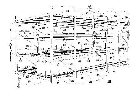
FIG. 1 shows a push back storage rack system of the type that is the subject
matter of the
invention. The system is based on a storage rack assembly 20 comprising a
number of interconnected,
vertical uprights 22 and horizontal beams 24. Side horizontals 26 and diagonal
cross pieces 28 may
also extend between the vertical uprights 22 to make up rack cells 30 along
the depth of the rack
system. Two separate cart lanes 34, each having a load end 32, are positioned
along the lengths of the
beams 24. To prevent the beams 24 from bowing outwardly and away from the rest
of the system due
to the stresses exerted on the beams 24 during operation, one or more diagonal
tension bars 36 may
also be positioned between about the center of one or more of the beams 24 and
one or more vertical
uprights 22 under the cart lanes 34. Alternatively, diagonal tension bars may
be fastened between
about the center of a beam 24 and a beam at the end of the first rack cell 30
that is connected to the
uprights 22 at the end of that rack cell. As shown in FIG. 1, a separate push
back assembly occupies
each individual lane 34.
Referring briefly to FIG. 2 along with FIG. 1, the storage rack assembly 20 is
capable of
storing multiple loads 38 in each cart lane 34. Each load 38 is placed on a
separate cart that rides on
a set of tracks which are mounted at a slight incline away from the loading
end 32 of the cart lane 34.
First, second, third, and fourth carts 41, 42, 43, and 44 are shown in an
extended position in three
vertically stacked cart lanes 34 on tracks which comprise a pair of tubes 50
that extend along their
respective cart lane 34.
-9-
CA 02336502 2001-02-14
The four-cart configuration of the carts 41-44 is depicted in its unloaded
position in FIGS. 3
and 4. The pair of tubes 50 includes a pair of parallel inside tubes 52 and a
pair of parallel outside
tubes 54. Each of the inside tubes 52 has a single upper support surface 56
having an inside edge 58
and an outside edge 60. In this embodiment, each outside tube 54 is
substantially similar to each
inside tube 52, with the outside tubes 54 also each having a single upper
support surface 55, an inside
edge 57 and an outside edge 59.
As shown in FIG. 5, the first cart 41 has a pair of parallel side angle plates
62 with each angle
plate 62 having a substantially horizontally planar surface 64 and a
substantially vertically planar
surface 66. The horizontal surface 64 extends outwardly from the vertical
surface 66 and away from
the middle of the first cart 41. Each vertical surface 66 has at least two
cart wheels 68 mounted on
it which are positioned to ride directly on the inside edge 58 of the upper
support surface 56 of the
inside tube 52 on which they are mounted. The first cart's wheels 68 also
extend outwardly and away
from the middle of the first cart 41. Each wheel 68 has a flanged edge 70 for
engaging the inside
edges 58 of the tubes 52 and for properly positioning the wheels 68.
Each cart has a leading end which is the end that is farthest from the loading
end 32 of the cart
lane 34 in which it is located and has a trailing end which is farthest from
the loading end 32.
Referring again to FIG. 5, a structural member shown as a leading angle plate
72 extends between the
side angle plates 62 at the leading end of the first cart 41. Like the side
angle plates 62, the leading
angle plate 72 has a substantially vertically planar surface 74 and a
substantially horizontally planar
surface 76 forming the cart's leading end 78. A trailing connecting tube 80
also extends between the
side angle plates 62 forming a trailing end 82 of the cart 41.
A push plate 81 is mounted at the cart's trailing end 82. Though having a
substantially
vertically planar lower surface 85, the push plate 81 has an upper portion 83
that is bent slightly, for
-10-
CA 02336502 2001-02-14
example five degrees away from vertical, leaning away from the first cart 41.
The functional
advantages of this feature are examined more closely below.
Referring back to FIG. 4, the second cart 42 rides on the outside edges 60 of
the upper support
surfaces 56 of the inside tubes 52. The second cart 42 has a pair of parallel
side angle plates 84 with
each angle plate 84 having a substantially vertically planar surface 86 and a
substantially horizontally
planar surface 88. The horizontal surface 88 extends inwardly from the
vertical surface 86 and toward
the middle of the second cart 42. Each vertical surface 86 also has at least
two cart wheels 90
mounted on it which are positioned to ride directly on the outside edge 60 of
the inside tube 52 on
which they are mounted. The second cart's wheels 90 also extend inwardly and
toward the middle
of the second cart 42. Each wheel 90 has a flanged edge 92 for properly
positioning the wheels 90
and for engaging the outside edges 60 of the tubes 52.
As best shown in FIG. 5, a structural member shown as a leading angle plate 94
extends
between the side angle plates 84 of the second cart 42. The leading angle
plate 94 also has a
substantially vertically planar surface 96 and a substantially horizontally
planar surface 98 forming
the cart's leading end 99. A trailing loading plate 100 extends between the
side angle plates 84
forming the trailing end of the second cart 102.
Referring again to FIG. 4, the third cart 43 rides on the inside edges 57 of
the upper support
surfaces 55 of the outside tubes 54. The third cart 43 has a pair of parallel
side angle plates 104 with
each angle plate 104 having a substantially vertically planar surface 106 and
a substantially
horizontally planar surface 108. The horizontal surface 108 extends inwardly
from the vertical
surface 106 and toward the middle of the third cart 43. Each vertical surface
106 also has at least two
cart wheels 110 mounted on it which are positioned to ride directly on the
inside edge 52 of their
respective outside tube 54. The third cart's wheels 110 also extend inwardly
and toward the middle
-11-
CA 02336502 2001-02-14
of the third cart 43. Each wheel 110 has a flanged edge 112 for engaging the
inside edges 57 of the
tubes 54 and for properly positioning the wheels 110 on these tubes.
Again as best shown in FIG. 5, a structural member shown as a leading angle
plate 114
extends between the side angle plates 104 of the third cart 43. The leading
angle plate 114 also has
a substantially vertically planar first surface 116 and a substantially
horizontally planar second surface
118 forming the cart's leading end 119. Like the second cart 42 and unlike the
first cart 41, a trailing
loading plate 120 extends between the side angle plates 104 forming the
trailing end of the third cart
122.
Referring once again to FIG. 4, the fourth cart 44 rides on the outside edges
59 of the upper
support surfaces 55 of the outside tubes 54. The fourth cart 44 has a pair of
parallel side angle plates
124 with each angle plate 124 having a substantially vertically planar surface
126 and a substantially
horizontally planar surface 128. The horizontal surface 128 extends inwardly
from the vertical
surface 126 and toward the middle of the fourth cart 44. Each vertical surface
126 also has at least
two cart wheels 130 mounted on it which are positioned to ride directly on the
outside edge 59 of their
respective outside tube 54. The fourth cart's wheels 130 also extend inwardly
and toward the middle
of the fourth cart 44. Each wheel 130 has a flanged edge 132 for engaging the
outside edges 59 of
the tubes 54 and for properly positioning the wheels 130 on these tubes.
Again as best shown in FIG. 5, a structural member shown as a leading angle
plate 134
extends between side angle plates 136 of the fourth cart 44. The leading angle
plate 134 also has a
substantially vertically planar surface 138 and a substantially horizontally
planar surface 140 forming
the cart's leading end 142. Like the second and third carts 42 and 43, and
unlike the first cart 41, a
trailing loading plate 144 extends between the side angle plates 1.36 forming
the trailing end 146 of
the fourth cart 44.
-12-
CA 02336502 2001-02-14
In operation, carts 41-44, being unloaded, remain positioned over top of one
another at the
loading end 32 of their lane as shown in FIG. 3. The fourth cart 44, being the
highest cart in the
system, stands available to receive a load. Referring to FIG. 1, the operator,
using appropriate lifting
equipment, lifts and carries a load 38 over the beam 24 at the loading end 32
of the selected lane 34.
The load 38 is then lowered into position on the fourth cart 44.
While positioning the load 38, the operator carefully raises the load 38 to a
sufficient height
so that the load 38 has adequate vertical clearance to avoid contact with the
push plate 81. As noted
above, the push plate 81 has an upper portion 83 that is bent slightly away
from the first cart 42. As
the operator lowers the load 38 into position, the slight bend of the push
plate's upper portion 83
allows a pallet carrying the load 38 to contact the inside planar surface of
the upper portion 83 rather
than contact the push plate 81 along its top edge 148. This reduces the
likelihood of damage to the
pallet or to the load 38 that could potentially result from the heavy downward
force of the load 38
being exerted against the top edge 148. Additionally, when a load 38 is
removed, the slight bend of
the upper portion 83 of the push plate 81 reduces friction between the pallet
and the push plate,
reducing the potential for damage to the pallet.
After positioning a load 38 on the fourth cart 44, the operator positions an
additional load 38
by lifting the additional load with appropriate lifting equipment and carrying
the load 38 over the
selected lane's beam 24. As it is carried forward, the load 38 contacts the
previously positioned load
38, pushing the load 38 and its supporting fourth cart 44 further up the
inclined outer tubes 54. The
fourth cart 44 slides away from the loading end 32 of the cart lane 34, making
the third cart 43
available to receive the next load 38. This load is then lowered into the cart
lane 34 at the lane's
loading end 32.
-13-
CA 02336502 2001-02-14
Subsequent loads 38 are added to the cart lane 34 in a similar manner. The
operator uses each
subsequent load 38 to push the previous load 38 and its respective cart
further up the inclined tubes
52 and 54, thereby making the next lower cart available to receive and store
the subsequent load 38.
In an embodiment of the design using four carts, up to five loads may be
positioned at one time in the
same cart lane 34. After the first cart 41 has been loaded with a fourth load,
the operator can add a
fifth load by pushing the fifth load against the load 38 previously positioned
on the fourth cart 41.
Thus the first cart 41 and the load on it slide further up the inclined tubes
52. The operator then
lowers the fifth load directly on to the tubes 52 and 54, filling the cart
lane 34 to capacity. The push
plate 81, mounted on the first cart 41, then moves along with the first cart
41 away from the loading
end 32 of the cart lane 34 where it is blocked from view by the fifth load.
Since the push plate 81 is
not visible, the operator knows the cart lane 34 is fully loaded.
During the unloading of the cart lane 34, individual loads 38 are removed from
the tubes or
from their respective carts, allowing the carts 41-44 to slide back down along
the tubes 52 and 54
toward the loading end 32 under the force of gravity. In a four-cart system,
during removal of the
fifth load 38 from the tubes 52 and 54, the fourth cart 41 begins to slide
back down the tubes and
return to the loading end 32 of the cart lane 34. Once the fourth cart 41
reaches the loading end 32,
the lower surface 85 of the push plate 81, being mounted at the first cart's
trailing end 82, comes into
contact with the beam 24 extending across the lane's loading end 32. When the
operator removes the
next load 38 positioned on the first cart 41, the second cart 42 begins to
slide back down the tubes and
over the top of the first cart 41 into the loading end 32 of the cart lane 34.
However, unlike the first
cart 41, the trailing edge 102 of the second cart 42 does not make contact
with the beam 24.
-14-
CA 02336502 2001-02-14
FIG. 10 is a side sectional view of the relative positioning of the leading
angle plates 72, 94,
114, and 134 of the carts 41, 42, 43 and 44, respectively when all the carts
are at the loading end 32
of their respective lane 34. Consider the second cart 42 returning to the
loading position 32 after the
unloading of the first cart 41. According to this invention, the vertical
surface 96 of the leading angle
plate 94 of the second cart 42 contacts the end of the horizontal surface 76
of the leading angle plate
72 of the first cart 41. Referring to FIGS. 3 and 4 along with FIG. 10, the
contact between these two
surfaces of the structural members at the leading ends of the carts 41 and 42
restricts subsequent
movement of the second cart 42 down the inclined tubes 52 on which it is
mounted. Thus, loading
end impact between the various carts occurs at the carts' leading ends rather
than at the carts' trailing
ends. This impact relationship is repeated between the angle plates 114 of
cart 43 and 44 of cart 42
and between angle plates 134 of cart 44 and 114 of cart 43.
FIG. 9 is a side view of the trailing ends of the various carts in a typical 5-
deep system made
in accordance with this invention when the trailing connecting tube 80 of the
first cart 41 and the
loading plates 100, 120, and 144 of the second, third and fourth carts 42-44
are all positioned at the
loading end of the cart lane 32. That is, all of the leading ends of the carts
41-44 have contacted and
restricted the movement of each adjacently higher cart as shown in FIG. 10,
and the loading plates
of the carts 41-44 do not contact one another and do not transmit force
between loads.
In FIG. 9 according to another aspect of this invention, stiffener angle
plates 150 and 152 have
been added to the bottoms of the loading plates 120 and 144, respectively, and
a stiffener flange plate
153 has been added to the bottom of the loading plate 100, respectively. These
added stiffener plates
150,152 and 153 serve to give additional cross member strength to their
respective loading plates
100, 120, and 144, thereby adding additional cross strength to each plate's
respective carts 42-44,
enabling each cart to bear heavier loads. These stiffener plates 150, 152 and
153 are staggered
-15-
CA 02336502 2001-02-14
beneath the carrying surfaces of the carts to enable the carts to have a low
profile, while increasing
their load capacity.
In accordance with the above, FIG. 9 shows the gap 154 between stiffener plate
152 and
loading plate 120, gap 156 between stiffener plate 150 and loading plate 100
and gap 158 between
stiffener 153 and connecting tube 80 after all the carts 41-44 have made
contact through their leading
angle plates 72, 94,114 and 134, respectively, as shown in FIG. 10. Moreover,
contact with the first
cart's push plate 81 is not made by any of the second, third, or fourth carts
42-44 due to the tilt of the
upper portion 83 of the push plate 81. As a result, contact of every higher
cart 42-44 with the beam
24 of the cart lane 32 is made only indirectly through the first cart 41.
Consequently, all impact forces
exerted on the beam 24 are exerted indirectly only through the lower surface
85 of the push plate 81.
Referring now to FIGS. 3 and 4, the side angle plates 62, 84, and 124 of the
first, second, and
fourth carts 41, 42, and 44 each have a number of downward reaching retaining
hooks 160,162, and
164, with each safety hook 160,162, and 164 having a horizontal locking
surface 166,168, and 170,
all respectively positioned. The horizontal locking surfaces 166, 168, and 170
each extend under
flanges 172, 174, and 176 that are adjacent their respective carts. Each of
the flanges 172, 174, and
176 are positioned below the respective tube edges 58, 60, and 59 under which
their respective carts'
wheels 68, 90, and 130 roll and extend along the length of their respective
tubes 52 and 56. In the
event of a vertical movement, such as an accidental lifting by the operator's
loading equipment of one
or more of the first, second, or fourth carts 41, 42, and 44" the resulting
upward movement of the
hooks 160,162, and 164 causes the horizontal locking surfaces 166,168, and 170
to contact with each
hook's respective flange 172, 174, and 176, restricting further cart movement
and preventing
disengagement of the carts 41, 42, and 44 from their proper positioning.
-16-
CA 02336502 2001-02-14
In order to maintain approximate incremental sizing of the carts 41-44, it is
necessary to omit
the positioning of hooks and flange assemblies to restrict vertical movement
of the third cart 43. As
described above, the second horizontal surfaces 88 of the third cart's side
angle plates 84 extend
inwardly from the angle plates' vertical surfaces 86 and toward the middle of
the third cart 43. This
permits extension flanges 180 to extend from the vertical surfaces 86 of the
second cart's side angle
plates 84 over the adj acently positioned wheels 110 of the third cart 43 to
guard against the possibility
of accidental disengagement. This also permits incremental cart spacing
without further widening
the distance between each adjacent inside tube 52 and outside tube 54. The
extension flanges 180 are
substantially horizontally planar in shape and extend approximately three-
quarters of the outside
length of the second cart 42, being centered lengthwise in this dimension on
the angle plates 84. In
the event of vertical movement of the third cart 42, the third cart's wheels
110 contact the extension
flanges 180, which, being connected to the second cart 42, are restricted in
upward movement by the
second cart's hooks 162 and flanges 174. This arrangement thus prevents
accidental disengagement
of the third cart 43 without requiring the added space of separate hooks
proximate to the directional
1 S line of travel of the third cart's wheels 110.
In an optional embodiment of the design, up to four additional carts may be
placed in a single
storage lane without increasing the number of tubes needed for the storage
system. Referring to
FIGS. 6 and 7, this embodiment incorporates an inside and an outside pair of
inclined tubes 182 and
184. The inside pair of tubes 182 has an upper support surface 186 having an
inside edge 188 and
an outside edge 190. The outside pair of tubes 184 also each include an upper
support surface 192
divided into inside and outside edges 194 and 196. Unlike the previously-
described embodiment for
systems of up to four carts, the upper support surfaces 192 of the outside
tubes 184 are vertically
-17-
CA 02336502 2001-02-14
spaced above the upper support surfaces 192 of the inside tubes 182 rather
than all support surfaces
being at an approximately even level.
As is best understood comparing FIG. 6 to FIG. 7, the first cart 210 includes
side angle plates
212 having vertically planar surfaces 214, each vertically planar surface 214
disposing leading and
trailing wheels 213 that extend outwardly and away from the middle of the
first cart 210. The first
cart's wheels 213 are positioned to roll on the inside surfaces 188 of the
inside tubes 182. The second
cart 220 also includes angle plates 222 having vertically planar surfaces 224,
each vertically planar
surface 224 disposing leading and trailing wheels 223 that extend inwardly and
toward the middle of
the second cart 220. The second cart's wheels 223 are also positioned to ride
on the inside surfaces
188 of the inside tubes 182. In order to allow both the wheels 213 and 223 of
the first and second
carts 210 and 220 to run on the same inside edges 188 of the inside tubes 182,
the trailing wheels 213
of the first cart 210 are positioned between the leading and trailing wheels
223 of the second cart 220,
thereby interlocking the wheels 213 and 223 and allowing for relative movement
along the same
directional line defined by the inside tubes' inside edges 188.
Again, as is best understood comparing FIG. 6 to FIG. 7, the third cart 230
includes side angle
plates 232 having vertically planar surfaces 234, each vertically planar
surface 234 disposing leading
and trailing wheels 233 that extend inward and toward the middle of the third
cart 230. The third
cart's wheels 233 are positioned to roll on the outside surfaces 190 of the
inside tubes 182. The fourth
cart 240 also includes angle plates 242 having vertically planar surfaces 244,
each vertically planar
surface 244 disposing leading and trailing wheels 243 that extend inwardly and
toward the middle of
the fourth cart 240. The fourth cart's wheels 243 are also positioned to ride
on the outside surfaces
190 of the inside tubes 182. In order to allow both the wheels 233 and 243 of
the third and fourth
carts 230 and 240 to run on the same outside edges 190 of the inside tubes
182, the trailing
-18-
CA 02336502 2001-02-14
wheels 233 of the third cart 230 are positioned between the leading and
trailing wheels 243 of the
fourth cart 240, thereby interlocking the wheels 233 and 243 and allowing for
relative movement
along the same directional line defined by the inside tubes' outside edges
190.
This relative arrangement pattern repeats itself for the carts 250, 260, 270
and 280 positioned
on the outside pair of tubes. The fifth cart 250 includes side angle plates
252 having vertically planar
surfaces 254, each vertically planar surface 254 disposing leading and
trailing wheels 253 that extend
outward and away from the middle of the fifth cart 250. The fifth cart's
wheels 253 are positioned
to roll on the inside surfaces 194 of the outside tubes 184. The sixth cart
260 also includes angle
plates 262 having vertically planar surfaces 264, each vertically planar
surface 264 disposing leading
and trailing wheels 263 that extend inwardly and toward the middle of the
sixth cart 260. The sixth
cart's wheels 263 are also positioned to ride on the inside surfaces 194 of
the outside tubes 184. In
order to allow both the wheels 253 and 263 of the fifth and sixth carts 250
and 260 to run on the same
inside edges 194 of the outside tubes 184, the trailing wheels 253 of the
fifth cart 250 are positioned
between the leading and trailing wheels 263 of the sixth cart 260, thereby
interlocking the wheels 253
and 263 and allowing for relative movement along the same directional line
defined by the outside
tubes' inside edges 194.
The two highest carts are similarly interlocked. The seventh cart 270 includes
side angle
plates 272 having vertically planar surfaces 274, each vertically planar
surface 274 disposing leading
and trailing wheels 273 that extend outward and away from the middle of the
seventh cart 270. The
seventh cart's wheels 273 are positioned to roll on the outside surfaces 196
of the outside tubes 184.
The eighth cart 280 also includes angle plates 282 having vertically planar
surfaces 284, each
vertically planar surface 284 disposing leading and trailing wheels 283 that
extend inwardly and
toward the middle of the eighth cart 280. The eighth cart's wheels 283 are
also positioned to ride on
-19-
CA 02336502 2001-02-14
the outside surfaces 196 of the outside tubes 184. In order to allow both the
wheels 273 and 283 of
the seventh and eighth carts 270 and 280 to run on the same outside edges 196
of the outside tubes
196, the trailing wheels 273 of the seventh cart 270 are positioned between
the leading and trailing
wheels 283 of the eighth cart 280, thereby interlocking the wheels 273 and 283
and allowing for
S relative movement along the same directional line defined by the outside
tubes' outside edges 196.
Due to the greater number of carts being present in a similarly confined
space, this later cart-
and-tube arrangement for systems of up to eight carts is inherently more
crowded than are
embodiments for up to four carts only. Consequently, a different system must
be incorporated to
prevent accidental disengagement due to accidental cart lifting. In FIGS. 6
and 7, downward reaching
retaining hooks 286 and 288 extend from the side angle plates 212 and 282 of
the first cart 210 and
eighth cart 280, each disposing horizontal locking surfaces 240 and 242 which
extend under adjacent
flanges 244 and 246. The flanges 244 and 246 are positioned along the lengths
of the inside tubes
182 below the tubes' inside edges 188 and along the outside tubes 184 below
the tubes' outside edges
196. In the event of vertical movement of the first or eighth carts 210 or
280, the horizontal locking
surfaces 240 and 242 of the retaining hooks 286 and 288 lock against the
flanges 244 and 246,
restricting the carts' movement and preventing accidental tube disengagement.
Focusing now on FIG. 7, horizontally planar top flanges 290 are positioned on
the side angle
plates 214 of the first cart 210 extending outwardly from the middle of the
first cart 210 and over a
lower angle flange 302 mounted on the side angle plate 222 of the second cart
220. The lower angle
flanges 302 are substantially horizontally planar, extending approximately
three-quarters the length
of their respective second cart 220 on the cart's side angle plates 220 and
approximately centered on
the side angle plates' vertical surfaces 224 in the horizontal dimension. In
the event of vertical
movement of the second cart 220, the second cart's lower angle flanges 302
collide with the planar
-20-
CA 02336502 2001-02-14
top flanges 290, which, as part of the first cart 210, are restricted in
movement by the retaining hook
286. Thus, the contact between the second cart's lower angle flanges 302 and
planar top flanges 290
restricts further upward movement of the second cart 220. To restrict higher
level carts, the second
through seventh carts 220, 230, 240, 250, 260, and 270 each dispose top angle
flanges 300 on their
respective side angle plates 222, 232, 242, 252, 262, and 272 which extend
outwardly and away from
the middles of their respective carts. The top angle flanges 300 of each
adjacently lower cart are
positioned to contact the lower top flanges 302 and thereby restrict vertical
cart movement in the
event of accidental lifting of one or more carts. Thus, each second through
seventh cart 222, 232,
242, 252, 262, and 272 is ultimately restricted indirectly by the retainer
hook 286 of the first cart 210
via the interlocked system of planar and angle flanges 290, 300, and 302.
Vertical movement of the
eighth cart 284 is restricted by the presence of its own retainer hooks 288
locking against flanges 246.
Those skilled in the art will recognize that the various features of this
invention described
above can be used in various combinations with other elements without
departing from the scope of
the invention. Thus, the appended claims are intended to be interpreted to
cover such equivalent push
1 S back rack systems which do not depart from the spirit and scope of the
invention.
-21-