Language selection

Search

Patent 2336555 Summary

Third-party information liability

Some of the information on this Web page has been provided by external sources. The Government of Canada is not responsible for the accuracy, reliability or currency of the information supplied by external sources. Users wishing to rely upon this information should consult directly with the source of the information. Content provided by external sources is not subject to official languages, privacy and accessibility requirements.

Claims and Abstract availability

Any discrepancies in the text and image of the Claims and Abstract are due to differing posting times. Text of the Claims and Abstract are posted:

  • At the time the application is open to public inspection;
  • At the time of issue of the patent (grant).
(12) Patent Application: (11) CA 2336555
(54) English Title: FOOTWEAR FASTENINGS
(54) French Title: DISPOSITIF DE FERMETURE POUR CHAUSSURES
Status: Deemed Abandoned and Beyond the Period of Reinstatement - Pending Response to Notice of Disregarded Communication
Bibliographic Data
(51) International Patent Classification (IPC):
  • A43C 11/08 (2006.01)
  • A43C 11/00 (2006.01)
  • A43C 11/22 (2006.01)
(72) Inventors :
  • CULVERWELL, STEVEN JOHN (United Kingdom)
(73) Owners :
  • STEVEN JOHN CULVERWELL
(71) Applicants :
  • STEVEN JOHN CULVERWELL (United Kingdom)
(74) Agent: SMART & BIGGAR LP
(74) Associate agent:
(45) Issued:
(86) PCT Filing Date: 2000-05-23
(87) Open to Public Inspection: 2000-12-07
Availability of licence: N/A
Dedicated to the Public: N/A
(25) Language of filing: English

Patent Cooperation Treaty (PCT): Yes
(86) PCT Filing Number: PCT/GB2000/001970
(87) International Publication Number: GB2000001970
(85) National Entry: 2001-01-03

(30) Application Priority Data:
Application No. Country/Territory Date
9912139.4 (United Kingdom) 1999-05-26

Abstracts

English Abstract


An item of footwear has an opening (4) for insertion of a wearer's foot and a
pair of rigid fastening elements (10) and (11) for drawing together opposite
sides of the opening. The first element (10) has a screw thread (14) to
receive a bead (15), and the free end of the second element (11) is bent
orthogonally and formed into a U-shapedhook (16). When the wearer has placed
his/her foot into the boot the element (10) is placed over the mouth of the
hook (16). By applying gentle finger pressure the bead (15) is caused to ride
over the shank of the second element (11) so that the hook (16) embraces the
first element (10) and engages behind the bead (15). The tension in the
fastening can be adjusted by screwing the bead (15) along the thread (14). The
fastening is easy to engage and disengage when the wearer's fingers are cold
or when wearing heavy gloves, yet the fastening is secure enough to be used
with snowboarding or ski boots.


French Abstract

Une chaussure possède une ouverture (4) pour l'introduction du pied de l'utilisateur et une paire d'éléments de fermeture rigides (10 et 11) destinés à tirer l'un vers l'autre les côtés opposés de l'ouverture. Le premier élément (10) possède une partie filetée (14) servant à recevoir une bille (15) et l'extrémité libre du second élément (11), qui est incurvée perpendiculairement, possède un crochet (16) en forme de U. Lorsque l'utilisateur a placé son pied dans la chaussure, l'élément (10) est placé sur l'ouverture du crochet (16). L'application d'une légère pression du doigt sur la bille (15) fait passer cette dernière sur la tige du second élément (11) si bien que le crochet (16) vient entourer le premier élément (10) et vient en contact avec ce dernier derrière la bille (15). La tension du dispositif de fermeture peut être réglée par vissage de la bille (15) sur la partie filetée. Ledit dispositif de fermeture est facile à ouvrir et à fermer lorsque l'utilisateur a les doigts gourds ou quand il porte des gants épais, mais il est suffisamment sûr pour être utilisé avec des chaussures de surf des neiges ou de ski.

Claims

Note: Claims are shown in the official language in which they were submitted.

5
CLAIMS
1. An item of footwear having an opening (4) for insertion of a
wearer's foot and fastening means for drawing together opposite sides (7,
8) of the opening to retain the footwear thereon,
characterised in that said fastening means comprises first and
second elements (10,11) respectively associated with opposite sides of the
opening, the first element (10) being provided with a head (15) and the
second element (11) being provided with a clasp portion (16) for
engagement behind said head.
2. An item of footwear according to Claim 1, in which the clasp
portion (16) is substantially perpendicular to the second element.
3. An item of footwear according to Claim 1, in which the clasp
portion (16) comprises a hook portion for engagement about said first
element (10).
4. An item of footwear according to Claim 3, in which the hook
portion has a mouth which, in use, is directed away from the wearers foot.
5. An item of footwear according to Claim 1, in which the head
(15) is engaged with the first element (10) for adjustment longitudinally
thereof.

6
6. An item of footwear according to Claim 5, in which the head
(15) is engaged with a screw-threaded portion (14) of the first element.
7. An item of footwear according to Claim 1, in which the head
(15) is substantially spherical.

Description

Note: Descriptions are shown in the official language in which they were submitted.


CA 02336555 2001-O1-03
WO 00/72716 PCT/GB00/01970
1
FOOTWEAR FASTENINGS
TECHNICAL FIELD OF THE INVENTION
This invention relates to fastenings for items of footwear.
BACKGROUND
Various kinds of fastening are known for securing an item of footwear onto
a wearers foot, but many, like laces, are difficult to fasten when the
wearer's
fingers are cold or when wearing heavy gloves. Some kinds of fastenings
are also difficult to secure tightly enough to be used with heavy boots as
worn in snowboarding or skiing for example.
The present invention seeks to provide a new and inventive form of
fastening.
SUMMARY OF THE INVENTION
The present invention proposes an item of footwear having an opening for

CA 02336555 2001-O1-03
WO 00/72716 PCT/GB00/01970
2
insertion of a wearer's foot and fastening means for drawing together
opposite sides of the opening to retain the footwear thereon,
characterised in that said fastening means comprises first and
second elements respectively associated with opposite sides of the opening,
the f rst element being provided with a head and the second element being
provided with a clasp portion for engagement behind said head.
The clasp portion is preferably disposed substantially perpendicular to the
second element. The clasp portion preferably comprises a hook portion for
engagement about said first element. The hook portion preferably has a
mouth which, in use, is directed away from the wearers foot.
The head is preferably engaged with the first element for adjustment
longitudinally thereof. The length of the fastening means may thereby be
adjusted to vary the tightness of the fastening, for example to suit different
wearers or compensate for different thicknesses of sock. The head may, for
example, be engaged with a screw-threaded portion of the first element.
The head may be of any desired shape but is preferably substantially
spherical.
BRIEF DESCRIPTION OF THE DRAWINGS
The following description and the accompanying drawings referred to
therein are included by way of non-limiting example in order to illustrate how
the invention may be put into practice. In the drawings:

CA 02336555 2001-O1-03
WO 00/72716 PCT/GB00/01970
3
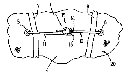
Fi ure 1 is a front view of part of an item of footwear having a
pair of fastening elements in accordance with the invention;
and
Fi ure 2 is a detailed view of the elements looking from the
right in Fig. 1.
DETAILED DESCRIPTION OF THE DRAWINGS
The drawing shows a fastening 1 as applied to a snowboard boot indicated
generally at 20, although a similar form of fastening may be used with other
kinds of footwear. The boot has an opening 4 with rows of eyelets 5 and 6
(only one eyelet on each side being shown) extending along opposite sides
7 and 8 of the opening. The eyelets are normally intended to receive a boot
lace, but each pair of eyelets receives a pair of fastening elements 10 and
11 formed of stiff but slightly springy stainless steel wire or similar
material.
The elements are pivotally engaged with the eyelets, e.g. by inserting
hooked ends through the eyelets. The elements could also carry back stops
which locate behind the rear of the eyelets, in which case the elements are
inserted by threading them through the eyelets from the rear. In boots of the
kind in which some or all of the eyelets are replaced by hooked plates the
elements may be provided with looped ends to pivotally engage the hooks.
The free end of the first fastening element 10 is formed with a screw thread
14 to receive a stainless steel bead 15, whereas the free end of the second
element 11 is bent orthogonally and formed into a clasp in the form of a U-

CA 02336555 2001-O1-03
WO 00/72716 PCT/GB00/01970
4
shaped, forwardly-directed hook 16, best seen in Fig. 2.
When the wearer has placed hislher foot into the boot the element 10 is
placed over the mouth of the hook 16. By applying gentle finger pressure
to the bead 15 the bead is caused to ride over the shank of the element 11,
as indicated by the large arrow in Fig. 2, so that the shank of the first
element 10 enters the mouth of the hook 16 so that the hook 16 embraces
the first element 10 and engages behind the bead 15. The tension in the
fastening can be adjusted by changing its length, which is easily achieved
by screwing the bead 15 along the thread 14.
It should be appreciated that when the boot is being worn the fastening is
primarily subjected to tensile stress so that the fastening is able to
withstand
considerable tension without coming apart due to the engagement of the
hook 16 behind the bead 15. On the other hand, application of moderate
forwardly-directed finger pressure to the first element 10 andlor the bead 16
will cause the bead to ride over the second element 11 and thereby
disengage the fastening.
Thus, the fastening is easy to engage and disengage when the wearer's
fingers are cold or when wearing heavy gloves, yet the fastening is secure
enough to be used with snowboarding or ski boots.
It will be appreciated that the features disclosed herein may be present in
any feasible combination. Whilst the above description lays emphasis on
those areas which, in combination, are believed to be new, protection is
claimed for any inventive combination of the features disclosed herein.

Representative Drawing
A single figure which represents the drawing illustrating the invention.
Administrative Status

2024-08-01:As part of the Next Generation Patents (NGP) transition, the Canadian Patents Database (CPD) now contains a more detailed Event History, which replicates the Event Log of our new back-office solution.

Please note that "Inactive:" events refers to events no longer in use in our new back-office solution.

For a clearer understanding of the status of the application/patent presented on this page, the site Disclaimer , as well as the definitions for Patent , Event History , Maintenance Fee  and Payment History  should be consulted.

Event History

Description Date
Application Not Reinstated by Deadline 2004-05-25
Time Limit for Reversal Expired 2004-05-25
Deemed Abandoned - Failure to Respond to Maintenance Fee Notice 2003-05-23
Inactive: Cover page published 2001-04-04
Inactive: First IPC assigned 2001-04-01
Inactive: Notice - National entry - No RFE 2001-03-20
Inactive: Inventor deleted 2001-03-20
Application Received - PCT 2001-03-19
Application Published (Open to Public Inspection) 2000-12-07

Abandonment History

Abandonment Date Reason Reinstatement Date
2003-05-23

Maintenance Fee

The last payment was received on 2002-05-21

Note : If the full payment has not been received on or before the date indicated, a further fee may be required which may be one of the following

  • the reinstatement fee;
  • the late payment fee; or
  • additional fee to reverse deemed expiry.

Patent fees are adjusted on the 1st of January every year. The amounts above are the current amounts if received by December 31 of the current year.
Please refer to the CIPO Patent Fees web page to see all current fee amounts.

Fee History

Fee Type Anniversary Year Due Date Paid Date
Basic national fee - small 2001-01-03
MF (application, 2nd anniv.) - small 02 2002-05-23 2002-05-21
Owners on Record

Note: Records showing the ownership history in alphabetical order.

Current Owners on Record
STEVEN JOHN CULVERWELL
Past Owners on Record
None
Past Owners that do not appear in the "Owners on Record" listing will appear in other documentation within the application.
Documents

To view selected files, please enter reCAPTCHA code :


To view images, click a link in the Document Description column (Temporarily unavailable). To download the documents, select one or more checkboxes in the first column and then click the "Download Selected in PDF format (Zip Archive)" or the "Download Selected as Single PDF" button.

List of published and non-published patent-specific documents on the CPD .

If you have any difficulty accessing content, you can call the Client Service Centre at 1-866-997-1936 or send them an e-mail at CIPO Client Service Centre.

({010=All Documents, 020=As Filed, 030=As Open to Public Inspection, 040=At Issuance, 050=Examination, 060=Incoming Correspondence, 070=Miscellaneous, 080=Outgoing Correspondence, 090=Payment})


Document
Description 
Date
(yyyy-mm-dd) 
Number of pages   Size of Image (KB) 
Representative drawing 2001-04-03 1 7
Description 2001-01-02 4 132
Abstract 2001-01-02 1 62
Claims 2001-01-02 2 37
Drawings 2001-01-02 1 14
Notice of National Entry 2001-03-19 1 194
Reminder of maintenance fee due 2002-01-23 1 111
Courtesy - Abandonment Letter (Maintenance Fee) 2003-06-22 1 174
PCT 2001-01-02 3 101
Fees 2002-05-20 1 31