Language selection

Search

Patent 2336912 Summary

Third-party information liability

Some of the information on this Web page has been provided by external sources. The Government of Canada is not responsible for the accuracy, reliability or currency of the information supplied by external sources. Users wishing to rely upon this information should consult directly with the source of the information. Content provided by external sources is not subject to official languages, privacy and accessibility requirements.

Claims and Abstract availability

Any discrepancies in the text and image of the Claims and Abstract are due to differing posting times. Text of the Claims and Abstract are posted:

  • At the time the application is open to public inspection;
  • At the time of issue of the patent (grant).
(12) Patent: (11) CA 2336912
(54) English Title: DEVICE FOR EMBOSSING GROOVED LINES IN CORRUGATED CARDBOARD
(54) French Title: DISPOSITIF POUR LE GAUFRAGE DE LIGNES RAINUREES DANS DU CARTON ONDULE
Status: Expired and beyond the Period of Reversal
Bibliographic Data
(51) International Patent Classification (IPC):
  • B31F 01/10 (2006.01)
  • B31B 50/25 (2017.01)
(72) Inventors :
  • GEHLE, HARALD (Germany)
(73) Owners :
  • HARALD GEHLE
(71) Applicants :
  • HARALD GEHLE (Germany)
(74) Agent: SMART & BIGGAR LP
(74) Associate agent:
(45) Issued: 2003-07-29
(86) PCT Filing Date: 1999-10-13
(87) Open to Public Inspection: 2000-04-20
Examination requested: 2001-01-08
Availability of licence: N/A
Dedicated to the Public: N/A
(25) Language of filing: English

Patent Cooperation Treaty (PCT): Yes
(86) PCT Filing Number: PCT/EP1999/007712
(87) International Publication Number: EP1999007712
(85) National Entry: 2001-01-08

(30) Application Priority Data:
Application No. Country/Territory Date
198 49 282.0 (Germany) 1998-10-15

Abstracts

English Abstract


The invention relates to a
device for stamping groove lines
on corrugated board to better
fold and comply with the sizes of
boxes in production and processing
machines having a combined
grooving and transport body (1)
and a counter-body. The combined
grooving and transport body (1)
is fitted on its periphery with a
grooving ring (11) having straight
individual surfaces, said ring having
the shape of a regular polygon
with straight fiat pieces whose
number varies due to the different
peripheries.


French Abstract

L'invention concerne un dispositif pour imprimer des lignes formant des rainures dans du carton ondulé, cela pour permettre d'obtenir un meilleur pliage et le respect des dimensions lors de formation de boîtes, pour des machines de production et de traitement, lequel comporte un corps de rainurage et de transport (1) combiné et un contre-corps. Le corps de rainurage et de transport (1) combiné est pourvu, sur sa périphérie, d'une bague de rainurage (11) droite au niveau de ses surfaces individuelles, qui présente la forme d'un polygone régulier comportant un nombre de parties planes droites variant en raison de la différence de périphérie.

Claims

Note: Claims are shown in the official language in which they were submitted.

Patent Claims
1. A device for embossing grooved lines in corrugated cardboard (3) to
facilitate folding
and to maintain the required box dimensions for production and processing
machines
having a combined grooving and conveyor body (1) and a mating body (2),
characterized
in that the combined grooving and conveyor body (1) is provided on its
circumference (4)
with a number of flat pieces (10, 10', 10") which varies according to the
outside diameter,
running in the plane of rotation of the combined grooving and conveyor body
(1) and
forming a polygonal grooving ring (11) which projects radially beyond the
circumference
(4) of the combined grooving and conveyor body (1).
2. A device according to Claim 1, characterized in that the conveyor body (1)
is mounted on
the machine frame in such a way that it is adjustable in height with respect
to the mating
body (2).
3. A device according to Claim 1, characterized in that the polygonal grooving
ring (11) is 1
to 5 mm thick.
4. A device according to Claim 1, characterized in that each flat piece (10,
10', 10") of the
polygonal grooving ring (11) is 5 to 20 mm long.
6

Description

Note: Descriptions are shown in the official language in which they were submitted.


CA 02336912 2001-O1-08
WO 00/21741 PCT/EP99/07712
Translation from German
Device for Embossing Grooved Lines in Corrugated Cardboard
The present invention relates to a device for embossing groovedi lines in
corrugated cardboard in
processing machines according to the definition of the species of Patent Claim
1
In the corrugated cardboard industry, grooving or scoring is produced
automatically in the
longitudinal direction of the machine by means of grooving blades or rings.
This grooving,
which determines where the cardboard blank is to be folded subsequently, is
especially critical
and produces uncontrolled gap widths in the finished folded box according to
the state of the art
today. This is solely the result of the unsatisfactory grooving.
Grooving is performed in the longitudinal direction of the corrugated
cardboard and thus
longitudinally to the corrugations in the cardboard, therefore always
encountering different
conditions from the peaks to the valleys of the corrugations. Since the
cardboard is folded over
belts, a phenomenon called fish=tailing occurs when the folding runs slightly
toward the rear in
the case when the embossing of the corrugations is less than 100%.
The embossing of corrugations is also influenced by the grade of paper used.
Lightweight paper
and recycled grades of paper cannot be embossed to the full extent because
these types of paper
easily develop cracks and thus reduce the loading capacity of the folded
boxes.
German Patent 31 38 454 C2 discloses a device and a method for embossing
grooves in
corrugated cardboard for folding and maintaining the dimensions of the
cardboard for corrugated
cardboard grooving machines, where the corrugated cardboard or the cardboard
which is to be
l~The German word "Ripen" can refer to both "corrugations" and "scoring" (to
produce the fold lines). In the absence of the patent diagrams, 1 have called
this "grooving" to
cover both cases - Translator's note]

CA 02336912 2001-O1-08
WO 00/21741 PCT/EP99/07712
provided with grooves is passed between two rolls and is thereby scored. The
distance between
the two rolls is adjusted in advance according to the thickness of the
cardboard to be scored, so
that the correct pressure is applied to the material to be scored.
German Patent 36 17 916 A1 discloses a method and a device for producing
blanks for folded
boxes, where the blank is conveyed through a feed station, an embossing
station, a cooling
station, a punching station and a discharge station in succession with the
help of a conveyor
device. Such a machine is known as an in-line machine, because several
operations are carned
out in one machine. In the case of the known device, the embossing station has
a hydraulically or
mechanically driven embossing press with a stationary base plate and a
vertically movable upper
pressure plate. Both plates have heating plates whose temperature can be
adjusted independently
of the other. Since the heating plates are mounted on the embossing die, the
embossing or
corrugating is always accompanied by heating and thus is a stationary process.
The machine
must operate intermittently, i.e., the conveyor device must first pass a blank
sheet beneath the
embossing die, then stop to close the embossing die and remain closed until
the heating plates
have been adequately heated. Then the embossing force is increased to emboss
the embossing
lines. Then the embossing die opens and the conveyor device starts up again,
conveying the
blank sheet thus corrugated to the cooling station. One disadvantage of this
known device and
the method that can be carried out with it is that the conveyor device must be
repeatedly braked
and then must start up again, which necessitates repeated braking and
deceleration of substantial
weights and causes a high power consumption. This is of course also subject to
natural limits on
speed..
Finally, German Patent Application 195 38 512 A1 describes a method and a
device for
embossing scored lines in corrugated cardboard for better folding and to
maintain the correct box
dimensions for in-line machines. Immediately before grooving or during the
grooving itself, the
part of the corrugated cardboard provided for grooving is heated with the help
of a heatable
table.

CA 02336912 2001-O1-08
WO 00/21741 PCT/EP99/07712
In the case of all the known methods, the grooving is performed as a
rotational process and is
usually performed in the longitudinal direction of the corrugations in the
cardboard, so the
grooving point begins at different points in the corrugations. This causes
great problems in the
so-called gap tolerance, which is very important in automatic packaging
because it determines
the accuracy in folding the box.
The object of the present invention is to provide a device with which more
accurate grooving of
corrugated cardboard can be achieved than in the related art for the
subsequent production of
folded boxes.
A device having the features of Patent Claim 1 is used to achieve this object.
Advantageous embodiments of the present invention are derived from the
subordinate claims.
Although the corrugated cardboard is conveyed with a rotating ring in the
present invention, the
actual grooving is embossed by a varying number of straight lines, depending
on the outside
diameter of the ring.
The present invention is explained in greater detail below on the basis of a
drawing:
Figure 1 shows an embodiment schematically;
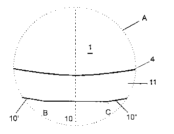
Figure 2 shows a detail A of the grooving body from Figure 1.
The same parts are provided with the same reference numbers in these figures.
Figure 1 shows a diagram of a top and bottom conveyor body 1 and 2 in a
printing, folding and
gluing machine for corrugated cardboard 3, which is also referred to in
general as an in-line
machine. These conveyor bodies 1, 2 are necessary for cycled advance within
the machine.

CA 02336912 2001-O1-08
WO 00/21741 PCT/EP99/07712
The conveyor bodies 1 and 2 are mounted in a known way on driven shafts in an
in-line
machine. One of these conveyor bodies 1 or 2, depending on the machine design
for top pressure
or bottom pressure, is provided on the circumference 4 with a varying number
of straight flat
pieces 10, 10' and 10" which are distributed uniformly over the circumference
4, imparting a
polygonal or mufti-sided appearance to conveyor body 1 as seen in plan view.
These straight flat
pieces 10, 10', 10" are between 5 mm and 25 mm long, depending on the outside
diameter of the
conveyor body 1.
The combined grooving and conveyor body 1 which has been provided with these
flat pieces 10,
10', 10" is usually made of steel or cast iron and presses the part of
corrugated cardboard 3 which
is to be grooved against the outer circumference of the lower conveyor body 2,
which is referred
to as a counter mold and has either a steel or polyurethane working surface.
The straight flat pieces 10, 10', 10" provided over the outside diameter of
the upper (or lower)
conveyor body 1 produce the desired grooving in corrugated cardboard, namely
similar to that
which would be achieved with a stationary strut. The difference in comparison
with the normal
corrugations known today, produced by a round grooving body, consists of the
fact that the
invention described here executes a horizontal embossing and thus permits
satisfactory folding of
finished sheets of corrugated cardboard.
The combined grooving and conveyor body 1 thus has a polygonal grooving ring
11 which
projects approx. 1 to 4 mm above the circumference 4 of its circular conveyor
body 1 and has a
width of 0.5 mm to 4 mm, with the edges being rounded. The outside contour
over the largest
circumference 4 of the combined grooving and conveyor body 1 is thus that of a
regular polygon
with 70 corners, for example, which is not indicated in Figure 1, because it
shows the grooving
ring only schematically.
Figure 2 shows an enlargement of detail A from Figure 1, showing a better view
of the straight

CA 02336912 2001-O1-08
WO 00/21741 PCT/EP99/07712
flat pieces 10, 10', 10". The circumference 4 of the conveyor body 1 thus
extends as the arc of a
circle, while the outside contour of flat pieces 10, 10', 10" is straight
between points B and C and
also to the right and left of them.

Representative Drawing
A single figure which represents the drawing illustrating the invention.
Administrative Status

2024-08-01:As part of the Next Generation Patents (NGP) transition, the Canadian Patents Database (CPD) now contains a more detailed Event History, which replicates the Event Log of our new back-office solution.

Please note that "Inactive:" events refers to events no longer in use in our new back-office solution.

For a clearer understanding of the status of the application/patent presented on this page, the site Disclaimer , as well as the definitions for Patent , Event History , Maintenance Fee  and Payment History  should be consulted.

Event History

Description Date
Time Limit for Reversal Expired 2018-10-15
Change of Address or Method of Correspondence Request Received 2018-03-28
Letter Sent 2017-10-13
Inactive: IPC deactivated 2017-09-16
Inactive: IPC from PCS 2017-01-07
Inactive: IPC expired 2017-01-01
Maintenance Request Received 2016-10-12
Maintenance Request Received 2015-09-28
Maintenance Request Received 2014-10-08
Maintenance Request Received 2013-10-11
Maintenance Request Received 2012-10-15
Grant by Issuance 2003-07-29
Inactive: Cover page published 2003-07-28
Pre-grant 2003-05-08
Inactive: Final fee received 2003-05-08
Letter Sent 2002-12-03
Notice of Allowance is Issued 2002-12-03
Inactive: Approved for allowance (AFA) 2002-11-19
Inactive: Entity size changed 2002-08-07
Inactive: Cover page published 2001-04-26
Inactive: First IPC assigned 2001-04-11
Inactive: Acknowledgment of national entry - RFE 2001-03-28
Inactive: Inventor deleted 2001-03-27
Application Received - PCT 2001-03-20
All Requirements for Examination Determined Compliant 2001-01-08
Request for Examination Requirements Determined Compliant 2001-01-08
Application Published (Open to Public Inspection) 2000-04-20

Abandonment History

There is no abandonment history.

Maintenance Fee

The last payment was received on 2002-07-23

Note : If the full payment has not been received on or before the date indicated, a further fee may be required which may be one of the following

  • the reinstatement fee;
  • the late payment fee; or
  • additional fee to reverse deemed expiry.

Patent fees are adjusted on the 1st of January every year. The amounts above are the current amounts if received by December 31 of the current year.
Please refer to the CIPO Patent Fees web page to see all current fee amounts.

Owners on Record

Note: Records showing the ownership history in alphabetical order.

Current Owners on Record
HARALD GEHLE
Past Owners on Record
None
Past Owners that do not appear in the "Owners on Record" listing will appear in other documentation within the application.
Documents

To view selected files, please enter reCAPTCHA code :


To view images, click a link in the Document Description column. To download the documents, select one or more checkboxes in the first column and then click the "Download Selected in PDF format (Zip Archive)" or the "Download Selected as Single PDF" button.

List of published and non-published patent-specific documents on the CPD .

If you have any difficulty accessing content, you can call the Client Service Centre at 1-866-997-1936 or send them an e-mail at CIPO Client Service Centre.


Document
Description 
Date
(yyyy-mm-dd) 
Number of pages   Size of Image (KB) 
Abstract 2001-01-07 1 13
Description 2001-01-07 5 191
Claims 2001-01-07 1 29
Drawings 2001-01-07 1 11
Representative drawing 2001-04-25 1 3
Notice of National Entry 2001-03-27 1 202
Reminder of maintenance fee due 2001-06-13 1 112
Commissioner's Notice - Application Found Allowable 2002-12-02 1 160
Maintenance Fee Notice 2017-11-23 1 177
Correspondence 2003-05-07 1 32
PCT 2001-04-08 3 96
PCT 2001-01-07 10 302
Fees 2006-10-04 1 34
Fees 2009-10-08 1 40
Fees 2010-10-06 1 34
Fees 2011-10-10 1 66
Fees 2012-10-14 1 67
Fees 2013-10-10 2 75
Fees 2014-10-07 2 83
Maintenance fee payment 2015-09-27 2 86
Maintenance fee payment 2016-10-11 2 84