Language selection

Search

Patent 2337253 Summary

Third-party information liability

Some of the information on this Web page has been provided by external sources. The Government of Canada is not responsible for the accuracy, reliability or currency of the information supplied by external sources. Users wishing to rely upon this information should consult directly with the source of the information. Content provided by external sources is not subject to official languages, privacy and accessibility requirements.

Claims and Abstract availability

Any discrepancies in the text and image of the Claims and Abstract are due to differing posting times. Text of the Claims and Abstract are posted:

  • At the time the application is open to public inspection;
  • At the time of issue of the patent (grant).
(12) Patent Application: (11) CA 2337253
(54) English Title: AN UNMANNED VEHICLE FOR DISPLACING MANURE
(54) French Title: VEHICULE TELEGUIDE DE DEPLACEMENT DE FUMIER
Status: Deemed Abandoned and Beyond the Period of Reinstatement - Pending Response to Notice of Disregarded Communication
Bibliographic Data
(51) International Patent Classification (IPC):
  • A01K 01/01 (2006.01)
(72) Inventors :
  • VAN DEN BERG, KAREL
(73) Owners :
  • LELY ENTERPRISES AG
(71) Applicants :
  • LELY ENTERPRISES AG (Switzerland)
(74) Agent: SMART & BIGGAR LP
(74) Associate agent:
(45) Issued:
(86) PCT Filing Date: 2000-05-10
(87) Open to Public Inspection: 2000-11-30
Availability of licence: N/A
Dedicated to the Public: N/A
(25) Language of filing: English

Patent Cooperation Treaty (PCT): Yes
(86) PCT Filing Number: PCT/NL2000/000314
(87) International Publication Number: NL2000000314
(85) National Entry: 2001-01-12

(30) Application Priority Data:
Application No. Country/Territory Date
1012143 (Netherlands (Kingdom of the)) 1999-05-25

Abstracts

English Abstract


The invention relates to an unmanned vehicle for displacing manure over a
stable floor, comprising a steering unit for steering the vehicle and a frame
(1) and first, second and third supporting means for supporting the frame on
the floor, the first and second supporting means being rollable relative to
the floor and the third supporting means comprising manure displacing means
for displacing manure, while the first supporting means comprise a propelling
unit (2) for propelling the vehicle, said propelling unit comprising two
independently driven propelling members and the steering unit being
constituted by the propelling unit.


French Abstract

L'invention concerne un véhicule téléguidé destiné au déplacement du fumier sur le plancher d'une étable et comprenant un organe de direction destiné à diriger le véhicule et un cadre (1), ainsi qu'un premier, un deuxième et un troisième dispositif de support destinés à servir de support au cadre sur le plancher, les premier et deuxième dispositifs de support étant capables de rouler sur le plancher et le troisième dispositif de support comportant un organe de déplacement de fumier destiné à déplacer le fumier. Le premier dispositif de support comprend une unité (2) de propulsion destinée à propulser le véhicule, cette unité de propulsion comportant deux éléments de propulsion indépendamment commandés, et l'organe de direction étant constitué de l'unité de propulsion.

Claims

Note: Claims are shown in the official language in which they were submitted.

5
CLAIMS
1. An unmanned vehicle for displacing manure over a
stable floor, comprising a steering unit for steering the
vehicle and a frame (1) with first, second and third
supporting means for supporting the frame (1) on the floor,
while the first and second supporting means are rollable
relative to the floor and the third supporting means comprise
manure displacing means for displacing manure, the first
supporting means comprising a propelling unit (2) for
propelling the vehicle, characterized in that the propelling
unit comprises two independently drivable propelling members
and the steering unit is constituted by the propelling unit.
2. An unmanned vehicle as claimed in claim 1,
characterized in that at least one of the supporting means is
provided with pressure setting means for setting the pressure
with which the manure displacing means press on the floor.
3. An unmanned vehicle for displacing manure over a
stable floor, comprising a steering unit for steering the
vehicle and a frame (1) with first, second and third
supporting means for supporting the frame (1) on the floor,
while the first and second supporting means are rollable
relative to the floor and the third supporting means comprise
manure displacing means for displacing manure, the first
supporting means comprising a propelling unit (2) for
propelling the vehicle, characterized in that at least one of
the supporting means is provided with pressure setting means
for setting the pressure with which the manure displacing
means press on the floor.
4. An unmanned vehicle as claimed in any one of the
preceding claims, characterized in that the second supporting
means comprise at least one freely rotatable propelling
member.
5. An unmanned vehicle as claimed in any one of the
preceding claims, characterized in that the propelling member
comprises a wheel (4) and/or a caterpillar track.

6
6. An unmanned vehicle as claimed in any one of the
preceding claims, characterized in that the second supporting
means are disposed between the first and the third supporting
means.
7. An unmanned vehicle as claimed in any one of the
preceding claims, characterized in that the unmanned vehicle
is equipped with orientation means for following a path in a
space or determining the position of the vehicle in a space,
such as a stable or a meadow.
8. An unmanned vehicle as claimed in any one of the
preceding claims, characterized in that the unmanned vehicle
is equipped with protective facilities for protecting the
vehicle against obstacles, such as a cow's leg.
9. An unmanned vehicle as claimed in claim 8,
characterized in that the protective means are provided
equipped with positioning means for determining the position
of an obstacle relative to the unmanned vehicle.
10. An unmanned vehicle as claimed in claim 9,
characterized in that the signal from the positioning means is
used for actuating the steering unit.
11. An unmanned vehicle as claimed in any one of the
preceding claims, characterized in that the manure displacing
means comprise at least one brush and/or at least one manure
slide (3) and/or at least one spraying unit.
12. An unmanned vehicle as claimed in any one of the
preceding claims, characterized in that the unmanned vehicle
is equipped with anti-bumping means for preventing the manure
displacing means from moving too far away from the floor.

Description

Note: Descriptions are shown in the official language in which they were submitted.


CA 02337253 2001-O1-12
WO 00/70938 PCT/NL00/00314
AN UNMANNED VEHICLE FOR DISPLACING MANURE
The invention relates to an unmanned vehicle
according to the preamble of claim 1.
In modern stables there is usually applied a stable
floor in which there are provided apertures for letting
through cow manure. Under the stable floor there is provided a
receptacle in which the manure passed through is collected.
Generally there is provided in the stable a so-called manure
slide which moves through the stable at fixed points of time
and displaces the manure partially to the dung pit and
partially through the apertures in the stable floor.
A new development is an unmanned vehicle for
displacing manure. Such an implement is known from e.g.
Messrs. Joz B.V. as the JOZTECH (Landbouw Rai (Agricultural
Rai), Amsterdam, January 1999). This implement is provided
with a first propelling unit comprising two freely rotatable
wheels and a second propelling unit comprising one driven and
controllable wheel. The disadvantage of said implement is that
the construction of the driven and controllable wheel is
complicated and therefore expensive. Moreover, the
construction is very sensitive to dirt, which is not desirable
in the stable environment. Finally, the JOZTECH is driven by
only one controllable wheel, so that wheel skidding often
occurs on the stable floor which is very slippery due to the
presence of manure. As a result thereof it is not possible to
determine the exact position of the vehicle on the basis of
the number of revolutions of the driven wheel.
The invention aims at obviating the above-mentioned
drawbacks by means of an unmanned vehicle according to the
characterizing part of claim 1. The advantage of this unmanned
vehicle is that the drive unit of the propelling members also
constitutes the steering unit of the unmanned vehicle.
Accordingly, there is achieved a compact construction which is
insensitive to dirt and which, besides, is less complicated,
so that lower manufacture costs are involved.

CA 02337253 2001-O1-12
WO 00/70938 2 PCT/NL00/00314
According to a further inventive feature, at least
one of the supporting means is provided with pressure setting
means for setting the pressure with which the manure
displacing means press on the floor. Therefore, the invention
relates to an unmanned vehicle for displacing manure over a
stable floor, comprising a steering unit for steering the
vehicle and a frame with first, second and third supporting
means for supporting the frame on the floor, while the first
and second supporting means are rollable relative to the floor
l0 and the third supporting means comprise manure displacing
means for displacing manure, the first supporting means
comprising a propelling unit for propelling the vehicle,
characterized in that at least one of the supporting means is
provided with pressure setting means for setting the pressure
with which the manure displacing means press on the floor. The
second propelling unit comprises at least one freely rotatable
propelling member. The propelling members are preferably
designed as a wheel and/or a caterpillar track. In a preferred
embodiment the rotatable propelling member consists of a
castor wheel as a result of which the unmanned vehicle has an
excellent manoeuvrability. Caterpillar tracks have the
advantage of being less sensitive to skidding than wheels.
In accordance with another inventive feature, the
unmanned vehicle is equipped with orientation means for
following a path in a space, or determining the position of
the vehicle in a space, such as a stable or a meadow. The
orientation means comprise floor detection means for detecting
apertures in the floor and/or detecting a guide means in the
floor, such as the reinforcement in the concrete or an
3o electricity conducting wire. The apertures in the floor are
usually provided for removing the manure as described above.
When the stable floor is made of concrete, there is usually
applied a metal grid in the floor for giving it extra
strength. Said grid can be detected by means of the floor
detection means with the aid of e.g. an induction coil.
Additional orientation means may comprise a compass and/or a
gyroscope and/or a spirit level and/or a clinometer and/or an

CA 02337253 2001-O1-12
WO 00/70938 3 PCT/NL00/00314
acceleration meter. These orientation means are nowadays
available in a form which is suitable for being applied in
electronic circuits, so that integrated orientation means can
easily be composed from the various components.
Besides, the orientation means also comprise wall
following means for detecting and following a wall, such as a
fixed stable wall or the edge of a cubicle. These wall
following means extend over at least part of the circumference
of the unmanned vehicle. The wall following means may also be
to disposed on the manure displacing means. In a preferred
embodiment, the wall following means consist of a freely
rotating substantially round element, such as preferably a
wheel and/or a disc and/or a sphere.
According to another inventive feature, the unmanned
15 vehicle is equipped with protective facilities for protecting
the vehicle against obstacles, such as cows' legs, or fixed
objects, such as supporting pillars in the stable. The
protective facilities may comprise a bumper and/or a sensor
for detecting cows. The protective facilities may also
20 comprise wall following means. The protective facilities may
also comprise positioning means for determining the position
of an obstacle relative to the unmanned vehicle. The
positioning means may also comprise a clinometer and/or an
acceleration meter. The positioning means are preferably
25 disposed on the wall following means. In this manner it is
possible to determine the angular deflection and angular
acceleration of e.g. the wall following means, so that
information is obtained regarding the position of the
obstacle. The signal from the positioning means is used for
30 actuating the steering unit.
The manure displacing means preferably comprise at
least one brush and/or at least one manure slide and/or at
. least one spraying unit.
In accordance with a last inventive feature, the
35 unmanned vehicle is equipped with anti-bumping means for
preventing the manure displacing means from moving too far
away from the floor. The anti-bumping means comprise a bumper

CA 02337253 2001-O1-12
WO 00/70938 4 PCT/NL00/00314
and/or a bracket. The anti-bumping means preferably comprise
an anti-bumping sensor for detecting the movement of the
manure displacing means away from the floor, which anti-
bumping sensor is coupled to the propelling unit. Such an
anti-bumping sensor may consist of a switch which is disposed
on the bumper or bracket. When the manure slide moves too far
away from the stable floor, the switch touches the stable
floor, whereupon the unmanned vehicle is caused to run in an
opposite direction and bears again with all its supporting
means on the stable floor.
The invention will now be explained in further detail
with reference to i~he accompanying drawing, in which
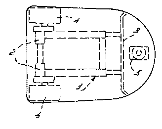
Figure 1 is a plan view of the unmanned vehicle.
The unmanned vehicle as shown in Figure 1 consists of
a frame 1 to which there are fitted a castor wheel 5, the
propelling unit 2 and the manure slide 3. The steering unit is
constituted by the propelling unit 2, which propelling unit 2
comprises two independently driven wheels 4. In this
embodiment manoeuvring the vehicle is possible by varying the
drive torque or the peripheral velocity of the wheels 4. The
wheels 4 may comprise a wheel and/or a caterpillar track.

Representative Drawing
A single figure which represents the drawing illustrating the invention.
Administrative Status

2024-08-01:As part of the Next Generation Patents (NGP) transition, the Canadian Patents Database (CPD) now contains a more detailed Event History, which replicates the Event Log of our new back-office solution.

Please note that "Inactive:" events refers to events no longer in use in our new back-office solution.

For a clearer understanding of the status of the application/patent presented on this page, the site Disclaimer , as well as the definitions for Patent , Event History , Maintenance Fee  and Payment History  should be consulted.

Event History

Description Date
Application Not Reinstated by Deadline 2005-05-10
Time Limit for Reversal Expired 2005-05-10
Deemed Abandoned - Failure to Respond to Maintenance Fee Notice 2004-05-10
Letter Sent 2002-08-28
Inactive: Entity size changed 2002-05-02
Inactive: Cover page published 2001-04-26
Inactive: First IPC assigned 2001-04-11
Letter Sent 2001-03-27
Inactive: Notice - National entry - No RFE 2001-03-27
Application Received - PCT 2001-03-20
Application Published (Open to Public Inspection) 2000-11-30

Abandonment History

Abandonment Date Reason Reinstatement Date
2004-05-10

Maintenance Fee

The last payment was received on 2003-04-23

Note : If the full payment has not been received on or before the date indicated, a further fee may be required which may be one of the following

  • the reinstatement fee;
  • the late payment fee; or
  • additional fee to reverse deemed expiry.

Patent fees are adjusted on the 1st of January every year. The amounts above are the current amounts if received by December 31 of the current year.
Please refer to the CIPO Patent Fees web page to see all current fee amounts.

Fee History

Fee Type Anniversary Year Due Date Paid Date
Registration of a document 2001-01-12
Basic national fee - small 2001-01-12
Registration of a document 2002-01-14
MF (application, 2nd anniv.) - standard 02 2002-05-10 2002-04-22
Registration of a document 2002-08-30
MF (application, 3rd anniv.) - standard 03 2003-05-12 2003-04-23
Owners on Record

Note: Records showing the ownership history in alphabetical order.

Current Owners on Record
LELY ENTERPRISES AG
Past Owners on Record
KAREL VAN DEN BERG
Past Owners that do not appear in the "Owners on Record" listing will appear in other documentation within the application.
Documents

To view selected files, please enter reCAPTCHA code :


To view images, click a link in the Document Description column. To download the documents, select one or more checkboxes in the first column and then click the "Download Selected in PDF format (Zip Archive)" or the "Download Selected as Single PDF" button.

List of published and non-published patent-specific documents on the CPD .

If you have any difficulty accessing content, you can call the Client Service Centre at 1-866-997-1936 or send them an e-mail at CIPO Client Service Centre.


Document
Description 
Date
(yyyy-mm-dd) 
Number of pages   Size of Image (KB) 
Representative drawing 2001-04-25 1 6
Description 2001-01-11 4 209
Claims 2001-01-11 2 99
Drawings 2001-01-11 1 7
Abstract 2001-01-11 1 52
Notice of National Entry 2001-03-26 1 193
Courtesy - Certificate of registration (related document(s)) 2001-03-26 1 113
Reminder of maintenance fee due 2002-01-13 1 111
Courtesy - Abandonment Letter (Maintenance Fee) 2004-07-04 1 175
Reminder - Request for Examination 2005-01-10 1 115
PCT 2001-01-11 4 146
Correspondence 2002-03-21 1 21