Note: Descriptions are shown in the official language in which they were submitted.
CA 02337356 2001-02-15
GOLF BAG PULL CART HAVING INTEGRAL
EXTENC)ABLE ROLLERS AND HANDLE
BACKt~ROUND OF THE INVENTION
The present invention relates to golf bags and carts. More
specifically, the present invention relates to a golf bag pull cart having
laterally
extending wheels and an integral extendable arm which provides a handle for
the pull cart.
A golf bag is considered standard equipment for any golfer. A golf
bag typically includes an elongated, open-top container which accommodates
the length of golf clubs, and also various pockets for golf balls, tees,
towels,
shoes and other golf related items. A golfer can either carry the golf bag
over
his or her shoulders using straps, tote the golf bag on a riding cart, or
place the
golf bag on a separate device known as a pull cart.
Many golfers prefer walking to avoid the costs of a riding cart or to
obtain a degree of exercises while golfing. Although a golf bag is convenient
for
its ease of carrying from one location to another, it becomes quite heavy and
cumbersome when carried over the length of a golf course. The golf bag can
also cause soreness to thE: golfer's back and shoulder area. As a result, pull
carts are frequently used on the golf course in order to obtain the benefits
of
walking without the need to carry the bag. However, the use of pull carts has
its disadvantages.
The golf pull cart is generally constructed of a rigid metal frame
with golf bag securing straps, outspread wheels and an upwardly extended
handle. Although the cart performs adequately on the golf course, it is often
heavy and bulky. Loading the cart and bag when strapped together in a trunk
can be very difficult, and both may not fit in the trunks of smaller cars.
Oftentimes, the golf bag must be separated from the cart and the cart
transported and stored separately. This requires the re-strapping of the bag
to the cart when reaching the golf course. Due to the awkwardness of handling
typical golf bag pull carts, golfers often leave their own pull carts at homE;
and
rent a cart at the golf course when traveling.
CA 02337356 2001-02-15
-2-
Attempts have been made to devise foldable golf carts which aid
in transportation; however, these foldable pull carts are also heavy and
oftentimes bulky as well. ,4nother problem associated with prior foldable pull
carts is that they require the loosening and re-tightening of parts in order
to
unfold the cart for use. Oirher attempts have been made to combine the pull
cart and golf bag into one unit. However, these devices are usually heavy and
bulky as they are comprised of the essential components of a pull cart
attached to a golf bag. IVlany of these devices are also complex in their
construction and difficult to manipulate and operate.
Therefore, what is needed is a golf bag which can be easily pulled
behind a golfer on a golf course and yet is relatively light weight, simple in
construction and easy to operate, store and transport. The present invention
fulfills these needs, and provides other related advantages.
SUMMARY OF THE INVENTION
The present invention resides in a golf bag pull cart comprising,
generally, a support frame having a base and a spine extending upwardly from
the base, and an elongated arm which is pivotally attached to the spine so as
to position a handle adjacent to the spine in a folded carrying position, and
away from the spine in an extended position. A pair of wheels are affixed to
the frame adjacent to the base and rotated about a common axis. The wheels
are extendable away from and retractable towards the base along the axis.
A locking clasp is associated with the arm and connected to the
spine so as to permit the arm to pivot. The locking clasp includes first and
second discs which each have uniform radial interfitting teeth that allow the
discs to be rotated relativE: to one another and locked in place. A tightening
screw is inserted through aligned apertures of the first and second discs for
securely fastening the locking clasp together.
In one illustrated form of the invention, the spine and base of the
support frame are integrally formed into a golf bag. The base is formed at a
bottom of the golf bag and the spine extends upwardly from the base along a
CA 02337356 2001-02-15
-3-
side thereof. The golf bag itself includes recesses formed at the base for
receiving the wheels when retracted. One or more shoulder straps are
connected from an upper 1:o a lower end of the golf bag. A support stand may
also be connected to the golf bag.
In another illustrated form of the invention, the golf bag is exteriorly
supported by the base and the spine and fastened thereto by retaining straps.
Other features and advantages of the present invention will
become apparent from the following more detailed description, taken in
conjunction with the accompanying drawings which illustrate, by way of
example, the principles of the invention.
BRIEF DESCRIPTION OF THE DRAWINGS
The accompanying drawings illustrate the invention. In such
drawings:
FIGURE 1 is .a rear and side perspective view of a golf bag pull
cart embodying the present invention;
FIGURE 2 is a partially fragmented rear elevational view of the golf
bag pull cart of FIG.1, illustrating the extension of an elongated arm from a
support frame integrated into the golf bag and extension of the wheels from a
base;
FIGURE 3 is a partially fragmented rearelevational view ofthe golf
bag pull cart of FIGS. 1 and 2, illustrating the retraction of the elongated
arm
into the golf bag and retraction of the wheels into recesses formed in the
base;
FIGURE 4 is a front elevational view of a second embodiment of
the golf bag pull cart of the present invention, illustrating the elongated
arm
partially extended from a spine of the support frame;
FIGURE 5 is a side and front perspective view of the golf bag pull
cart of FIG. 4, illustrating, in phantom, a golf bag securely fastened to the
support frame;
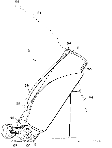
FIGURE 6 is perspective view of a third embodiment of the present
invention, illustrating a handle which extends from a locking clasp and is
CA 02337356 2001-02-15
-4-
pivotable between a folded position and an extended position (shown in
phantom); and
FIGURE 7 is a~n exploded perspective view of the locking clasp of
FIG. 6.
DETAILED DESCRIPTION OF THE PREFERRED EMBODIMENTS
As shown in the drawings for purposes of illustration, the present
invention is concerned with a golf bag pull cart, generally referred to by the
reference number 10 in FIGS. 1-3; by the reference number 12 in FIGS. 4 and
5, and by the reference number 13 in FIG. 6. In the following description,
functionally equivalent elernents of the illustrated embodiments will be
referred
to by the same reference number.
In accordance with the present invention, the golf bag pull carts 10,
12 and 13 each include a support frame 14 comprised of a base 16 and a
spine 18 extending vertically from the base 16. The base 16 and spine 18~ may
be integrally formed with one another, or attached securely to one another.
The support frame 14 may be comprised of any rigid and durable material
capable of supporting the weight of a golf bag 20 filled with golf clubs and
other
golf equipment while rigorously being pulled across a golf course. Yet, the
frame 14 of the golf bag pull cart 12 should weigh as little as possible so as
not
to tire the golfer. Light steel, metal alloys, such as an aluminum alloy, and
hardened plastic are preferred.
A pair of wheels 22 are rotatably affixed adjacent the base 16.
Typically, the wheels 22 aide disposed on opposing ends of an axle 24 which
is formed with or otherwisf~ attached to the base 16 of the support frame 14.
As illustrated in FIG. 4, the wheels 22 are extendable along the longitudinal
axis of the axle 24 away from the base 16. Likewise, the wheels 22 are
retractable towards the base 16. Preferably, the wheels 22 lock into a fully
extended position and remain in the locked position until the golfer retracia
the
wheels 22 towards the base 16, where the wheels 22 may lock into a fully
retracted position. The locked wheels 22 prevent the golf bag pull cart 10,12
CA 02337356 2001-02-15
-5-
and 13 from becoming unstable due to the unexpected retraction of the wheels
22 while being pulled across the golf course or unexpected extension while in
storage. More than one locking position can be provided for differing terrain
or the individual golfer's specific needs.
Referring to FIGS. 1-5, the spine 18 is at least partially hollow so
as to slidably accept an elongated arm 26 having a handle 28 and a shaft 30
extending downwardly therefrom. The shaft 30 is preferably comprised of two
parallel posts 32 which slide into the spine 18. In this preferred form, the
handle 28 is U-shaped to conform to the spine 18, while also providing an
effective handgrip. The arm 26 is extended when the golfer grasps the handle
28 and pulls the handle 2.g away from the spine 18. The arm 22 is retracted
into the spine 18 by pushing the handle 28 downwardly until it is fully
retracted
adjacent the spine 18.
A locking mechanism 34 provides a means for locking the arm 26
in its fully retracted or extended positions. The locking mechanism 34
includes
spring biased fingers 36 associated with the shaft 30 and finger receiving
recesses 38 associated with the spine 18. The fingers 36 engage the
recesses 38 when the arm 26 is in the fully extended or fully retracted
positions. The fingers 36 are released from the recesses 38 by pressing a
release button 40.
Referring more specifically to FIGS. 1-3, a first embodiment of the
golf bag pull cart 10 incorporates the base 16 and spine 18 of the frame 14
into
the golf bag 20. The base 16 is formed at a bottom portion of the golf bag 20
and the spine 18 extends up a side of the golf bag 20 to a top edge of the
golf
bag 20, giving the golf bad 20 a defined shape and support. The golf b<~g 20
is comprised of any lightweight durable material such as a plastic shell,
nylon
fabric, polypropylene or any other suitable material. The golf bag 20 is
formed
like typical golf bags having a generally cylindrical and hollow body so as to
accept golf clubs into an open top. The golf bag 20 may include dividers
within
the hollow body to separate and protect the shafts of the golf clubs and
pockets on the exterior of the golf bag 20 to carry other golf equipment such
as shoes, tees and golf balls as is necessary.
CA 02337356 2001-02-15
-6-
As illustrated in FIG. 1, the golf bag pull cart 10 may have a grip
42 attached on the golf bag 20 to facilitate moving the golf bag 20 a short
distance using only one hand. The golf bag 20 may also incorporate a golf bag
stand 44 which is typically pivotally connected to the golf bag 20 so as to
extend when placed on the ground and retract back towards the golf bag 20
when the golf bag pull cars: 10 is either being rolled or carried. The golf
bag 20
may also include shouldeir straps 46 attached to the golf bag 20 on generally
the opposite side of the stand 44 to facilitate carrying the golf bag pull
cart 10
when not being rolled or when the golfer prefers to carry rather than pull the
golf bag pull cart 10, such as when crossing terrain not suitable for rolling.
Preferably, two straps 46 are crossed over one another to give a more even
weight distribution across the golfer's shoulders and back which minimizes
soreness and injury.
Referring now to FIGS. 2 and 3, the incorporated base 16 of the
golf bag pull cart 10 is prel'erably formed of a rigid material in order to
support
the golf bag 20 when resting. Wheel recesses 48 are formed in the base 16,
which at least partially accept the retracted wheels 22. The wheels 22 can be
extended along a longitudinal axis of the axle 24 away from the base 15, and
retracted back towards thE: base 16 to fit at least partially within the
recesses
48 formed in the base 1 E~. The wheel recesses 48 allow the golfer to fully
retract the wheels 22 and store the golf bag pull cart 10 without taking
additional vehicle trunk or other transportation or storage space.
A second embodiment of the golf bag pull cart 12 is illustrated in
FIGS. 4 and 5. The golf bag 20 is e0xteriorly supported by the generally
planar
base 16 and the spine 18. Straps 50 are attached to the frame 14 at one end
and have fasteners 52 at the other end thereof. The straps 50 surround the
golf bag 20 and are tightened using the fasteners 52 to securely hold the golf
bag 20 to the support frame 14 of the golf bag pull cart 12.
A third embodiment of the present invention is illustrated in FIGS.
6 and 7. This embodiment is similar to that illustrated in FIGS. 1-3, but
instead
of having an arm 26 which slides out of the spine 18, the arm 26 pivots about
a locking clasp 54 connected to the spine 18 of the golf bag 20. The arm 26
CA 02337356 2001-02-15
_7_
has a handle 28 at an end thereof which may be retracted towards the golf bag
20 in a folded position for carrying the golf bag pull cart 13. Alternatively,
the
handle 28 is pivotally extended away from the golf bag 20 for pulling the golf
bag pull cart 13. The golf bag pull cart 13 may include one or more shoulder
straps 46, a grip 42 and/or a bag stand 44 as need and convenience of the
golfer dictate.
As illustrated in FIG. 7, the locking clasp 54 generally comprises
two facing discs 56 which each have uniform radial interfitting teeth 58
configured to mate with one another when the locking clasp 54 is in the closed
position. The arm 26 extends from one of the discs 56. A tightening screw 60
is inserted through aligned apertures 62 of the discs 56, and a nut 64 is used
to securely fasten the discs 56 of the locking clasp 54 together.
After loosening the screw 60 and nut 64, the disc 56 associated
with the arm 26 can be rotated as the arm is pivoted. Once the arm 26 is in
the desired position, the discs 56 are securely fastened together by re-
tightening the screw 60 and nut 64, causing the teeth 58 of each disc 56 to
interfit with one another as the discs 56 are brought together. Due to the
interfitting of the teeth 58, t:he discs 56 cannot rotate when the locking
clasp 54
is closed, retaining the arrn 26 in place. The screw 60 may include wings 66
to facilitate the loosening and tightening of the screw 60.
In use, the golf bag pull carts 10, 12 and 13 may be removed from,
for example, the trunk of a vehicle and the handle 28 of the arm 26 grasped
and either extended or pivoted upwardly into the fully extended and locked
position. If necessary, the handle 28 is manually locked into place. The
wheels 22 are then extended and locked into place and the golf bag pull carts
10, 12 and 13 are pulled behind the golfer. Alternatively, the golfer can
sling
the golf bag pull carts 10, 12 or 13 over his or her shoulder for carrying.
The
present invention is particularly useful as the golfer has the option of
pulling or
carrying one piece of equipment which is lightweight, compact and does not
require the assembly and disassembly of complicated mechanisms.
Although several embodiments have been described in detail for
purposes of illustration, various modifications may be made to each without
CA 02337356 2001-02-15
_g_
departing from the scope and spirit of the invention. Accordingly, the
invention
is not to be limited, except as by the appended claims.