Language selection

Search

Patent 2337739 Summary

Third-party information liability

Some of the information on this Web page has been provided by external sources. The Government of Canada is not responsible for the accuracy, reliability or currency of the information supplied by external sources. Users wishing to rely upon this information should consult directly with the source of the information. Content provided by external sources is not subject to official languages, privacy and accessibility requirements.

Claims and Abstract availability

Any discrepancies in the text and image of the Claims and Abstract are due to differing posting times. Text of the Claims and Abstract are posted:

  • At the time the application is open to public inspection;
  • At the time of issue of the patent (grant).
(12) Patent Application: (11) CA 2337739
(54) English Title: ENGINE SUSPENSION FOR A TEST BED
(54) French Title: DISPOSITIF DE SUSPENSION DE MOTEUR POUR UN BANC D'ESSAI
Status: Deemed Abandoned and Beyond the Period of Reinstatement - Pending Response to Notice of Disregarded Communication
Bibliographic Data
(51) International Patent Classification (IPC):
  • F01D 25/28 (2006.01)
  • F16M 1/04 (2006.01)
  • G01L 5/13 (2006.01)
  • G01M 15/00 (2006.01)
(72) Inventors :
  • MALBROUCK, ROBERT (Belgium)
  • GUILLET, GERARD (Belgium)
  • MEIJNEN, VINCENT (Belgium)
(73) Owners :
  • TECHSPACE AERO S.A.
(71) Applicants :
  • TECHSPACE AERO S.A. (Belgium)
(74) Agent: GOWLING WLG (CANADA) LLP
(74) Associate agent:
(45) Issued:
(22) Filed Date: 2001-02-22
(41) Open to Public Inspection: 2001-09-17
Availability of licence: N/A
Dedicated to the Public: N/A
(25) Language of filing: English

Patent Cooperation Treaty (PCT): No

(30) Application Priority Data:
Application No. Country/Territory Date
00870047 (European Patent Office (EPO)) 2000-03-17

Abstracts

English Abstract


The present invention relates to a suspension device for an engine on a ground
test
bed, this bed comprising a fixed frame and an engine support structure, the
said
suspension device forming the connection between the fixed frame of the test
bed and the
engine support structure, characterized in that it comprises at least one
member having
elastic behaviour and comprising at least one block made of an elastomeric
material.


Claims

Note: Claims are shown in the official language in which they were submitted.

8
CLAIMS
Suspension device for an engine on a ground test bed, this bed comprising a
fixed
frame and an engine support structure, the said suspension, device forming the
connection
between the fixed frame of the test bed and the engine support structure,
characterized
in that it comprises at least one member having elastic behaviour and
comprising at least
one block made of an elastomeric material.
2. Suspension device according to claim 1, characterized in that it comprises
a set
of several modules, each module comprising at least one member having elastic
behaviour and itself comprising a block made of an elastomeric material.
3. Suspension device according to claim 1 or 2, characterized in that the
elastomeric
material is a crosslinked or non-crosslinked, charged or uncharged elastomeric
material.
4. Suspension device according to any one of the preceding claims,
characterized
in that the member comprising the block made of an elastomeric material is
preferably
cylindrical and hollowed at its centre.
5. Suspension device according to claim 4, characterized in that the block
made of
an elastomeric material is arranged around a nozzle and is enclosed in a metal
collar
which protects the said block, the said nozzle being forced-fitted onto two
independent
axles.
6. Suspension device according to claim 1, characterized in that the
elastomeric
material of the block is prestressed.
7. Suspension device according to claim 4, characterized in that each of the
two
independent axles is attached to a fixing member which is intended to be fixed
to the
fixed frame of the test bed, while the block made of an elastomeric material
will be
attached to two fixing half members which are intended to be fixed to the
engine support
structure.

Description

Note: Descriptions are shown in the official language in which they were submitted.


CA 02337739 2001-02-22
2
ENGINE SUSPENSION FOR A TEST BED
SUBJECT OF THE INVENTION
The present invention relates to an engine suspension for a ground test bed.
PRIOR ART
Engines such as turboprop engines and turbojet engines have to be subjected to
a series of tests on test beds in order to be able to check their mechanical
and
aerodynamic characteristics and behaviour. These engines are arranged and
maintained
on these test beds with the aid of a support structure. These engines are
subjected to a
series of tests and inspections such as running-in, checking the thrust,
consumption,
absence of vibrations, inspecting the fuel pumps, the starting-air circuit,
the charging of
the spark plugs, the condition of the doors and flaps, tlae ancillary circuits
and safety
circuits, etc.
During inspection of the said engine, it is exposed to working conditions
which
are such that they generate vibrations. These may be, on the one hand, natural
vibrations
of the normal running of the engine and of the engine support structure, and,
on the other
hand, point vibrations due to an incident such as, for example, the breaking
of a fan rotor
blade or the blocking of the rotor caused, for example, by the deterioration
of a bearing.
In order to prevent there from being any transfer of the vibrations from the
said
engine (risk of resonance) to the test bed frame, solutions have been proposed
which are
based either on the torsion of metal members such as torsion bars, or on the
presence of
a relatively deformable support structure.
However, it has been found that the suspensions proposed will be different for
each type of engine and that they will have to be adapted as a function of the
particular
type of engine to be tested.

CA 02337739 2001-02-22
3
In addition, this type of solution has the following drawbacks: considerable
bulk,
and thus high cost for the manufacture of the suspensions, and above all lack
of
modularity of the said suspension, which will entail the requirement for
specific
interfaces.
OBJECTS OF THE INVENTION
The present invention aims to propose a suspension device for dissociating the
natural vibrations of the engine support structure from i:he frequencies
covered by the
excitation of the engine while it is running. This device must be able to be
valid when
running under either normal or problematic conditions.
The present invention aims also to propose a solution which makes it possible
to
moderate the loads tolerated by the attachments of the engine to the said
engine support
structure.
Finally, the present invention aims to propose a solution which is of
increased
modularity and which can consequently be adapted to any particular type of
engine
studied on a test bed.
SUMMARY OF THE INVENTION
Usually, the suspensions for an engine on a test bed are suspensions to which
the
engine is directly attached. The present invention aims to propose a solution
which
comprises a set of members having elastic behaviour, which provide the
connection
between the engine support structure and the frame for atl:aching the fixed
structure of the
test bed.
Advantageously, at least one of the said members comprises an elastomeric
material such as a natural or synthetic rubber. This elastomer may be a
crosslinked or
non-crosslinked, charged or uncharged elastomer.
In a particularly advantageous manner, a solution may be proposed for a
suspension in the form of several modules, each module comprising a set of
members

CA 02337739 2001-02-22
4
having elastic behaviour, which provide the connection between the engine
support
structure and the frame for attaching the fixed structure of the test bed, and
in which at
least one of the members comprises an elastomeric material.
This will make it possible to obtain greater flexibility of the system by
optionally
varying the number of modules per suspension, while at the same time allowing
reduced
bulk and a lower production cost compared with the solutions proposed in the
prior art.
Proposing a modular suspension makes it possible to adapt the said suspension
as a function of the type of engine tested.
Proposing a modular suspension also makes it possible to adapt the said
suspension to the maximum load which the said suspension must withstand (for
example
80 tonnes, which is the load corresponding to the breaking of a blade in the
case of a
conventional turbojet engine).
In a particularly advantageous manner, the member having the elastic behaviour
consists of an elastomeric material in the form of a block, preferably a
cylindrical block,
which can be, for example, in the shape of a bush. This member is arranged
around a
nozzle and is enclosed in a metal collar to protect the said block. The said
nozzle is then
force-fitted onto two independent axles or shafts.
Each of the axles or shafts will be solidly attached to a member which allows
fixing to the fixed frame of the test bed, whereas the said block of
elastomeric material
is solidly attached to two half members which will be fixed to the engine
support
structure.
In a particularly advantageous manner, the elasl:omeric material of the block
is
prestressed before it is enclosed in the metal collar covering it. It is thus
observed that this
type of suspension may withstand both transverse and longitudinal loads, and
even
vertical loads.

CA 02337739 2001-02-22
The solution according to the present invention additionally makes it
advantageously possible to treat the attachments of the said engine to the
engine support
frame moderately.
In aparticularly advantageous manner, the suspension devices as described
above
can be used for ground tests of turbojet engines or turboprop engines.
BRIEF DESCRIPTION OF THE DRAWINGS
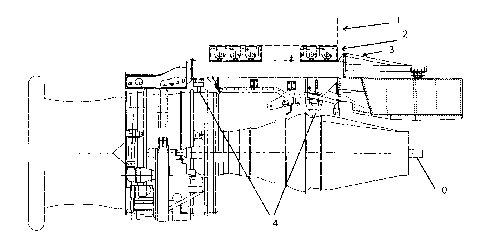
Figure 1 represents a schematic view of a test bed on which an engine such as
a
turbojet engine is inspected.
Figure 2 represents a cross section view of a constituent member of a
suspension
according to the present invention.
Figures 3a and 3b represent sets of several modules constituting a suspension
according to the present invention.
DESCRIPTION OF A PREFERRED EMBODIMENT OF THIE INVENTION
Figure 1 represents a portion of the test bed which corresponds essentially to
a
structure 3 which is the support structure for the engine to be tested, while
the fixed frame
1 of the test bed itself is represented only schematically.
This engine support structure 3 must be deform~able and able to withstand any
possible impacts, in particular in the case of behaviour under problematic
conditions. For
example, this structure must be able to withstand the load produced by the
breaking of
a blade of the turbojet engine.
The engine to be studied, for example a turbojet. engine 0, is fixed to the
engine
support structure 3 and held there by fastenings 4.
The present invention aims to propose, as a device for connecting between the
engine support structure 3 and the test bed frame, a modular suspension 2.

CA 02337739 2001-02-22
6
By virtue of this type of suspension, the natural vibrations of the engine and
of
the engine support structure 3 will be dissociated rather than transmitted to
the test bed,
both when running normally and when running under problematic conditions (such
as the
breaking of a fan rotor blade or the blocking of the rotor;l.
In addition, this solution makes it possible in a particularly advantageous
manner
to treat the fastenings 4 of the engine 0 to the engine support structure 3
moderately.
Figure 2 represents a cross section view of a constituent member of such a
suspension.
This member 20 advantageously has elastic behaviour and comprises an
elastomeric block 21, which is preferably cylindrical in shape and is more
particularly in
the shape of a bush. This member is hollowed at its centre and is arranged
around a
nozzle 22 and enclosed in a metal collar 23 which allows the said elastomeric
block 21
to be protected against an occasionally aggressive environment.
The said nozzle 22 is then force-fitted onto two independent axles 24 and 25.
The Figures 3 represent a set of several modules constituting a suspension
according to the present invention. Figure 3a represf;nts a six-module
suspension,
whereas Figure 3b represents a four-module suspension.
In Figure 3a, three modules 110, 120 and 130 are represented in full, whereas
for
the three modules 140, 150 and 160, only the member providing the elastic
function is
represented, which is the block of elastomeric material covered by its sheath
143,153 and
163. Each of these members is made up as represented iin Figure 2.
In order to allow the said suspension to be attached, on the one hand, to the
fixed
frame of the test bed, and, on the other hand, to the engine support
structure, a fixing
member 116, 126, 136, etc. or 117, 127, 137, etc. is provided, as represented
for the
modules 110,120 and 130, this fixing member fitting onto each axle or shaft
(not visible)

CA 02337739 2001-02-22
7
of the member providing the elastic function 111, 121 and.131 (not visible).
It is a totally
solid attachment with no degree of freedom of movement of the axles.
Moreover, the member providing the elastic function, consisting of the block
of
elastomeric material 11,12,13 (not visible), is itself enclosed in two fixing
half members
118 and 119, 128 and 129, 138 and 139, etc.
In Figure 3b, the four modules have been represented in full.

Representative Drawing
A single figure which represents the drawing illustrating the invention.
Administrative Status

2024-08-01:As part of the Next Generation Patents (NGP) transition, the Canadian Patents Database (CPD) now contains a more detailed Event History, which replicates the Event Log of our new back-office solution.

Please note that "Inactive:" events refers to events no longer in use in our new back-office solution.

For a clearer understanding of the status of the application/patent presented on this page, the site Disclaimer , as well as the definitions for Patent , Event History , Maintenance Fee  and Payment History  should be consulted.

Event History

Description Date
Application Not Reinstated by Deadline 2007-02-22
Time Limit for Reversal Expired 2007-02-22
Inactive: IPC from MCD 2006-03-12
Inactive: Abandon-RFE+Late fee unpaid-Correspondence sent 2006-02-22
Deemed Abandoned - Failure to Respond to Maintenance Fee Notice 2006-02-22
Letter Sent 2003-04-24
Reinstatement Requirements Deemed Compliant for All Abandonment Reasons 2003-04-02
Deemed Abandoned - Failure to Respond to Maintenance Fee Notice 2003-02-24
Inactive: Cover page published 2001-09-20
Application Published (Open to Public Inspection) 2001-09-17
Inactive: Compliance - Formalities: Resp. Rec'd 2001-08-28
Letter Sent 2001-08-24
Inactive: Applicant deleted 2001-08-22
Inactive: Incomplete 2001-08-21
Inactive: Correspondence - Formalities 2001-08-01
Inactive: Correspondence - Transfer 2001-06-22
Request for Priority Received 2001-06-22
Inactive: Courtesy letter - Evidence 2001-05-17
Inactive: IPC assigned 2001-04-25
Inactive: First IPC assigned 2001-04-25
Inactive: IPC assigned 2001-04-20
Inactive: Single transfer 2001-04-09
Inactive: Filing certificate - No RFE (English) 2001-03-26
Filing Requirements Determined Compliant 2001-03-26
Application Received - Regular National 2001-03-23

Abandonment History

Abandonment Date Reason Reinstatement Date
2006-02-22
2003-02-24

Maintenance Fee

The last payment was received on 2005-01-27

Note : If the full payment has not been received on or before the date indicated, a further fee may be required which may be one of the following

  • the reinstatement fee;
  • the late payment fee; or
  • additional fee to reverse deemed expiry.

Please refer to the CIPO Patent Fees web page to see all current fee amounts.

Fee History

Fee Type Anniversary Year Due Date Paid Date
Application fee - standard 2001-02-22
Registration of a document 2001-04-09
2001-08-28
MF (application, 2nd anniv.) - standard 02 2003-02-24 2003-04-02
Reinstatement 2003-04-02
MF (application, 3rd anniv.) - standard 03 2004-02-23 2004-02-05
MF (application, 4th anniv.) - standard 04 2005-02-22 2005-01-27
Owners on Record

Note: Records showing the ownership history in alphabetical order.

Current Owners on Record
TECHSPACE AERO S.A.
Past Owners on Record
GERARD GUILLET
ROBERT MALBROUCK
VINCENT MEIJNEN
Past Owners that do not appear in the "Owners on Record" listing will appear in other documentation within the application.
Documents

To view selected files, please enter reCAPTCHA code :


To view images, click a link in the Document Description column. To download the documents, select one or more checkboxes in the first column and then click the "Download Selected in PDF format (Zip Archive)" or the "Download Selected as Single PDF" button.

List of published and non-published patent-specific documents on the CPD .

If you have any difficulty accessing content, you can call the Client Service Centre at 1-866-997-1936 or send them an e-mail at CIPO Client Service Centre.


Document
Description 
Date
(yyyy-mm-dd) 
Number of pages   Size of Image (KB) 
Representative drawing 2001-09-07 1 15
Description 2001-02-22 6 245
Abstract 2001-02-22 1 18
Claims 2001-02-22 1 48
Drawings 2001-02-22 2 64
Drawings 2001-08-01 2 80
Cover Page 2001-09-20 1 41
Filing Certificate (English) 2001-03-26 1 162
Courtesy - Certificate of registration (related document(s)) 2001-08-24 1 137
Reminder of maintenance fee due 2002-10-23 1 109
Courtesy - Abandonment Letter (Maintenance Fee) 2003-03-24 1 179
Notice of Reinstatement 2003-04-24 1 167
Reminder - Request for Examination 2005-10-25 1 115
Courtesy - Abandonment Letter (Request for Examination) 2006-05-03 1 166
Courtesy - Abandonment Letter (Maintenance Fee) 2006-04-19 1 177
Correspondence 2001-03-26 2 23
Correspondence 2001-05-17 1 19
Correspondence 2001-06-22 4 99
Correspondence 2001-08-14 1 19
Correspondence 2001-08-01 2 69
Correspondence 2001-08-22 1 16
Correspondence 2001-08-28 2 84
Fees 2003-04-02 1 35
Fees 2004-02-05 1 33
Fees 2005-01-27 1 32