Note: Descriptions are shown in the official language in which they were submitted.
CA 02337764 2005-04-22
APPARATUS AND METHOD FOR HANDLING WASTE
BACKGROUND OF THE INVENTION
This invention relates to an apparatus and method for handling waste. More
particularly, but not by way of limitation, this invention relates to a system
for handling a
discharge of waste in a safe and environmentally protected fashion.
The discharge of waste, particularly from the drilling of an oil and gas well
for ultimate
production, presents many environmental problems. For instance, when a welt
bore is drilled
into the earth, the well may extend for many thousands of feet. During the
drilling process,
the well bore will be filled with a drilling fluid. The drilling iEluid is
necessary for several
reasons including pressure control, and lubrication of the driill string.
Thus, the drilling fluid is an essential component of t:he drilling process.
The physical
and chemical composition of the drilling fluid will vary. However, many times
the fluid
contains hazardous materials such as oil. Also, the drilling fluid will
contain solids which
comprise rock and shale cuttings. The volumes thus discharged, coupled with
the weight of
the cuttings, is very significant.
An important number of environmental regulations pertaining to the removal,
handling
and treatment of this fluid has been promulgated over the years. The
transferring of the
drilling fluid from on-site holding tanks (also known as pits) to vehicles
capable of
CA 02337764 2001-12-06
_ ~,4 9/ ib 23 5
~~~, ~M~ s ~ ~ P zooc~
hauling the waste creates the significant possibility of spillage. 'Thus, the
handling of the
drilling fluid so that the drilling fluid is disposed properly is a major
issue for companies.
Many type of prior art systems have been attempted to cure this problem, all
with limited
success. The invention herein disclosed solves these problems by disclosing a
system and
method of handling environmental waste in a safe and economical process. It
should be
noted that the invention herein disclosed is also applicable to other
industries wherein the
handling of waste for transportation to and finm sites is necessary.
SUMMARY OF THE INVENTION
An apparatus for handling a waste material is disclosed. Generally, the
apparatus
comprises a container having disposed thereon a rail member. 'fhe apparatus
also contains a
car mounted on the rail. The car will have extending therefrom a first wiper
that extends into
the container. The apparatus may also contain an auger means, operatively
mounted on the
container, for removing the waste from the container.
In one embodiment, the wiper (also referred to as a shovel) comprises an
elongated
member having a first end and a second end, with the second end being
pivotally mounted to
the car. 'The apparatus may further comprise an oscillating means for
oscillating the wiper.
Also included will be transporting means for transporting the car via the rail
from one end of
the container to the other.
Generally, the waste contained within said container consist of a slung
comprising: a
2
CA 02337764 2001-12-06
r~ - ~ '~' ~ ~~6~ 4e~
~~ ~~ 6 ~ ~ P 2400
fluid; solids suspended in the fluid; and solids. The waste may be a
discharged drilling fluid
from a well bore. It should be noted, however, that the invention herein
disclosed is
applicable to other types of waste which contains fluids, solids suspended in
fluid, and solids.
The apparatus may further comprise pump means, operatively associated with the
wiper, for
pumping the fluid and solids suspended in the fluid from the container.
10
In another embodiment, the shovel comprises a first blade member attached to
the
elongated member at the first end, and a second blade member also attached to
the elongate
member at. the first end. In this embodiment, the first blade member is
positions in a first
direction relative to the container and the second blade member is positioned
in a second
dirxtion relative to the container. Thus, waste can be shifted to one end of
the container by
the 5rst blade member; alternatively, movement in the orposite direction will
shift the waste
to the opposite end of the container by the second blade.
A process for handling a discharge waste slurry is also disclosed. In the
preferred
embodiment, the waste slurry is a drilling fluid discharge from a drilled bore
hole. The
process iucludes placing the discharge waste slurry into a container. In this
embodiment,
the container contains: a rail; a trolley positioned on the rail; a pump means
for pumping the
discharge. waste slurry from the container; a shovel means, operatively
associated with the
trolley, for shoveling the discharge waste slurry from a first position within
said container to
a second position within the container.
CA 02337764 2001-12-06
p~~ g9/ 1635
2 6 SEP 2000
The process fiuther includes transporting the tmlley from a first position to
a second
position. The pump means can pump the dixhargod waste slurry from the
container. In one
embodiment, the shovel means contains an elongated member capable of pivoting.
The
process further comprises pivoting the shovel means in a swinging fashion, and
thereafter,
stirring the discharge waste slurry. The pump means can withdraw the waste
slurry from the
container so that the container is emptied.
Th<; process may fiurther comprise the steps of terminating the pumping, and
thereby
allowing the waste to separate into a mostly fluid phast and a solid phase.
Thereafter, the
operator would adjust the physical level of the pump means so that the pump
coincides with
the level a:f the fluid phase. Next, the operator would pump the waste from
the container.
T'h~e process may also include transporting the trolley from a first position
to a second
position on the rail. Thus, the shovel means would push the solids to the
second position
within the container. The container may further include an auger positioned at
the second
position. 'Therefore, the process further comprises the steps of removing the
solids from the
container with the aid of the auger.
A second embodiment of the present invention, which is the preferred
embodiment of
this application, is also disclosed. This second embodiment includes a system
for handling
waste material comprising a tank containing the waste material and a
reciprocating carriage
operativelly associated with the tank. The reciprocating carriage will have a
handling member
4
CA 02337764 2001-12-06
PCTI9 9 / 16 ~~ 5
~!~~ 2 6 S E P zQ4Q
adapted thereto, with a pump means, operatively associated with the handling
member, for
pumping t~~e waste material from the tank. The system will also contain an
auger, positioned
within the tank, that is adapted to convey the waste material from the tank.
In one embodiment, the handling member has a first tnd pivotly attached to the
reciprocating carriage, and the second end has disposed therewith a pmcess
device. A
reciprocating means is operatively associated with the handling member so that
the elongated
member may be pivotal within the tank. Generally, the process device is a
vertically oriented
auger attached to the handling member. Also, the system may include a slurry
gate
operatively associated with the pump means and adapted to receive the waste
material
discharged from the process device. In the preferred embodiment, the process
device
contains a vertically oriented spiral blade.
Also disclosed is an impeller means, operatively associated with the pump
means, for
loading the pump means. ''1"he impeller means may comprise a series of rotor
blades mtatably
mounted. beneath the pump. The rotor blades may contain a vertically oriented
plate mtmber,
with the plate member having a concave surface formed therewith that aids in
channeling the
2,0 waste into the pump. Additionally, the process device may contain a
plurality of teeth
adapted to the spiral blade of the process device. The process device may be
detachably
construed with the handling member for selective detachment.
The second embodiment also discloses a process for handling waste materials.
.5
CA 02337764 2001-12-06
~I~9/~b~35
~~~~~ ~ a S EP 204Q
Generally, the process comprises placing the waste material within a system.
The system will
comprise a ~tanlc containing the waste material; a reciprocating carriage
having a handling
member adapted thereto; a pump means for pumping the waste material firm the
tank; a first
auger, positioned within the tank, adapted to convty the waste material finm
the tank, and
wherein the first end of the handling member is pivotly attachod to the
reciprocating carriage.
Next, the process includes transporting the carriage from a first position to
a second
position, and the drilling fluid waste is pumped from the tank. The operator
will terminp~te
the pumping and allow the waste to separate into a solid phase and a liquid
phase. 'Thereafter,
the operator will transport the carriage from a first location of the tank to
a second location of
the tank so that the solids phase is pushed to the second side of the tank,
and thereafter,
removing the solid phase from the tank with the first auger.
The system may further comprise pivoting means adapted to pivot the elongated
member frnm a first position to a second position, and thus, the process
further comprises
pivoting tbie elongated member from the first position to the second position
so that the
drilling fluid waste is stirred.
It should be noted that the process may include channeling the waste to a
process
device, and thereafter, conveying the waste to the pump means via the process
device. Next,
the operator would transport the carriage from a first side of the tank to a
second side of the
tank so tluit the solid phase is pushed to the second side of the tank. The
solid phase can then
6
CA 02337764 2005-04-22
be removed from the tank with the first auger.
The pump means may include an impeller assembly operatively attached thereto,
and
with this embodiment, the process further comprises rotating the impeller
which in turn
channels the waste with the rotating impeller so that the pump is loaded.
In another embodiment of this invention, which is tire most preferred
embodiment of
the application, a system for handling a waste material is di;:closed. The
system includes a
tank that contains waste material and a reciprocating caa~~rriag;e that is
operatively associated
with the tank. The reciprocating carriage will have a handling member adapted
thereto. A
process device is attached to the reciprocating carriage, with the process
device comprising a
base having a first blade member extending radially therefrom. The blade
member is adapted
to channel the waste material downward.
The system further consist of a pump means operatively associated with the
handling
member, for receiving the waste material from the process device and pumping
the waste
material from the tank. The pump includes a first rotor blade and a second
rotor blade
positioned for loading the pump means. The first rotor blade and second rotor
blade may
include a first and second vertically oriented plate member, with the first
and second plate
rriem~er having a concave surface forming a scoop thereon that is adapted to
deliver the
waste material into a pump inlet.
a
CA 02337764 2001-12-06
PG'~I'~ 9 '~ I 1
r~"'~". Q
. , z~ .~ ~ ~~
The systtm may further comprise a motor operatively associated with the
handling
member so that the handling member may be pivoted within the tank. A slurry
gate may also
be includodl that is operatively associated with the pump means and adapted to
receive the
waste material channeled dawnward from the process device. A second blade
member may
be included that extends radially from the base. The second blade member is
oriented in a
plane opposite the first blade member and is configured to channel the waste
material
downward.
In the preferred embodiment, the first rotar blade and the second rotor blade
are
oriented in the opposite planes above the pump inlet. A third flat plate and a
fourth flat plate
may also be included, with the flat plates being oriented in oppasite planes.
The system may
further comprise a third blade member and a fourth blade member extending at
an angular
direction Erom the base so that the third blade member and the forth blade
member are
adapted to channel the waste material downward. In this embodiment, the
angular direction
is at least 10 degrees.
According to the teachings of the present invention, the process device may be
detachable from the handling member. Also, the first blade member, second
blade member,
third blade member and fourth blade member comprise a shaft having a first end
and a second
end, and wherein the first end is connected to the base, and the second end is
connected to a
paddle head. The paddle head may be offset relative to the shaft at an angle
of deflection of
at least 90 degrees.
g
CA 02337764 2001-12-06
P~?'~ 99/ ib~~5
,~,~~2 ~ ~ ~ ~ 200
In the most preferred embodiment of this application, a process for handling a
drilling
fluid waste from an oil and gas well bore is also disclosod.. The proctss
generally comprises
placing a drilling fluid waste within an apparatus. The apparatus consist of a
tank, a
reciprocating carriage operatively associated with the tank, the recipmcating
carriage having
a handling member adapted thereto, with a pump means, operatively associated
with the
handling member, for pumping the drilling fluid waste from the tank. A process
device,
which is attached to the handling member, is orientated in a first plane. The
process device
includes a base having a first blade member and a socond blade extending
radially therefrom.
The: process includes transporting the carriage from a first position to a
second
position and rotating the base of the process device so that the drilling
fluid waste is directed
downward with the first blade paddle head and with the second blade paddle
head. The
impeller will be rotated, with the impeller containing a first rotor blade and
a second rotor
blade posiraoned for loading the pump means via the inld. The first rotor
blade and second
rotor blade; comprise a first and second vertically oriented plate, with the
first and second
plate having a concave surface forming a scoop thereon and adapted to deliver
the waste
material into a pump inlet.
The process fiuther consist of pumping the waste from the tank, and thereafter
terminating the pumping. 'rhe operator will allow the drilling fluid waste to
separate into a
solid phase and into a liquid phase, and transport the carriage firm the
second position to a
third position. The removal of the solid phase from the tank with the pump
means may
9
CA 02337764 2001-12-06
PI~9/16~35
~~~,~~ ~ ~ ~P 2000
thereafter continue.
The process would then include pivoting the handling member from the first
location
to the second location and stirring the waste. The process would further
entail transporting
the carriage: from a first side of the tank to a second side of the tank so
that the solid phase is
pushed to dhe second side of the tank. The solid phase may then be removed
from the tank
with the pump means. In one embodiment, a plurality of impeller members are
rotated which
in tum allows for accumulation of the waste within the scoops which in turn
loads the waste
into the inlet of the pump means.
A pump member is also disclosed. The purnp member will include a motor having
a
shaft extending therefrom. A pump case having an inner cylindrical chamber is
also
included. The inner cylindrical chamber will receive the shaft. A circular
base is positioned
within the inner cylindrical chamber, with the shaft being attached to the
center of the base.
The pump member also contains a first plate member and a second plate member
extending vertically from the circular base. In ane embodiment, the first
plate member and
the second plate member are disposed in radially opposing planes about the
center. In the
preferred embodiment, a fist tail section extends from the first plate member
and a second
tail section extends from the second plate member. The first tail section and
the second tail
section can protrude outward from the opening. A disposal conduit is also
included, and
wherein th.e conduit extends finm the pump case and is fluidly connected with
the inner
l t7
CA 02337764 2001-12-06
.~,._...., 9 g ~ ~b 23 ~
:~"'~~~' '4:~
cylindrical chamber,
The pump may further comprise a third plate member and a fourth plate member
extending vertically from the circular base. Generally, the third plate member
and the fourth
plate member are disposed in radially opposing planes about the circular base.
Further, the
first tail section and the second tail section contain concave surfaces
forming a first scoop on
the first taili section and a second scoop on the second tail section. A
process device may be
included with the pump, with the process device adaptod to channel waste to
the pump inlet.
An advantage of the present system is that the operator may remove tons of
environmental waste from a site without spillage to the surrounding area.
Another advantage
is that the invention combines the concept of a backhoe, pump, dozen and
process device into
a complete operable system.
Yet another advantage is that the present invention saves an operator time
since in the
past it was required to separately utilize the referenced components in order
to adequately and
safely handle the waste. Still yet another advantage is that the system herein
disclosed will
produce the operator significant savings.
An. advantage of the second embodiment of the present invention includes use
of a
vertical auger that causes the slurry to be channeled downward. Another
advantage is the
vertical auger will shred, dissipate and disperse the solids into smaller
particles that have
11
CA 02337764 2001-12-06
-~~~I'y ~ / 16 2 3 ~
"~ 2 ~ ~ E P 2000
S better flow properties and/or may be suspended in the fluid phase. Yet
another advantage is
that the im~,peller will serve to agitate solids and/or suspend solids in the
fluid phase.
Still yet another advantage is the impeller will effect a positive
displacement to the
pump by clhanneling and loading the waste into the pump inlet. In other words,
the system
will also have the advantage of force feeding the slurry into the pump via the
impeller. Yet
another advantage is the slurry gate cooperating with the vertical auger and
pump impeller to
accept the channeled slurry into the pump inlet.
An advantage of the third embodiment includes use of the cutter head that will
shred,
dissipate and disperse the solids into smaller particles that have better flow
properties and/or
may be suspended in the fluid phase. Yet another advantage of the cutter head
is the ability
to channel and direct the waste downward to the pump inlet.
A feature of the present invention includes use of a mobile trolley mounted on
a rail
system contained on the container with a motor means. Another feature includes
a handling
system operatively associated with the trolley. Another feature includes a
handling system
containing a shovel, backhoe, pump, and pivoting means mounted thereon.
Ye;t another feature includes an auger to remove accumulated solids within
container.
Still yet another feature includes a shovel that may function as wiper,
stirrer, or spade.
Another feature includes use of a pump that may be varied in position to
accommodate the
1 ~!
CA 02337764 2001-12-06
z
.. .~,~~1~ ~ S E P 410
varying lcwels of waste, as well as the composition of the waste, within the
container.
Another feature includes operation of the handling system and trolley from a
remote location.
A feature of the second embodiment includes use of a detachable process device
such
as a vertical auger. Another feature includes having a plurality of teeth
placed on the vertical
auger blades. Yet another feature includes use of a slung gate that may be
manually operated
or closed. The rotatable blades of the impeller is yet another example of a
feature of the
present invention.
Another feature of the third embodiment includes having paddle heads that will
cut,
shear and :>ever the waste. Another feature of this embodiment includes having
some blades
vertical in relation to the ground level while another set of blades are
inclined relative to the
I 5 vertical blades. Still yet another feature includes the cutter head
directs the waste downward.
The cutter head will shred, dissipate and disperse the solids into smaller
particles that have
better flow properties and/or may be suspended in the fluid phase.
Still yet another feature of the third embodiment is the rotor blades having
the
concave scoop that is radially adjacent the pump inlet to load the pump.
Another feature is
the use of vertical plates coupled with the rotor blades in order to load the
pump. Still
another feature is that in this third embodiment, there are two rotor blades
that are radially
opposed to each other about the pump inlet. Yct another feature is that two
vertical plates are
included, with the two vertical plates being radially opposed to each other
about the pump
13
CA 02337764 2001-12-06
~r~-' ~ ~,~ ~b ~ ~ 5
~f~i ~ sE~ zao~
inlet.
BRIEF DESCRIPTION OF THE DRAWINGS
FIGURE I is an illustration of the first embodiment of the apparatus including
the
container, trolley and haadling systan, with the handling system being in a
first position.
FIGURE 2 depicts the apparatus of FIGURE 1 with the handling system in a
second
position.
FIGURE 3 is a schematic side view illustration of an embodiment of the
handling
system
of the first embodiment.
FIGURE 4 is a schematic front view illustration of the handling system of
FIGURE
3.
FIGURE 5 depicts the schematic side view illustration of the handling system
of
FIGURE 3 in various positions within the container.
14
CA 02337764 2001-12-06
P~fl~9 9 ! 16 ~ 5
' ~~~ 2 6 S E P 2 00
FIGURE 6 is an illustration of the second embodiment of the apparatus
including the
container, urolley and handling system, with the handling system being in a
first position.
FIGURE 7 is a perspective view of the first embodiment of the impeller device.
1~ ICiURE 8 is a top 'view of the impeller device of FIGURE 7.
FIGURE 9 depicts the schematic side view illustration of the handling system
of
FIGURE 6 in various positions within the container.
FIGURE 10 is a front view illustration of the cutter head member of the
present
invention.
FIGURE 11 is the side view of the cutter head member of FIGURE 10.
FIGURE 12 is a perspective view of the cutter head member of FIGURE 10.
FIGURE 13 is a side view of the second embodiment of impeller device.
FIIGURE 14 is an upper view of the impeller device of FIGURE 12.
FIGURE 15 is a perspective view of the impeller device of FIGURE 13.
CA 02337764 2001-12-06
P~CT'99/ ibZ3~
~~2'S SEP ?.QQQ
FI(~UR,E 16 is an illustration of the third embodiment of the apparatus
including the
container tmolley and handling system, with the handling system being in a
first position.
FIGURE 17 is a perspective view of the pump member of the preferred embodiment
of the present application.
FI<rURE 18 is the lcont view of the pump member of Fig. 17.
FItJURE 19 is the underside view of the pump member of Fig. 17 depicting the
impeller.
FIIsURE 20 is a cut through view of the preferred embodiment of the impeller
within
the pump ease of Fig. 17.
FhGURE 21 is a cress-sectional view of the pump including the impeller of the
preferred embodiment taken along line "21" of Fig. 19.
FIGURE 22 is a perspective view of the fourth embodiment of this invention
that
includes a plurality of cutter heads mounted to a pump.
FIGURE 23 is a top view of the embodiment of FIGURE 22.
1 ti
CA 02337764 2001-12-06
1
~~~.~ ~,'~'~~.'~a' ~ 6 SEQ ~~
DESCRLr.'~'ION t,~~ THE PREFERRED EMBODIMENTS
Referring now to Fig. l, an illustration of the apparatus 2 including the
handling
system 4 and auger 6, will now be described. Generally, the apparatus 2
includes a container
8 that in the preferred embodiment of an elongated tank member capable of
holding the
waste. T'he container 8 contains a first end 10 and a second end 2 with a
bottom 14 and an
open top cnd ~,ø. As depictod in Fig. 1, the width of bottom 14 is gcncrally
narrower than the
open top end 16 so that the movement of the waste within the container 8 may
be facilitated,
as will be more fully set out later in the application.
T'h.e container 8 is designed so that it can be easily transported from
location to
location. 'Thus, the container 8, slang with the handling system 4 and auger 6
may be used on
land locations, or alternatively, may be transported and placed on offshore
platform or other
remote locations.
T'he container 8 has contained thereon a pair of rails 18 that are mounted
onto the
container 8 by means of support braces 20. As shown in Fig. 1, the rails 18
transverse the
open top of 16. It should be noted that while a pair of rails 18 has been
depicted, a single rail
member is within the scope of this invention.
T°he pair of rails 18 will have operatively associated therewith the
handling system 4.
1~
CA 02337764 2005-04-22
The handling system 4 is mounted on a platform 22 with tlhe platform having a
set of wheels
24. The platform 22 may also be referred to as thetrolley ~!2. The platform 22
will also
contain a pair of sprocket wheels 26 which are propelled by a motor means,
which will be
described.later in the application, so that the handling system is moved back
and forth from
the first end 10 tv the second end 12 as desired by the operator. The sprocket
wheel 26
projections fit within and engaged with the tracks 80 for traction.
The handling system 4 will have extending into the container 8 a shovel means
28
operatively associated with the platform 22, for transporting the waste fi-om
one end 10 to the
other end 12 of the container. Alternatively, the shovel means 18 may be used
to stir the
waste contained within the container 8. The handling systc;m 4 will also have
associated
therewith a pump means 30. operatively associated with the sho~wl means 28,
for pumping
the waste from the container 8. It should be noted that throughout the
application, like
numbers in the various figures refer to like components.
Refeciing now to Fig. 2, the apparatus 2 of Fig. 1 LS illustrated wherein the
trolley 22
and handling system 4 has been moved to a second position. The transporting of
the handling
system 4 is controlled by activating the motor so that the sprocket wheels 26
revolve so that
the trolley 22 (via the wheels 24) is mov~i. The shovel means 28 will also
travel within the
container 8. The shovel means 28 is held in a rigid position, perpendicular to
the bottom 14.
Thus, the waste within the container is pushed to the end :12. At this point,
the auger 6 may
be activated in order to transport the waste from the container 8.
18
CA 02337764 2005-04-22
As seen in Fig. 3, an expanded view of the handling; system 4 will now be
described.
As illustrated, the trolley 22 has attached thereto the wheels 24 which are
positioned on the
track 18. Also associated with the trolley 22 is the sprocket wheels 26 which
are driven by a
motor means 38 for propelling the sprocket wheels 26.
The shovel means 28 will have associated therewith a boom ladder number 40
with
the boom ladder member 40 extending from an extension member. The boom member
40
and the extension member 42 are pivotally attached by conventional means such
as by pin 44.
The extension member 42 is attached to the platform 22.
The boom ladder member 40 will have attached thereto an extension member 46.
with
the extension member in turn having a shovel blade 48. As, depicted in Fig. 3,
the shovel
blade 48 is tilted at an angle relative to the bottom 14 container 8. Also
depicted in Fig. 3 is a
detachable shovel blade 50 which in turn is attached to the 'boom member 40
via the
extension member 52 with the detachable shovel blade 50 facing in an opposite
plane with
respect to the shovel blade 48. Thus, in operation as the handling system 4 is
moved from a
first position to a second position and then back to the first position, the
shovel blade 50 can
act to shovel the waste in a second direction. In an alternative embodiment,
the detachable
shovel blade 50 need not be connected.
The handling system 4 has included therewith a pump means 30 which includes
the
pump motor 54 which in tum is adapted to the pump case cylinder ~6. A guard 58
is also
19
CA 02337764 2005-04-22
included so that the suction inlet 60 is raised enough off the bottom so that
large solids do not
enter the pump or block o~the suction inlet 60. A disposal conduit 62 leads
from the pump
cylinder 56 so that the siphoned waste will lead to the swivel joint conduit
64 for ultimate
disposal.
Also included will be a plate 66 aiding in the attachment of the boom ladder
member
to the handling system 4, and associated therewith will be bottom rollers 68
which aids in
keeping the platform 22 on the track 18. The handling system 4 will also
include the
oscillating means 70 for oscillating and pivoting the boom ladder 40.
Generally, the .
oscillating means 70 contains a pair of hydraulic cylinders T2 that have a
cooperating pair of
hydraulic cylinder rams 74. The oscillating means 70willbe operatively
connected to a
hydraulic line system 76. with the line system 76 being long enough so that as
the handling
system travels along the rail 18, the Line system ?6 will extend the proper
distance. Also,
back and forth movement of the trolley 22 along the rail 18 is possible.
Referring now to Fig. 4, a front elevation of the handling system 4 is shown.
In the
preferred embodiment, the boom member 40 has a first leg ~40a and a second leg
40b. with the
support braces 78 also being included. Also depicted in Fig. 4 is the
cooperation of the
wheels 24 and the bottom rollers 68 with the rail 18. Additionally, the
oscillating means 70 is
depicted with the swing cylinders 72 that lead to the hydraulic cylinder rams
74.
Fig. 4 also depicts the means by which the handling system 4 travels along the
rail
CA 02337764 2005-04-22
andtrack 80. More particularly, the sprocket wheels 26 are adapted for
engagement with the
track 80, with the track 80 being capable of receiving the sprocket
projections.
Referring now to Fig. 5, the operation of the invention will now be discussed.
As
shown, the handling system 4 has the boom ladder 40 extended perpendicular
relative to the
bottom 14 in the position designated by the letter (A). In the illustration of
Fig. 5, the
container 8 has a waste disposed therein. More particularly, the waste has two
different
phases, namely: (1) a mostly liquid phase with solids disposed therein; and,
(2) a mostly solid
phase with a liquid disposed therein.
Thus, with the boom 4.0 in the position as representative by (A), the operator
may
activate the motor means so that the sprocket wheels 26 rotate which in turn
moves the trolley
22 and handling system 4 forward on the rails 18. As the handling system moves
forward,
the shovel blade 48 will heap the waste in the direction of the auger 6 for
removal by the
auger 6. Alternatively, the operator may reverse the direction of the handling
system 4 so
that the detachable shovel blade 50 will heap the waste in the opposite
direction of travel.
The operator may also kick on the pump means 30 to suction off accumulated
liquid during
24 this process. This can continue at the discretion of the operator until the
container 8 is
properly emptied.
As an alternate means of operation, the operator may pivot the boom ladder
member
40 as shown in the position (B) of Fig. 5. This is accomplished by activating
the hydraulic
21
CA 02337764 2001-12-06
P'CfA~ 9 9 / 16 ~ ~ ~
~~ ~ ~ s E P zo~a
S cylinders to that the hydraulic hams pivot the boom ladder member 40. If
desired, the
position (~3) corresponds with a level that places the suction point 60 within
the fluid (F)
phase.
At the position shown in (B), the pump means 30 may be activated which in turn
will
suction thE; fluid (F) phase W to the disposal conduit 62. Of course, if so
desired by the
operator, the sprocket wheel 26 may be activated which in turn would cause the
handling
system 4 t~o travel via the nails 18. 'Thus, the waste would also be stirred
by such action. An
oscillating; movement of the boom 40 may aid in stirring the waste, or
alternatively, dislodge
unwanted piles of solids that have built up within the container 8.
As. yet another alternate means of operation, the operator may pivot the boom
ladder
1 S member 40 as shown in the position (C) of Fig. 5. This is accomplished by
activating the
hydraulic cylinders so that the hydraulic rams pivot the boom ladder member 40
backward
relative to position (B). Again, the position (C) may correspond with a level
that places the
suction point within the fluid (F) phase.
Therefore, the operator may activate the pump means 30 -- at the position
shown at
(C) - which in turn will suction the fluid (F) phase into the disposal conduit
62. The
handling aystem 4 may again be moved via the sprocket wheel 26. An oscillating
movement
of the boom 40 may aid in stirring the waste, or alternatively, dislodge
unwanted piles of
solids that have built up within the container 8. The movement of the boom 40,
handling
z2
CA 02337764 2001-12-06
~"
rr ~~~'~ ' ~ ~ ~r ,;~ :~ t~. ;a ~
tP~2 ~ S E P 2000
system 4 and activation of the pump means 30 is done by the ope:raior
depending on the
particular characteristics of the waste.
The boom 40, handling system 4, auger 6 and activation of the pump means 30
may
be controlled remotely from a site away from the container, or alternatively,
the control
system for the operator may be placed on the container.
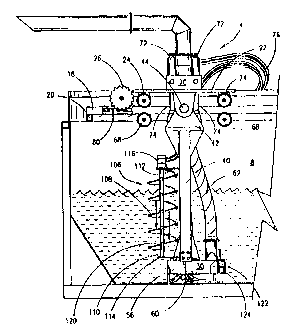
RelfercW g now to Fig. ~, an illustration of the second embodiment (which is
the
preferred embodiment of this application) of the apparatus 2 including the
container 8, trolley
22 and har,~dling system 4, with the handling system 4 being in a first
position, will now be
describe. It should be noted that like numbers appearing in the various
figures refer to like
components. Generally, the apparatus 2 is similar in construction to the first
embodiment.
I S Thus, platform 22 is operatively associated with the rails 18 situated
with the
container 8. As previously described, extending therefrom is the disposal
conduit 62 that is
operatively associated with the pump means including the pump motor 54 and
pump cylinder
S6. With the preferre apparatus 2, a process device 106 , which is the
preferred embodiment
is an auger, has been selectively attached to the boom ladder member 40. Thus,
the second
auger 106 will comprise a generally spiral blade 108 coiled about a center
mandrel 110. The
second auger 106 is rotatably attached via the supports 112 and 114, with the
supports being
detachably affixe to the b~~om ladder member 40. A hydraulic member 116 is
operatively
associated with the detachable secand auger 106 so as to power the detachable
auger 106 to
23
CA 02337764 2001-12-06
s;~';~ ~ r:~'
6 SEP
rotate.
The detachable sexond auger 106 will process the slurry by ble~ndmg, mixing,
and
dispersing the solids into tine fluid phase so that the slurry is more
manageable since the
slurry is more consistent. Also, the flow properties of the slurry are
significantly increased.
The second auger 106 will also act as a shovel andlor wiper since it tends to
collect the waste
so that the waste may be handled. The auger spiral blades 108 will also
contain upstanding
proje~ction:~ or teeth 120 that will aid in the ripping apart of the solids.
A.s shown in Fig. 6, the
auger lOfi will funnel the slurry downward towards the pump cylinder 56.
Also included with the present invention is the slurry gate 122 which is a
valve means
that has an open position and a closed position. In the embodiment shown in
Fig. 6, the
slurry gate;112 is a manually opened or closed gate. When the gate 122 is
opened, the inlet
124 will r~xeive the slurry and h~ansport the slung into the pump cylinder.
Alternatively, the
operator naay wish to have the slurry gate closed wherein the slurry would be
received in
pump inlet ,~ 26. The slurry gate 122 is configured to receive the slurry
being diseharge~ from
the auger 106 as wel! as rex:eiving the slurry from the bottom area of the
container 8 as shown
by the flow line in Fig. 6. The operator may deem it appropriate to close the
slurry gate,
when for instance, the detachable auger 106 has been detached and/or the
detachable auger
106 is nol: in use. The slurry gate 122 will have extendable arms 124 for
closing and opening
the gate 122..
24
CA 02337764 2001-12-06
r99~~~z3s
~~ ~ ~ ~ p 200
Also shown in Fig. 6 is the impeller member 126 that are configured at the
bottom of
the pump cylinder 56. The impeller member 126 is seen in Fig. 7 and comprises
a plurality
of blades :~, X30 1~2 that are rotatably mounted on the pump means. The
impeller blades
128, 130, and 132 are vertically ariented blades that extend from a horizontal
base plate ~4,
with the horizontal base plate 134 being operatively configured with the pump
inlet, with the
pump inlet being configured on the bottom of the pump cylinder 56. The
horizontal base
plate 134 contains the opening 136 which is operatively configured to be
connected to the
pump inlet.
Each of the blades 128, 130, 132 will be of similar construction. Thus, for
instance,
blade 128 will have a substantially flat plate 128A, with the plate 128A
having a first end
128B that is attached to the horizonal base plate 134 by conventional means,
such as welding.
The plate 128A will extend to the second end 128 with the end 128C containing
the curved
tail area _128D. The tail area 128D extends from the side radially adjacent
the opening 136.
As seen v1 Fig. 7, the tail area has a surface 128E and a surface 128F with
the surface 128E
being convex and surface 128F and being concave (in the preferred embodiment)
such that a
pocket ar scoop is formed thereon. The blade 130 will have a substantially
flat plate 130A,
with the plate 130A having a first end 130B that is attached to the horizonal
base plate 134.
The plate 130A will extend to the second end 130C, with the end 130C
containing the curved
tail area 1130D. The tail area 130I) extends from the side radially adjacent
the opening 136.
The tail area has a surface 130E and a surface 130F with the surfaces 140E
being convex and
surface 130F being concave (in the preferred embodiment) such that a pocket or
scoop is
CA 02337764 2001-12-06
P~'ff t~ 9 9 ~ 14 ~ 3 5
~'~J~ ~~~ SEP ?.04Q
formed the;neon. Also blade 132 will have a substantially flat plate 132A,
with the plate 132A
having a fu~st end 132B that is atta~chod to the horizonal base plate 134. The
plate 132A will
extend to the second end ~i2~" with the end 132C containing the curved tail
area 32D. The
tail area 132D extends from the side radially adjacent the opening 136. The
tail area has a
surface 1~ and a surface 1~ with the surface 13 E being convex and surface
132F being
concave (in the preferred embodiments such that a pocket or scoop is formed
thereon.
The Figs 7 and 8 also illustrate a side 1286, 1306. and 1326 that has been
added.
The sides 1286, 1306, 1326 generally extend perpendicularly away from the
surface 128F,
130F, and 132F respectively. The sides 1286, 1306 and 132Cr form a cup section
on the
blades in 'the preferred embodiment.
A;s can be seen by the arrow 13 which depicts the rotation of the impeller,
the
rotation i.s such that the concave surface 128F in combination with the plate
surface 128A
will act to funnel the waste into the opening l3ti. The action of concave
surfaces 128F, 130F,
and 132F will create a positive displacement of the waste into the pump. The
centrifugal
action of the blades 128, 130 and 132 forces the waste into the opening 136
which
significa~atly aids in the elficicncy of the pump means and the evacuation of
the waste from
the container. In other words, the rotation of the blades 128, 130 and I 32
aids in the creation
of energy necessary to fiumel the waste into the pump inlet. Also, when the
blades 126 are
energized, the rotation wi ll agitate and blend the slurry to a preferred
consistency that will
better enable the slurry to be pumped into the pump cylinder 56. Fig. 8 has
also been
26
CA 02337764 2001-12-06
~:~~ ~ ~ ~a ~~~
'~~,~'~~ ~ 6 CEP
included to depict the top v2ew of the impeller member 126.
Referring now to Fig. 9, the operation of the invention depicted in Fig. 6
will now be
discussed. As shown, the handling system 4 has the boom ladder 40 extended
perpendicular
relative to the bottom 14 in the position designated by the letter (A). In the
illustration of Fig.
7, the container 8 has a waste disposed therein. More particularly, the waste
has two different
phases, namely: (1) a mostly liquid phase with solids disposed therein; and,
(2) a mostly solid
phase witk~ a liquid disposed therein.
Thus, with the boom 40 in the position as representative by (A), the operator
may
activate th.e motor means so that the sprocket wheels 26 rotate which in turn
moves the trolley
22 and ha~~dling system 4 forward on the rails 18. As tile handling system
moves forward,
the auger 106 will also be rotating. Therefore, the auger 106 will funnel the
waste in the
direction of the slung gate 122 for channeling into the pump cylinder 56 to
suction off the
slurry via pump means 30. The operator may reverse the direction of the
handling system 4
so that the; handling system 4 travels in an opposite direction thereby
traversing the container
bottom 144. This can contirme at the discretion of the operator until the
container 8 is properly
emptied.
As an alternate means of operation, the operator may pivot the boom ladder
member
40 as shown in the position (B) of Fig. 7. This is accomplished by activating
the hydraulic
cylinders so that the hydraulic rams pivot the boom ladder member 40. If
desired, the
2'7
CA 02337764 2001-12-06
~~:ih~ 9 y! ~tb~~~
~~2 s ~ E P 2~0
position (B) corresponds with a level that places the suction point 60 within
the fluid (F)
phase.
At the position shown in (B), the pump means 30 may be activated which in tam
will
suction the fluid (F) phase into the disposal conduit 62. The auger 106 may be
activated so
that slurry may be funneled thmugh the blades 108. Even though the inlet 124
may be in the
fluid phase, since the slung will still contain some solids, the action
through the auger 106
will only nd in the blending of the slurry for a better slurry consistency for
pumping and
discharge. As with the operation of the first embodiment (As seen in Fig. 5),
the sprocket
wheel 26 may be activated which in tam would cause the handling system 4 to
travel via the
rails 18. ';Chas, the waste would also be stirred by such action. A.n
oscillating movement of
the boom 40 may aid in stirring the waste, or alternatively, dislodge unwanted
piles of solids
that have built up within the container 8.
As yet another alternate means of operation, the operator may pivot the boom
ladder
member 40 as shown in the position C of Fig. 9. This is acxomplished by
activating the
hydraulic cylinders so that the hydraulic rams pivot the boom ladder member 40
backward
relative to position (B). Again, the position C may correspond with a level
that places the
suction point within the fluid (F) phase.
Therefore, the operator may activate the pump means 30 -- at the position
shown at C
-- which in tunn will suction the fluid (F) phase into the disposal conduit
62. The handling
28
CA 02337764 2001-12-06
P~'f99/ ib~35
~~2 s s E P zoos
S system 4 rnay again be moved via the sprocket wheel 26. An oscillating
movemtnt of the
boom 40 rnay aid in stirring the waste, or alternatively, dislodge unwanted
piles of solids that
have built up within the container 8. The movement of the boam 40, handling
system 4 and
activation of the pump means 30 is done by the operator depending on the
particular
characteri;>tics of the waste
The boom 40, handling system 4, auger 6 and activation of the pump means 30
may
be controlled remotely from a sift away from the container, or alternatively,
the control
system for the operator may be placed on the container.
Referring now to Fig. 10, a second embodiment of a process device 15Q will now
be
described, with the process device 150 being referred to as a cutter head 150.
The cutter head
L S 1 SO comprises a generally cylindrical base member 152, with the base
member 152 being
operatively attached to the pump housing 56 in one embodiment. The base member
152 will
rotate about the connection point 154.
T'he base 152 will have a plurality of blades radially extending therefrom,
namely
blades 156. 158. 160, 162. 164. 166. These blades (1S6-166) generally contain
a shaft 168
having a first end 170 and a second end 172, with the first end 170 being
attached to the base
152. T'he second end 172 will have operatively attached thereto a paddle head
174. As
depicted in Fig. 10, second end 172 will be attached to the paddle head 174
via screw and
bolt mear~s. Other fastener means are available..
2.9
CA 02337764 2001-12-06
pCfNS g 9 ~ ib ~~
;,SSEP2
The paddle head 174 is formed so as to constitute a shovel like blade that
acts to
channel waste material downward upon rotation of the base 152. The shaft 158
includes the
paddle head 17 shaft 160 includes paddle head ,~78 shaft 162 includes paddle
head 80,
shaft 164 includes paddle head 182. and shaft lfi6 includes paddle 184. The
paddle heads
t74-184 will be of like construction in the preferred embodiment. The paddle
heads will
extend from the shaft at an angle so that the channeling of the waste downward
is facilitated,
with the angle of deflection being approximately 120 degrees relative to the
shaft as shown
by the letter "A" in Fig. 10.
The cutter head 150, and in particular the base 152, will be rotated in a
generally
clockwise; fashion. However, it is possible for the base to be rotated in the
counterclockwise
fashion. The shafts 156, 158, x60, 162, 164, 166 may be an "L" shaped member
(as better
depicted in Figs. 11 and 12) for structure and stability.
Referring now to t~ig 11, a side view of the cutter head 150 will now be
described.
Fig.l 1 depicts that orientation of the shafts relative to the base 152. Thus,
the shafts 166,160
are essentially vertical while the shafts 156, 158, 162, and 164 are inclined
relative to base
152. The shafts 158, 162 are inclined at an angle "B" of approximately 60
degrees relative to
the shaft 160, and the shafts 156, 164 are inclined at an angle "B" of
approximately 60
degrees relative to the shaft 166. The angles "A" and "B" provide for proper
mixing and
channeling of the waste material downward to the pump means. The paddle heads
174, 176,
178, and 184 are also depicted in Fig. 11. The paddle heads include a
triangular shaped
CA 02337764 2001-12-06
P~Cff9 9l fib' ~ 5
,;~~~v~ ~ n ~! F ~ 20~~
pro5le in the preferred embodiment. Fig. 12 has also been included, with Fig.
12 being a
perspective view of the cutter head 150. Note the inclination of the paddle
heads 174, 176,
178, 180, 182, and 184 relative to the shafts.
A second embodiment of the impeller assembly ~ will now be described with
reference to Fig. 13. In this embodiment of the impeller assembly, which is
the preferred
embodiment of this application, there is included the base plate ~ that has
the first rotor
blade ~ and second tutor blade 206. The blade 204 is radially opposite to
blade 206
relative to the center inlet area 208_ The center inlet area 208 is formed
which allows for input
into the pwnp means as will be fully explainod.. The rotor blade 204/206
comprise generally
a first verl:ical section that extends to a second section curved tail, with
the second section
including a plate member having a concave surface and a complementary convex
surface so
that a scoop is formed thereon. The tail area is generally an elongated
rectangular member
that is curved toward the center inlet area 108 as will be more fully
described below. In the
preferred embodiment, the tail areas have an approximately 90 degree shoulder
represented
by the letter "C". A blade side is also added to each individual curved tail,
as will be fully
explained..
Thus, the rotor blade 204 stretches to the concave surface 210 with the
complimentary
convex surface 212 associated therewith, and wherein the concave surface 210
forms the
scoop that, upon rotation c~f the base plate 202, will load the slurry into
the center inlet area
208. The: centrifugal action will then force the slurry outwards to the walls
of the cylindrical
31
CA 02337764 2001-12-06
~~ lllt~ q 9 / ~b ~ ~ ~
~~~ ~ ~ ~P 2000
S pump case. A blade side 213 may be added to the tail. The blade side 213
extends from the
concave surface 210.
The rotor blade 206 stretches to the concave surface 214 with the
complimentary
convex sw-face 21S associated therewith, with the concave surface 214 forming
the scoop
that, upon rotation of the base plate 202, will load the slurry being pump
into the center inlet
area 208. In the preferred embodiment, a blade side 216 is added to the tail.
The blade side
216 extends downward from the concave surface 214.
The impeller assembly 200, as shown in Fig. 13, contains a vertical plate 217
with
chamfered surface 220, and the vertical plate 218 contains the chamfered
surface 222, also
adjacent tle center inlet area 208. 'I'he chamfered surface 220 leads to the
upper surface
1 S 220A whine the chamfered surface 222 leads to the upper surface 222A. Note
that there is a
gap between the upper surface 220A and 222A and blade sides 213 and 216. The
chamfered
surfaces 220, 222 allows passage of the slurry from said center inlet area 208
outwards to the
walls of ttie pump case. Tlus is due to the centrifugal action created during
rotation of the
impeller assembly 200.
An upper view of the impeller assembly 200 embodiment depicted in Fig. 13 will
now
be described with reference to Fig. 14. The Fig. 14 also depicts the rotation
direction "E" of
the impeller assembly. Note that the two rotor blades 206,204 are radially
opposed to each
other about the center inlet area 208. Further, the two vertical plates
217,218 are also radially
32
CA 02337764 2001-12-06
r ; m~
~ ~rh ~~~1
Pr
1a 1ar'1j W .:' ~ v ~ ~_ i
opposed to each other relative to the center inlet area 208. In this fashion,
the tail surfaces
210,214 aid in loading the pump with a positive displacement. 'I he chamfered
surfaces
220,222 also create a funnel passage for the waste to Inter the pump case and
be positively
displaced via the centrifugal action to the walls of the pump case. A
perspective view of the
impeller 200 has been included in Fig. 15. Thus, the two rotor blades 206,204
are radially
opposed to each other about the pump inlet area 208 as well as the vertical
plates 217,218.
The operation of the impeller assembly of Figs. 13, 14 and 15 is essentially
the same
as the embodiment of Figs. '7 and 8 and is incorparatod herein by reference.
The action of
concave surfaces 210,214 will create a positive displacement of the slurry
into the pump via
center inlet area 208. The centrifugal action of the blades 204, 206, 216, 218
forces the waste
1 S into the opening area 208 and then outward to the walls of the pump case
which significantly
aids in the efficiency of the pump means and the evacuation of the waste from
the container.
Moreover, the ends of the curved tail blades 210,214 extend outward from the
pump
case. The novel design of the concavelconvex curved tail surfaces of the
blades acts to
initially g,~-ab, seize and retain the stony. The centrifugal action works to
transport the slurry
from the concave area to the blade surfaces 204,206 and ultimately outward to
the pump case
wall. The chamfered surfaces 220,222 also allows for passage of the slurry
from the center
inlet area 208 to the plates 217,218 and ultimately outward to the pump case
walls.
The design significantly aids in the pumping of the slurry over prior art
pumps.
33
CA 02337764 2001-12-06
~~~ ~ ~ ~ ~ r ~t~~
Remember, the slurry will generally contain a mixture of solids and fluids.
The design herein
disclosed is particularly useful for the pumping of slurries with significant
concentration of
solids. The square edge blade is superior over prior art impeller designs
because applicant's
novel impeller moves a greater percentage of solids. In experimental testing,
the novel pump
has pumped approximately 86% solids concentration of a slurry. This design,
therefore,
gives the ability to pump a greater concentration of solids as compared to
liquids in a slurry.
Referring now to Fig. 16, the third embodiment of the apparatus is
illustrated. The
third embodiment includes the cutter head 150 and the impeller assembly 200 as
well as the
container, trolley and handling system, with the handling system being in a
first position.
The process for handling waste is similar to the other embodiments already
described. The
process utilizing the embodiment of Fig. 14 may include transporting the
carriage from a first
position to a second position and rotating the cutter head 1 SO via rotation
of the base 152
which in corn rotates the paddle heads 174, 176, 178, 180, 182, 184. Due to
the shape and
design of the paddle heads 174-184, the waste matcria.l is directed generally
downward. The
cutter head 150 also acts to shred the solids as previously described.
During this process, the pump means 30 will be pumping the waste material via
the
impeller assembly 200. As part of the process, the impeller assembly 200 will
be rotating.
Thus, the novel design of the tail sections 210, 214 loads the pump means 30
via inlet 208 as
previously described. The waste is, therefore, removed from the tank. The
operator may then
terminate the pumping and allow the drilling fluid waste to separate into a
solid phase and
:34
CA 02337764 2001-12-06
~Tl~i9 ~! lea ~~ ~
~~I~ ~ ~'~p 2000
into a liquid phase. The carriage is traversed via the rails. The cutter head
150 may continue
to rotate during this phase. Unce the carriage is moved, the pumping may
resume. Also, it is
possible to pivot the handling member during the process as previously
described.
Referring now to Fig. 17, a perspective view of the preferred embodiment of
the
pump member 30 of this application will now be described. As depicted, the
pump motor 54
is operatively associated with the impeller assembly 200. The pump motor 54
will be, in the
preferred embodiment, a hydraulic motor commercially available fmm Commercial
Sheering
Pump Co. Under the name Hydraulic Gear Pump. The shaft from the motor extends
to the
pump case cylinder 56, with the impeller 200 being encased within the said
pump case
cylinder 56. The shaft cover ~ extends from the motor 54 to the top 252 of the
pump case
1 S cylinder Sfi. The cover 250 contains supports and a top flange 254 and a
bottom flange 256,
with the top flange 254 connected to the motor flange X58. The Fig. 17 depicts
the input line
26~( and output line 262 for hydraulic fluid input and output to the motor.
Also depicted in Fig. 17 is the disposal conduit 62 that leads from the pump
case 56.
The pump case 56 will have an extension section 264 that stretches to the
generally vertically
oriented disposal conduit 62. The extension section 264 also extends to the
slurry gate
structure 122, with the slurry gate 122 containing the passage 124. It should
also be noted
that the F ig. 17 contains the brackets 265,266 fir mounting hydraulic motor
and cutter heads
150 as wf;ll as the legs 58~ In fig. 18, the pump means 30 is depicted in a
side view. Fig. 18
depicts the impeller 200, and in particular, the protrusion of blade ends 212
and 214 from the
CA 02337764 2001-12-06
~TI~~ 99/ 1b23~
"~~~~,1'S '~ ; S E P ?.~
pump case bottom 267.
With respxt to Fig. I 9, the underside portion of the pump means 30 is
illustrated.
The impeller assembly 200 is shown projecting from the bottom of the pump
case. Also, the
Fig. 19 depiicts the extension section 264 extending from the cylindrical pump
case 56. The
slurry gate 122 is also depicted. The slurry gate 122 will contain a rod 268
that can be used
to position the gate in an open or ctosed position. The slurry gate may be
configured as an
inlet for thc; slurry into the pump member, or alternatively, as an outlet for
the pump. As seen
in Figs., 19, 20, 21, the slurry gate 122 provides for an outlet once the gate
is opened. In
normal operation, the gate is closed.
Fig. 20 provides a cut-through view of the pump means 30. Thus, the impeller
assembly 200, and in particular plate 202, is disposed within the pump case
56. The outer
periphery ,~70 will be placed in relatively close relationship with the inner
cylindrical wall
272 of the pump case 56. As previously described, the slurry will enter the
pump case 56
from the center inlet area 208. Due to the design of the impeller, the slurry
will be directed
through ttte impeller assembly 200 and outward towards the inner wall 272 due
to the
centrifugal force generated by the rotation. The arrow 274 depicted the travel
area of the
slurry about the inner circular wall 272 to the extension section 264 which in
tum will allow
passage to the disposal coxiduit 62. The extension section 264 and the
disposal conduit 62 are
in fluid communication wjth one another as shawn in Fig. 20. The slurry is
then lifted to the
surface in accordance with the teachings of the present invention.
36
CA 02337764 2001-12-06
b.
Fig. 21 is a cross-sectional view of the pump means 30 taken along line "21-
2i" of
Fig. 19. This view shows, in particular, the rotative shaft 7~l that extends
from the motor 54.
Hence, the shaft cover 250 is generally a cylindrical member with an inner
bore. The inner
bore will have disposal therein the first set of roller bearings 2~7 and
second set of roller
bearings 28_0 that are separated by the spacer 282. The shaft 276 is
threadadly connected to
the impclle~r assembly 200 so that when the shaft 276 is rotated by the motor,
the impeller
assembly 200 and associated blades will likewise rotate thereby loading the
pump case 56
with the siiury as previously described.
The Fig. 21 also depicts the generally circular opening 284, with the opening
284
being contained on the bottom 267 of the cast 56. In the preferred embodiment,
a wear plate
286 has been added which adds to the structure and reinforcc;s the pump case
56 thereby
protecting fram the erosional forces produced during pumping. The slurry gate
124 is
designed in this embodiment to be an outlet to the slurry. The operation of
the pump depicted
in Figs. 17, 18, 19, 20, and 21 is similar to the operatioa previously
described and is
incorporated herein by reference thereto.
Referring now to l:ig. 22, a perspective 'view of the fourth embodiment of
this
invention that includes a plurality of cutter heads operatively attached to a
pump means will
now be described. As mentioned earlier, like numbers appearing in the various
figures refer
to like components. This fourth embodiment includes a first cutter head 150x.
a second cutter
head 150, and a third cutter head 15 that are attached to the pump means 30.
The cutter
37
CA 02337764 2001-12-06
'~w ~'s~~~ 9 9 O 16 ~3 ~
~2 6 s E P zoo
head 150a contains the paddle heads 1~4a 7øa. ~,78g 1$_Oa.182a.I84a. 'Ihe
cutter head ISOb
contains the paddle heads ,~ 74b.176b.178b.184b.182b.184b. The cutter head
150c contains
the paddle heads 174c.176c,178c.180c.182c.1 ~.
As shown in Fig. 22, the cutter head 150a is connected to the shaft cover 250
via the
sub member ~QO. The sub ruember 300 also acts as the connection point for the
hydraulic
lines inpudoutput that will be explained in greater detail with reference to
Fig. 23. Therefore,
with the configuration ofthe multiple cutter heads 150a, 150b, 150c about the
pump means
30, the cutter heads 150a,b,c may act to cut, shred, agitate and channel the
slurry downward
to the pump inlet area 208.
With reference to Fig. 23, the top view of the embodiment of Fig. 22 will now
be
described. The Fig. 23 depicts the cutter heads 150a,1 SOb, and 1 SOc disposed
about the
pump means 30. The hydraulic line 302 has also been included that allows for
the
communication of the hydraulic fluid to the cutter heads 150a,150b,150c. Thus,
the
hydraulic line 302 is connected to the connection sub which in tum is
connected to the
connection sub 304 which in turn is connected to the connection sub 306. A
return line 308
returns the hydraulic fluid to the supply source as is well understood by
those of ordinary
skill in th.e art. The connection subs 300, 304 and 306 allow conversion of
the hydraulic fluid
pressure force into a rotation force to a shaft that will in turn rotate the
base 152 of the cutter
heads I SOa,b,c. Therefore, with the configuration depicted in Figs. 22 and
23, multiple cutter
heads are mounted about the pump means 30. While three cutter heads 150a,b,c
have been
shown, tlae nature of the slurry may dictate only one cutter head, or
alternatively, only two
38
CA 02337764 2001-12-06
p~'f9 g I ~b ~3'
,2 s sEP 2000
cutter heads disposed about the pump case 56.
Changes and modifications in the specifically described embodiments can be
carried
out without departing from the scope of the invention which is intended to be
limited only by
the scope of the appended claims.
39