Language selection

Search

Patent 2338196 Summary

Third-party information liability

Some of the information on this Web page has been provided by external sources. The Government of Canada is not responsible for the accuracy, reliability or currency of the information supplied by external sources. Users wishing to rely upon this information should consult directly with the source of the information. Content provided by external sources is not subject to official languages, privacy and accessibility requirements.

Claims and Abstract availability

Any discrepancies in the text and image of the Claims and Abstract are due to differing posting times. Text of the Claims and Abstract are posted:

  • At the time the application is open to public inspection;
  • At the time of issue of the patent (grant).
(12) Patent: (11) CA 2338196
(54) English Title: PENCIL SHARPENER
(54) French Title: TAILLE-CRAYON
Status: Expired and beyond the Period of Reversal
Bibliographic Data
(51) International Patent Classification (IPC):
  • B43L 23/00 (2006.01)
  • B43L 23/08 (2006.01)
(72) Inventors :
  • DONALDSON, JOSEPH K. (United States of America)
(73) Owners :
  • PENSHAR, LLC
(71) Applicants :
  • PENSHAR, LLC (United States of America)
(74) Agent: OYEN WIGGS GREEN & MUTALA LLP
(74) Associate agent:
(45) Issued: 2003-10-21
(86) PCT Filing Date: 2000-03-10
(87) Open to Public Inspection: 2000-09-14
Examination requested: 2001-01-19
Availability of licence: N/A
Dedicated to the Public: N/A
(25) Language of filing: English

Patent Cooperation Treaty (PCT): Yes
(86) PCT Filing Number: PCT/US2000/006673
(87) International Publication Number: US2000006673
(85) National Entry: 2001-01-19

(30) Application Priority Data:
Application No. Country/Territory Date
09/266,354 (United States of America) 1999-03-11

Abstracts

English Abstract


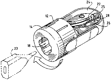
There is described herein a sharpener for a carpenter's pencil having a
centering collar (14) mounted to a base enclosure (12) for relative rotation
to generate the sharpening effect. Within the base enclosure (12) there is a
symmetrical pencil point contour surface (22) and a blade (26;40) mounted
along the contour surface (22) for cutting against the inserted pencil. The
shape of the blade (26;40) is either curved or formed from a plurality of
sections (42,44) to produce a narrow cut around the point extremity of the
pencil and a wider cut further up the pencil shaft.


French Abstract

L'invention concerne un taille-crayon pour crayons de menuisier comportant un collier de centrage (14) monté sur un boîtier de base (12), afin que leur rotation relative produise l'effet aiguisant recherché. Une surface (22) symétrique au contour en forme de pointe de crayon et une lame (26, 40), montée le long de ladite surface, sont montées au sein du boîtier de base (12) afin de tailler le crayon inséré. La forme de la lame (26, 40) est soit recourbée soit composée de plusieurs parties (42, 44), de manière à produire une coupe étroite autour de l'extrémité de la pointe du crayon et une coupe plus large plus haut le long du crayon.

Claims

Note: Claims are shown in the official language in which they were submitted.


1. A pencil sharpening device for cutting a point on the extremity of a flat
pencil
comprising:
a base enclosure having a pencil point contour surface defined therein,
said contour surface having the general shape of a longitudinally concave
cone, being
defined about a central axis and being oriented to present its narrow portion
near the point
extremity of the pencil;
a curved blade mounted within said base enclosure, said blade having a cutting
edge
positioned along said contour surface for cutting against the pencil when the
pencil is rotated
about said central axis; and
centering means for centering the flat pencil along said central axis for
rotation of said
flat pencil about said central axis.
2. The device of Claim 1 wherein said centering means comprises a collar
having a
slot therein for receiving the flat pencil, and wherein said collar is mounted
fox selective rotation
of the pencil and said collar relative to said base enclosure.
3. The device of Claim 2 wherein said base enclosure exhibits an encircling
track
and said collar exhibits an encircling shoulder arranged to fit within said
encircling track of said
base enclosure for enabling said rotation of said collar relative to said base
enclosure.
4. The device of Claim 2 further comprising a plurality of intersecting slots
defined
in said collar for accommodating a plurality of pencil sizes.

5. The device of Claim 1 further comprising an open section defined in said
base
enclosure for allowing the exit of debris.
6. The device of Claim 1 wherein said blade curvature is a single radius curve
with a
radius of approximately 2 1/4 inches.
7. The device of Claim 5 wherein said centering means comprises a collar
having a
slot therein for receiving the flat pencil, and wherein said collar is mounted
for selective rotation
of the pencil and said collar relative to said base enclosure.
8. The device of Claim 7 wherein said base enclosure exhibits an encircling
track
and said collar exhibits an encircling shoulder arranged to fit within said
encircling track of said
base enclosure for enabling said rotation of said collar relative to said base
enclosure.
9. The device of Claim 7 further comprising a plurality of intersecting slots
defined
in said collar for accommodating a plurality of pencil sizes.
10. The device of Claim 9 wherein said collar is selectively removable from
said base
enclosure.
11. The device of Claim 10 wherein said blade is mounted to present said
cutting
edge tangentially to said contour surface.

12. A pencil sharpening device for cutting a point on the extremity of a flat
pencil
comprising:
a base enclosure having a flat pencil point contour surface defined therein,
said contour surface having the general shape of a longitudinally concave
cone, being
defined about a central axis and being oriented to present its narrow portion
near the point
extremity of the flat pencil;
a blade mounted within said base enclosure, said blade exhibiting a plurality
of sections
and having a cutting edge positioned along said contour surface for cutting
against the flat pencil
when the flat pencil is rotated about said central axis; and
centering means for centering the flat pencil along said central axis for
rotation of said
flat pencil about said central axis.
13. The device of Claim 12 wherein said base enclosure exhibits an encircling
track
and said collar exhibits an encircling shoulder arranged to fit within said
encircling track of said
base enclosure for enabling said rotation of said collar relative to said base
enclosure.
14. The device of Claim 13 further comprising a plurality of intersecting
slots defined
in said collar for accommodating a plurality of pencil sizes.
15. The device of Claim 12 wherein said blade is mounted to present said
cutting
edge tangentially to said contour surface.
16. The device of Claim 12 wherein said blade exhibits two straight sections.

17. The device of Claim 12 wherein said centering means comprises a collar
having a
slot therein for receiving the flat pencil, and wherein said collar is mounted
for selective rotation
of the pencil and said collar relative to said base enclosure.
18. The device of Claim 17 wherein said base enclosure exhibits an encircling
track
and said collar exhibits an encircling shoulder arranged to fit within said
encircling track of said
base enclosure for enabling said rotation of said collar relative to said base
enclosure.
19. The device of Claim 18 further comprising a plurality of intersecting
slots defined
in said collar for accommodating a plurality of pencil sizes.
20. The device of Claim 19 wherein said blade exhibits two straight sections.

Description

Note: Descriptions are shown in the official language in which they were submitted.


CA 02338196 2001-O1-19
WO 00/53431 - PCT/US00/06673
PENCIL SHARPENER
Field of the Invention
The present invention relates generally to devices for sharpening pencils
and more particularly to sharpeners designed for the flattened style of
carpenter's
pencils.
Description of the Prior Art
The need for a sharpening device designed for the sharpening of a
carpenter's pencil has long been well known, as sharpening has generally
required
the use of a knife to accommodate the odd shape of the pencil. The difficulty
of
sharpening this style of pencil with such a sharpening device without leaving
wood on the broad sides of the rectangular pencil lead has long presented a
major
obstacle. For example, in U.S. Patent No. 5,077,903 a sharpener is presented
with dual rotary cutter assemblies arranged to cut two curves in the point. In
U.S.
Patents No. 4,759,129 and No. 4,918,816 four cutters and associated gearing
are
similarly used to achieve the desired sharpening effect on a carpenter's
pencil. In
U.S. Patent No. 4,081,010 a cutting blade is driven around the pencil in a
complicated "eccentric" motion by means of cams to achieve the required pencil
point shaping. Clearly, the need for a simplified device that does not require
the
many blades, gears and motors of the prior art has been long sought after, yet
such a device has not previously been developed.

CA 02338196 2001-04-27
SUMMARY OF THE INVENTION
The present invention presents a simplified solution for a device which
will sharpen a carpenter's pencil. Particularly, there is provided a base
enclosure
having a symmetrical pencil point contoured surface defined therein. A blade
mounted within the base enclosure conforms to the contour and cuts against an
inserted pencil. A pencil centering collar is mounted to the base enclosure
for
receiving the pencil and for rotating the pencil relative to the base
enclosure to
cause the sharpening effect on the pencil.
BRIEF DESCRIPTION OF THE DRAWINGS
Figure 1 is a perspective of a sharpening device in accordance with the
present invention, showing a pencil oriented for insertion therein.
Figure 2 is an end view of the collar portion of the sharpening device of
Figure 1, showing the crossed slot feature.
Figure 3 is a side view of the collar of Figure 2.
Figure 4 is a combination cut away and cross section view of the base
enclosure portion of the sharpening device of Figure 1, viewed from the top
with
a portion of the longitudinally concave conical contoured surface and collar
cut
away.
Figure 5 is a cross section view of the base enclosure portion of the
sharpening device of Figure 1, viewed from the side.
Figure 6 is an exploded view of the sharpening device of Figure 1.
2

CA 02338196 2001-O1-19
WO 00/53431. PCT/US00/06673 .
Figure 7 is a cross section view of the base enclosure portion of an
alternate embodiment of the sharpening device employing an alternate version
of
the blade design.
Figure 8 is a perspective view of the alternate blade design of the
sharpening device of Figure 7.
While the invention will be described in connection with a preferred
embodiment, it will be understood that it is not the intent to limit the
invention
to that embodiment. On the contrary, it is the intent to cover all
alternatives,
modifications, and equivalents as may be included within the spirit and scope
of
the invention as defined by the appended claims.
DESCRIPTION OF THE PREFERRED EMBODIMENT
Turning first to Figure 1 there is shown a pencil sharpening device in
accordance with the present invention, having a base enclosure 12 and pencil
centering means, such as a centering collar 14, mounted to the base enclosure
for
rotation relative thereto. The collar 14 exhibits an encircling shoulder 15
(Figure
3) arranged to removably fit within a resilient track 16 encircling the end of
the
base enclosure 12 for allowing rotation of the collar relative to the base
enclosure
12 about a central axis 13 (Figure 6).
The collar further presents an opening 18 for insertion of a pencil to be
sharpened, and in the preferred embodiment the collar opening is in the form
of
3

CA 02338196 2001-04-27
intersecting rectangular slots (Figure 2) designed to accommodate the
dimensions
of a plurality of sizes of carpenter's pencils. For example, a wide pencil can
be
positioned within the wide slot 18a and a narrow pencil can be positioned
within
the narrow slot 18b. Consequently, rotation of the collar with the pencil
inserted
through the collar into the base enclosure causes the pencil to rotate about
the
central axis for the sharpening effect as hereinafter described.
Within the base enclosure there is a pencil point contour surface 22
defined about a central axis 13, the inside shape of a first embodiment of
which
is depicted in Figure 4. This contour matches the desired shape of the
sharpened
end of the pencil; it presents a narrow portion near the point extremity of
the
pencil and a wider portion further up the pencil shaft away from the point
extremity. As shown most clearly in Figures 4 and 5, this contour surface is
of the general shape of a longitudinally concave cone oriented to present its
narrow portion near the point extremity of the pencil.
In the first embodiment (see Figure 5), the edge 22a of the contoured
surface 22 presents a single radius curve in cross section which creates a
curved
cone shape for the desired shape of the sharpened pencil. In this embodiment a
corresponding single radius curve is also employed for the radius of the curie
of
the blade. In the preferred embodiment of this curved version of the
sharpening
device, the radius of the curve is approximately 2 1/4 inches in length.
In a second embodiment (see Figure 7 and Figure 8) the blade 40 is
formed from a plurality of sections, 42 and 44, and the contoured surface
presents, in cross section, an edge 46 having sections corresponding to the
blade
4

CA 02338196 2001-O1-19
WO 00/53431 ~ PCT/IJS00/06673 .
sections. These sections can be straight or curved and additional sections can
be
included to create a more complicated cut if desired. Accordingly, it can be
appreciated that by employing multiple sections, a contoured surface is
created
which is similar to the curved cone shape and matches the desired shape of the
sharpened pencil point; a narrow contour near the pencil point and a wider
contour away from the point.
When the carpenter's pencil is cut to the described contoured shape, a
narrow cut is made around the point while a wider cut is made further up on
the
pencil. Consequently, when the pencil and collar are rotated relative to the
enclosure, wood is sufficiently removed from all sides around the pencil
point,
including the wood from the flat sides 23 (Figure 1) of the pencil shaft, and
a
graduated transition is provided from the vicinity of the pencil point to the
body
of the pencil shaft.
As best shown in Figure 1, the base enclosure is open 24 on one side,
being cut-away to allow for removal of debris cut from the pencil during the
sharpening process. At this open side the contoured surface 22 is interrupted
with
a narrow slot opening 25 where the blade 26 is mounted along the contoured
surface to present a blade edge 28 tangentially to the contoured surface at
the slot
opening.

Representative Drawing
A single figure which represents the drawing illustrating the invention.
Administrative Status

2024-08-01:As part of the Next Generation Patents (NGP) transition, the Canadian Patents Database (CPD) now contains a more detailed Event History, which replicates the Event Log of our new back-office solution.

Please note that "Inactive:" events refers to events no longer in use in our new back-office solution.

For a clearer understanding of the status of the application/patent presented on this page, the site Disclaimer , as well as the definitions for Patent , Event History , Maintenance Fee  and Payment History  should be consulted.

Event History

Description Date
Time Limit for Reversal Expired 2011-03-10
Letter Sent 2010-03-10
Inactive: IPC from MCD 2006-03-12
Grant by Issuance 2003-10-21
Inactive: Cover page published 2003-10-20
Inactive: Final fee received 2003-07-30
Pre-grant 2003-07-30
Notice of Allowance is Issued 2003-03-05
Letter Sent 2003-03-05
Notice of Allowance is Issued 2003-03-05
Inactive: Approved for allowance (AFA) 2003-02-20
Amendment Received - Voluntary Amendment 2003-01-03
Inactive: S.30(2) Rules - Examiner requisition 2002-08-27
Advanced Examination Determined Compliant - paragraph 84(1)(a) of the Patent Rules 2002-08-16
Letter sent 2002-08-16
Inactive: Advanced examination (SO) 2002-07-31
Inactive: Advanced examination (SO) fee processed 2002-07-31
Inactive: Entity size changed 2002-01-02
Letter Sent 2001-10-23
Inactive: Single transfer 2001-08-31
Amendment Received - Voluntary Amendment 2001-04-27
Inactive: Cover page published 2001-04-26
Inactive: First IPC assigned 2001-04-18
Inactive: Courtesy letter - Evidence 2001-04-03
Inactive: Acknowledgment of national entry - RFE 2001-03-30
Application Received - PCT 2001-03-27
All Requirements for Examination Determined Compliant 2001-01-19
Request for Examination Requirements Determined Compliant 2001-01-19
Application Published (Open to Public Inspection) 2000-09-14

Abandonment History

There is no abandonment history.

Maintenance Fee

The last payment was received on 2003-01-22

Note : If the full payment has not been received on or before the date indicated, a further fee may be required which may be one of the following

  • the reinstatement fee;
  • the late payment fee; or
  • additional fee to reverse deemed expiry.

Patent fees are adjusted on the 1st of January every year. The amounts above are the current amounts if received by December 31 of the current year.
Please refer to the CIPO Patent Fees web page to see all current fee amounts.

Owners on Record

Note: Records showing the ownership history in alphabetical order.

Current Owners on Record
PENSHAR, LLC
Past Owners on Record
JOSEPH K. DONALDSON
Past Owners that do not appear in the "Owners on Record" listing will appear in other documentation within the application.
Documents

To view selected files, please enter reCAPTCHA code :


To view images, click a link in the Document Description column. To download the documents, select one or more checkboxes in the first column and then click the "Download Selected in PDF format (Zip Archive)" or the "Download Selected as Single PDF" button.

List of published and non-published patent-specific documents on the CPD .

If you have any difficulty accessing content, you can call the Client Service Centre at 1-866-997-1936 or send them an e-mail at CIPO Client Service Centre.


Document
Description 
Date
(yyyy-mm-dd) 
Number of pages   Size of Image (KB) 
Representative drawing 2001-04-25 1 13
Claims 2003-01-02 4 116
Abstract 2001-01-18 1 58
Description 2001-01-18 5 169
Claims 2001-01-18 5 112
Drawings 2001-01-18 4 84
Description 2001-04-26 5 171
Claims 2001-04-26 5 109
Notice of National Entry 2001-03-29 1 202
Reminder of maintenance fee due 2001-11-13 1 112
Courtesy - Certificate of registration (related document(s)) 2001-10-22 1 113
Commissioner's Notice - Application Found Allowable 2003-03-04 1 160
Maintenance Fee Notice 2010-04-20 1 170
Correspondence 2001-03-29 1 24
PCT 2001-01-18 2 58
Correspondence 2003-07-29 1 33