Note: Descriptions are shown in the official language in which they were submitted.
CA 02338575 2003-10-22
CLUTCH AND DRIVE DEVICE HAVING THE CLUTCH
TECHNICAL FIELD
The present invention relates to a clutch comprising a
driving rotor and a driven rotor, and more particularly, to a
clutch for blocking the transmission of rotation from a
driven rotor to a driving rotor and a driving apparatus
equipped with the clutch.
BACKGROUND
A general power window apparatus comprises a driving
apparatus serving as a driving source, and a driven device
driven by the driving apparatus which moves a windowpane up
and down, specifically, a lifting mechanism. The driving
apparatus includes an output unit equipped with a gear
mechanism. The rotation of the motor is transmitted to the
lifting mechana~ism through the gear mechanism. The lifting
mechanism converts the rotation of the motor to up/down
movements of the windowpane.
When external force is applied to the windowpane while
the motor is not driven, the external force is transmitted
from the windowpane to the motor through the lifting
mechanism and the gear mechanism. 'Therefore, when external
force is applied to the windowpane, the windowpane is allowed
to move. Further, the gear constituting the gear mechanism
may be damaged.
To prevent the movement of the windowpane caused by
external force, the driving apparatus is equipped with a
clutch. The clutch is located in the middle of a power
1
CA 02338575 2001-01-26
transmission path between the motor and the lifting mechanism
in the output unit. The clutch allows the power of the motor
to be transmitted to the lifting mechanism through the output
unit. However, when external force is applied to the
windowpane, the clutch is locked to make a rotation
impossible in order to prevent the external force from moving
the lifting mechanism. In other words, the clutch blocks the
transmission of movement from the lift mechanism to the
motor.
Japanese Unexamined Patent Publication No. Hei 7-103260
discloses a clutch of this type. As illustrated in Figure
52, the clutch 750 comprises a cylindrical clutch housing
751, a driving rotor 762, a driven rotor 753, and a plurality
of rolling bodies 754. The driving rotor 762 is rotated by a
driving source (not shown) such as a motor. The driving
rotor 762 has a plurality of engagement bodies 752 arranged
at equal angular intervals which are rotatably accommodated
in a clutch housing 751. The driven rotor 753 is
accommodated in the clutch housing 751 such that it is
surrounded by the engagement bodies 752. The driven rotor
753 is provided with a plurality of restriction faces 753a on
its outer peripheral face. The rolling bodies 754 are
located between the restriction faces 753a and the inner
peripheral face of the clutch housing 751 such that they are
positioned between respective two adjacent engagement bodies
752.
As the driving rotor 762 is rotated by the driving
source, ends 752a of the engagement bodies 752 are engaged
with the corresponding rolling bodies 754. With further
rotation of the driving rotor 762, the rolling bodies 754 are
held between the engagement bodies 752 and the restriction
faces 753a of the driven rotor 753 to couple the driven rotor
753 to the driving rotor 762 for rotation integral therewith.
2
CA 02338575 2001-01-26
Thus, the rotation of the driving rotor 762 is transmitted to
the driven rotor 753 through the rolling bodies 754, causing
the driven rotor 753 to rotate together with the driving
rotor 762 in the clutch housing 751. With the rotation of
the driven rotor 753, a driven device (not shown) coupled to
the driven rotor 753 is driven.
On the other hand, as the driven rotor 753 is rotated by
a movement of the driven device resulting from external force
or the like, the restriction faces 753a moves the rolling
bodies 754 toward the inner peripheral face of the clutch
housing 751 through the respective two adjacent engagement
bodies 752. With further rotation of the driven rotor 753,
the rolling bodies 754 are held between the restriction faces
753a and the inner peripheral face of the clutch housing 751
to lock the driven rotor 753 to the clutch housing 751 to
prevent the rotation thereof. Thus, the transmission of
rotation from the driven rotor 753 to the driving rotor 762
is blocked, together with the movement of the driven device
being blocked.
In the foregoing clutch 750, when the rolling bodies 754
are held between the restriction faces 753a and the
engagement bodies 752 by the rotation of the driving rotor
762, the rolling bodies 754 may not be released from the held
state when the driven rotor 753 is rotated subsequently by a
movement of the driven device. In such a case, the driven
rotor 753 is not locked in a manner disabling the rotation,
thereby allowing the rotation of the driven rotor 753 to be
transmitted to the driving rotor 762 through the rolling
bodies 754, thereby failing to block the movement of the
driven device.
Japanese Unexamined Patent Publication No. Hei 8-200401,
on the other hand, discloses a clutch for transmitting the
3
CA 02338575 2001-01-26
rotation of a driving rotor to a driven rotor through a knock
pin (switch pin). However, the knock pin is in contact with
a member engaged with the knock pin with a small area. -For
this reason, during the transmission of rotation, force
intensively acts between the knock pin and the member engaged
with the knock pin. For making the clutch durable to such
intensive force, the clutch must be formed with a high
strength. This increases a manufacturing cost of the clutch.
SUMMARY OF THE INVENTION
It is an object of the present invention to provide a
clutch that is capable of reliably blocking the transmission
of rotation from a driven rotor to a driving rotor and of
reducing a required strength, and a driving apparatus
equipped with the clutch.
To achieve the above object, a clutch according to the
present invention comprises a driving rotor coupled to a
driving source,/a driven rotor directly engaged with the
driving rotor such that the driven rotor is driven by the
driving rotor, a housing for accommodating the driving rotor
and the driven rotor, and a lock member located between the
driven rotor and the housing. The lock member is circulated
about an axial center of the driving rotor associated with
rotation of the driving rotor. The lock member is held
between the driven rotor and the housing to block rotation of
the driven rotor relative to the housing when the driven
rotor itself is rotated. The lock member is released from
the held state to allow the driving rotor to rotate the
driven rotor relative to the housing when the driving source
rotates the driving rotor.
The rotation of the driven rotor itself relative to the
4
CA 02338575 2001-01-26
housing is blocked by the lock member which is held between
the driven rotor and the housing. When the driving source
rotates the driving rotor, the lock member is released from
the held state. This allows the transmission of the rotation
from the driving rotor to the driven rotor without fail and
blocks the transmission of the rotation from the driven rotor
to the driving rotor without fail, as compared with a clutch
in which a lock member is brought into a held state whenever
the driving rotor is rotated or the driven rotor is rotated.
Further, since the driven rotor is directly engaged with the
driving rotor, a large contact area can be ensured between
both rotors. For this reason, the strength required for both
rotors can be reduced.
The present invention also provides a driving apparatus
comprising a clutch constructed as described above. The
driving apparatus comprises a motor having a rotating shaft
and functioning as a driving source, and an output unit
coupled to the motor. The output unit comprises a
decelerating mechanism for decelerating the rotation of the
rotating shaft before transmission to a driven device. The
clutch is located between the rotating shaft and the
decelerating mechanism.
The clutch located between the rotating shaft and the
decelerating mechanism is not subjected to a large load.
Therefore, the durability required for the clutch can be
reduced with a result of a smaller-size clutch.
In another aspect of the driving apparatus according to
the present invention, the clutch is located between the
decelerating mechanism and the driven device in the output
unit. In this way, a movement of the driven device based on
force applied to the driven device can be satisfactorily
blocked in a stage near the driven device.
5
CA 02338575 2001-01-26
BRIEF DESCRIPTION OF THE DRAWINGS
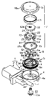
Figure 1 is an exploded perspective view illustrating a
driving apparatus equipped with a clutch according to a first
embodiment of the present invention;
Figure 2 is a perspective view illustrating a driving
rotor located in the clutch in Figure 1;
Figure 3 is a perspective view illustrating a driven
rotor located in the clutch in Figure 1;
Figure 4 is a plane cross-sectional view of the clutch
in Figure 1, and more specifically, a cross-sectional view
taken along the line 4-4 in Figure 5;
Figure 5 is a cross-sectional view taken along the 5-5
line in Figure 4;
Figures 6(a) and 6(b) are partial cross-sectional views
for explaining the operation of the clutch in Figure 1;
Figures 7(a) and 7(b) are partial cross-sectional views
for explaining the operation of the clutch in Figure 1;
Figure 8 is a general structural view of a power window
apparatus equipped with the driving apparatus of Figure 1;
Figure 9i/s an exploded perspective view of a clutch
according to a second embodiment of the present invention;
Figure 10 is a plane cross-sectional view of the clutch
of Figure 9, and more specifically, a cross-sectional view
taken along the line 10-10 in Figure 11;
Figure 11 is a cross-sectional view taken along the 11-
11 line in Figure 10;
Figures 12(a) and 12(b) are partial cross-sectional
views for explaining the operation of the clutch of Figure 9;
Figures 13(a) and 13(b) are partial cross-sectional
views for explaining the operation of the clutch of Figure 9;
Figure 14 is a plane cross-sectional view illustrating a
clutch according to a third embodiment of the present
invention;
Figure 15 is a partial plane cross-sectional view
6
CA 02338575 2001-01-26
illustrating a clutch according to a fourth embodiment of the
present invention;
Figures 16(a) through 16(c) are partial front sectional
views illustrating a clutch according to a fifth embodiment
of the present invention;
Figure 17 is an exploded perspective view illustrating a
driving apparatus equipped with a clutch according to a sixth
embodiment of the present invention;
Figure 18 is a plane cross-sectional view of the driving
apparatus of Figure 15;
Figure 19 is an exploded perspective view of a clutch
located in the driving apparatus of Figure 15;
Figure 20 is a plane cross-sectional view of the clutch
of Figure 19;
Figures 21(a) and 21(b) are partial cross-sectional
views for explaining the operation of the clutch of Figure
19;
Figures 22(a) and 22(b) are partial cross-sectional
views for explaining the operation of the clutch of Figure
19;
Figure 23 /is a perspective view illustrating a support
ring located in a clutch according to a seventh embodiment of
the present invention;
Figure 24 is a front cross-sectional view illustrating a
clutch comprising the support ring of Figure 23;
Figure 25 is a plane cross-sectional view illustrating a
clutch according to an eighth embodiment of the present
invention;
Figure 26(a) is a plane cross-sectional view
illustrating a clutch according to a ninth embodiment of the
present invention, and more specifically, a cross-sectional
view taken along the line 26(a)-26(a) in Figure 26(b);
Figure 26(b) is a cross-sectional view taken along the
line 26(b)-26(b) in Figure 26(a);
Figure 27 is an exploded perspective view illustrating a
7
CA 02338575 2001-01-26
driving apparatus equipped with a clutch according to a tenth
embodiment of the present invention;
Figure 28 is a plane cross-sectional view of the driving
apparatus of Figure 27;
Figure 29 is a cross-sectional view taken along the line
29-29 in Figure 28;
Figure 30 is an exploded perspective view illustrating
the clutch located in the driving apparatus of Figure 27;
Figure 31 is a plane cross-sectional view of the clutch
of Figure 30;
Figure 32 is a partial cross-sectional view illustrating
a portion of the clutch in the driving apparatus of Figure 28
in an enlarged view;
Figures 33(a) and 33(b) are partial cross-sectional
views for explaining the operation of the clutch of Figure
30;
Figures 34(a) and 34(b) are partial cross-sectional
views for explaining the operation of the clutch of Figure
30;
Figures 35(a) and 35(b) are partial cross-sectional
views for expli.ning the operation of the clutch of Figure
30;
Figures 36(a) and 36(b) are partial cross-sectional
views for explaining the operation of the clutch of Figure
30;
Figure 37 is a partial perspective view illustrating a
structure for coupling an output unit to a clutch in the
driving apparatus of Figure 27;
Figure 38 is a plane cross-sectional view illustrating a
clutch according to an eleventh embodiment of the present
invention;
Figure 39 is a plane cross-sectional view illustrating a
clutch according to a twelfth embodiment of the present
invefttion;
Figure 40 is an exploded perspective view illustrating a
8
CA 02338575 2001-01-26
clutch according to a thirteenth embodiment of the present
invention;
Figure 41 is a cross-sectional view of the clutch of
Figure 40;
Figure 42 is a partially cutaway perspective view
illustrating a support member located in the clutch of Figure
40;
Figures 43(a) and 43(b) are partial cross-sectional view
for explaining the operation of the clutch of Figure 40;
Figure 44 is a cross-sectional view illustrating a
clutch according to a fourteenth embodiment of the present
invention;
Figure 45 is a cross-sectional view illustrating a
clutch according to a fifteenth embodiment of the present
invention;
Figure 46 is a cross-sectional view illustrating a
clutch according to a sixteenth embodiment of the present
invention;
Figure 47 is a cross-sectional view illustrating a
clutch according to a seventeenth embodiment of the present
invention;
Figure 48is a cross-sectional view illustrating a
clutch according to an eighteenth embodiment of the present
invention;
Figure 49 is an exploded perspective view illustrating a
clutch according to a nineteenth embodiment of the present
invention;
Figure 50 is a cross-sectional view of the clutch of
Figure 49;
Figures 51(a) and 51(b) are partial cross-sectional
views for explaining the operation of the clutch of Figure
49; and
Figure 52 is a plane cross-sectional view illustrating
the clutch of prior art.
9
CA 02338575 2003-10-22
DETAILED DESCRIPTION OF THE PREFERRED EMBODIMENTS
First Embodiment
In the following, a first embodiment which embodies the
present invention in a power window apparatus will be
described with reference to Figures 1 through 8.
As illustrated in Figure 8, the power window apparatus
is located within a door 260 of a vehicle for moving a
windowpane 250 up and down. The power window apparatus
comprises a driving apparatus 1 fixed to the inside of the
door 260, and a lifting mechanism 270 driven by the driving
apparatus 1 for moving the windowpane 250 up and down. The
driving apparatus 1 includes a motor 2 and an output unit 3.
The output unit 3 has an output shaft 10 formed with a gear
10a. The rotation of the motor 2, which is decelerated by
the output unit 3, istransmitted to the output shaft 10.
The lifting mechanism 270 as a driven device includes two
arms which intersect each other, wherein both arms are
interlocked by a shaft in the middle. Upper ends of both
arms are coupled to the windowpane 250. One of the arms has
a fan-shaped gear 270a, at a lower end thereof, meshed with
the gear l0a of the output shaft 10. As the motor 2 is
driven to rotate the gear 10a, the lifting mechanism 270
moves the windowpane 250 up and down.
As illustrated in Figures 1 and 5, the driving apparatus
1 has the output unit 3 coupled to'the motor 2. The output
unit 3 comprises a unit housing 4, a worm shaft 100 (see
Figure 5), a worm wheel 5, a buffer member 6, a clutch 7, and
an output shaft 10. The worm shaft 100 and the worm wheel 5
comprise a worm gear mechanism which functions as a
decelerating mechanism and a torque amplifying mechanism.
The unit housing 4 comprises a worm accommodating
CA 02338575 2001-01-26
portion 4d in the form of closed cylinder for accommodating
the worm shaft 100. The worm shaft 100 illustrated in Figure
is formed integrally with the rotating shaft of the motor
2, and extends from the motor into the worm accommodating
5 portion 4d.
As illustrated in Figures 1 and 5, the unit housing 4
comprises a wheel accommodating portion 4a for accommodating
the worm wheel S. The wheel accommodating portion 4a
generally has a closed cylindrical shape, with a support
cylinder 4b being implanted on its inner bottom. The support
cylinder 4b has a shaft hole 4c for rotatably supporting the
output shaft 10.
The worm wheel 5, which is made of a resin material,
includes a gear wheel 5a having a cylindrical body and an
annular bottom plate, and a central cylindrical body 5b
extending from the bottom plate of the gear wheel 5a. The
support cylinder 4b is fitted into the shaft hole 5c of the
cylindrical body 5b to rotatably support the worm wheel 5 by
the support cyliinder 4b in the wheel accommodating portion
4a. In this event, the gear wheel 5a is meshed with spiral
teeth 100d of the worm shaft 100.
Three holding walls 5d arranged at equal angular
intervals (120 ) extend in radial directions from the inner
peripheral face of the gear wheel 5a to the cylindrical body
5b. A holding chamber X is formed between two adjacent
holding walls 5d. Further, a coupling groove Y for coupling
two adjacent holding chambers X is formed between each
holding wall 5d and the outer peripheral face of the
cylindrical body 5b.
The buffer member 6, which is made of rubber, is located
in the worm wheel 5. The buffer member 6 includes three fan-
11
CA 02338575 2001-01-26
shaped rubber segments 6a arranged at equal angular intervals
(120 ), and elongated coupling rubbers 6b for coupling two
adjacent rubber segments 6a to each other, and generally has
an annular shape. The rubber segments 6a are located in the
respective holding chambers X, and the coupling rubbers 6b
are located in the respective coupling grooves Y. Therefore,
the buffer member 6 is mounted to the worm wheel 5 for
rotation integral therewith. Each rubber segment 6a has a
radially extending slit 6c at an intermediate location in the
circumferential direction.
As illustrated in Figure 1, the clutch 7 comprises a
driving rotor 11, a driven rotor 12, an outer ring 13 as a
housing, a plurality (three in this embodiment) of rollers
14, a washer 15 as a restriction plate, and a cap 16 as a
restriction plate.
As illustrated in Figures 1 and 2, the driving rotor 11
is formed of a resin material in a generally disc shape. The
driving rotor 11 has three stopper pieces 21 arranged at
equal angular imtervals. As illustrated in Figure 5, when
the driving rotor 11 is mounted on the worm wheel 5, these
stopper pieces 21 are engaged with the slits 6c of the buffer
member 6, respectively. Therefore, the rotation of the worm
wheel 5 is transmitted to the driving rotor 11 through the
buffer member 6, causing the driving rotor 11 to rotate
integrally with the worm wheel 5.
As illustrated in Figures 1, 2 and 4, the driving rotor
11 has a shaft hole lla, at the center thereof, which allows
the output shaft 10 to insert therethrough. The driving
rotor 11 has a first engagement hole 22 and a second
engagement hole 24, which extend in the circumferential
direction, between two adjacent stopper pieces 21. The first
engagement hole 22 is open to the outer peripheral side of
12
CA 02338575 2001-01-26
the driving rotor 11 through a notch 23. The notch 23 is
positioned at an intermediate location in the circumferential
direction of the first engagement hole 22. Assuming that the
diameter of the driving rotor 11 is Rl; the outer diameter of
both the engagement holes 22, 24 is R2; and the inner
diameter of both the engagement holes 22, 24 is R3, the width
W1 of the notch 23 in the radial direction is represented by
Rl-R2. 10 Each notch 23 is defined by a first surface 23a and a
second surface 23b which oppose each other in the
circumferential direction and function as pressing faces.
The distance between the first surface 23a and the second
surface 23b in the circumferential direction is larger than
the width W1.
The first engagement hole 22 is defined on both
circumferential sides thereof by a first engagement face 22a
and a second engagement face 22b as driving engagement faces.
The second engagement hole 24 is defined on both
circumferentialisides thereof by a first engagement face 24a
and a second engagement face 24b as driving engagement faces.
As illustrated in Figures 1 and 3, the driven rotor 12
is formed of a metal material in a generally disc shape, and
overlapped on the driving rotor 11. The driven rotor 12 has
a diameter equal to the outer diameter R2 of both engagement
holes 22, 24. The driven rotor 12 has a fitting hole 12a of
a cross shape in cross section at the center thereof. An end
of the output shaft 10 is fitted into the fitting hole 12a.
Thus, the driven rotor 12 is integrally rotatable with the
output shaft 10.
The driven rotor 12 has a plurality of engagement bodies
41 which extend in radial directions and protrude in the
13
CA 02338575 2001-01-26
axial direction. In Figure 3, three first engagement bodies
41 are arranged at equal angular intervals. As illustrated
in Figure 4, each of the first engagement bodies 41 is
accommodated in the first engagement hole 22 of the driving
rotor 11. Each of the first engagement bodies 41 has a
circumferential width smaller than the circumferential width
of the first engagement hole 22 and larger than the
circumferential width of the notch 23. Thus, the first
engagement bodies 41 are movable in the first engagement hole
22 within the circumferential length of the first engagement
hole 22.
The first engagement body 41 has, on both
circumferential sides thereof, a first side face 41a opposite
to the first engagement face 22a of the first engagement hole
22 and a second side face 41b opposite to the second
engagement face 22b of the first engagement hole 22. The
first side face 41a and the second side face 41b function as
driven engagement faces. As illustrated in Figure 6(a), as
the driving rotor 11 rotates in the clockwise direction, the
first engagemer~t face 22a comes in contact with the first
surface 41a and presses the same. Therefore, the driven
rotor 12 integrally rotates in the clockwise direction
together with the driving rotor 11. As illustrated in Figure
6(b), as the driving rotor 11 rotates in the counterclockwise
direction, the second engagement face 22b comes in contact
with the second side face 41b and presses the same.
Therefore, the driven rotor 12 integrally rotates in the
counterclockwise direction together with the driving rotor
11.
As illustrated in Figures 3 and 4, each of the first
engagement bodies 41 has a shallow V-shaped groove on its
outer peripheral face at an intermediate location in the
circumferential direction. The V-shaped groove is defined by
14
CA 02338575 2001-01-26
a V-shaped restriction face 41c formed on the outer
peripheral face of the first engagement body 41. The
distance R5 from the center of the driven rotor 12 to the
intermediate location of the restriction face 41c in the
circumferential direction, i.e., to the bottom center of the
V-shaped groove is smaller than the radius of a portion of
the driven engagement body 41 except for the restriction face
41c.
The driven rotor 12 has a plurality of second engagement
bodies 42 which extend in radial directions and protrude in
the axial direction between two adjacent first engagement
bodies 41. In Figure 3, three second engagement bodies 42
are arranged at equal angular intervals. As illustrated in
Figure 4, each of the second engagement bodies 42 is
accommodated in the second engagement hole 24 of the driving
rotor 11. Each of the second engagement bodies 42 has a
circumferential width smaller than the circumferential width
of the second engagement hole 24. Thus, the second
engagement bodies 42 are movable in the second engagement
hole 24 within i ithe circumferential length of the second
engagement hole 24.
The second engagement body 42 has, on both
circumferential sides thereof, a first side face 42a opposite
to the first engagement face 24a of the second engagement
hole 24 and a second side face 42b opposite to the second
engagement face 24b of the second engagement hole 24. The
first side face 42a and the second side face 42b function as
driven engagement faces. As illustrated in Figure 6(a),
simultaneously with the first engagement face 22a coming in
contact with the first side face 41a, the first engagement
face 24a comes in contact with the first side face 42a. As
illustrated in Figure 6(b), simultaneously with the second
engagement face 22b coming in contact with the second side
CA 02338575 2001-01-26
face 41b, the second engagement face 24b comes in contact
with the second side surface 42b.
The driving rotor 11 and the driven rotor 12 are
rotatably accommodated in the outer ring 13. The outer ring
13 is formed in an annular shape, and is fixed to the unit
housing 4 through the cap 16 as illustrated in Figure 5. As
illustrated in Figure 4, the rollers 14 as rolling bodies are
located between the restriction faces 41c and the inner
peripheral face of the outer ring 13 within the notch 23 of
the driving rotor 11. The rollers 14 extend in parallel with
the axis of the driving rotor 11. The roller 14 has a
diameter D larger than the radial width W1 of the notch 23.
As illustrated in Figure 6(a), as the driving rotor 11
rotates in the clockwise direction, the first engagement face
22a comes in contact with the first side face 41a, and the
first surface 23a of the notch 23 comes in contact with the
roller 14. In this event, the axial center of the roller 14
is positioned on a radial line which passes the axial center
of the driven r,otor 12 and an intermediate location of the
restriction face 41c in the circumferential direction.
Conversely, as illustrated in Figure 6(b), as the driving
rotor 11 rotates in the counterclockwise direction, the
second engagement face 22b comes in contact with the second
side surface 41b, and the second surface 23b of the notch 23
comes in contact with the roller 14. In this event, the
axial center of the roller 14 is also positioned on the
radial line which passes the axial center of the driven rotor
12 and the intermediate location of the restriction face 41c
in the circumferential direction.
As illustrated in Figures 4, 6(a) and 6(b), when the
roller 14 is placed at a position corresponding to the
intermediate location of the restriction face 41c in the
16
CA 02338575 2001-01-26
circumferential direction, the roller 14 is placed between
the restriction face 41c and the inner peripheral face of the
outer ring 13 with a clearance. Stated another way, the
roller 14 is not held between the restridtion face 35c and
the inner peripheral face of the outer ring 13. In the
following, such a state is referred to as the "free state" of
the roller 14. When the roller 14 is in the free state, the
driven rotor 12 is allowed to rotate relative to the outer
ring 13.
Thus, as illustrated in Figures 6(a) and 6(b), when the
driving rotor 11 rotates in the clockwise direction or in the
counterclockwise direction, the roller 14 is brought into the
free state, so that the driven rotor 12 can rotate relative
to the outer ring 13 together with the driving rotor 11. The
roller 14 circulates about the axial center of the driving
rotor 11 as it is pressed by the first surface 23a or second
surface 23b of the notch 23, and maintained in the free
state.
On the otITer hand, as illustrated in Figure 7(a), as the
driven rotor 12 itself rotates in the counterclockwise
direction, the restriction face 41c of the first engagement
body 41 moves relative to the roller 14 such that the roller
14 is held between the restriction face 41c and the inner
peripheral face of the outer ring 13. As illustrated in
Figure 7(b), when the driven rotor 12 itself rotates in the
clockwise direction, the restriction face 41c of the first
engagement body 41 moves relative to the roller 14 as well,
such that the roller 14 is held between the restriction face
41c and the inner peripheral face of the outer ring 13. In
the following, the state in which the roller 14 is held
between the restriction face 41c and the inner peripheral
face of the outer ring 13 is referred to as the "lock state"
of the roller 14. When the roller 14 is in the lock state,
17
CA 02338575 2001-01-26
the driven rotor 12 is prevented from rotating relative to
the outer ring 13. The roller 14 functions as a lock member.
As illustrated in Figures 1 and 5, the washer 15 is
formed of a metal material, preferably of brass, in an
annular shape. The washer 15 is fixed to the cap 16 and
positioned to surround the stopper pieces 21 of the driving
rotor 11. As illustrated in Figure 5, the washer 15 has a
spring 15a, at its inner peripheral location, as urging means
which is in contact with a lower surface of the roller 14.
The spring 15a urges the roller 14 upward in Figure 5, in
other words, axially toward the inner surface of the cap 16.
The washer 15 and the cap 16 comprise restricting means for
restricting axial movements of the roller 14.
The cap 16, which is formed of a metal material
substantially in a closed cylinder, is mounted on the unit
housing 4 to close an opening of the wheel accommodating
portion 4a. The washer 15 is fitted into the cap 16 in a
manner disabling the rotation. The cap 16 is formed at an
outer periphera/l location with a fitting portion 16a which
fits into the wheel accommodating portion 4a.
As illustrated in Figure 5, the output shaft 10 is
inserted into the support cylinder 4b of the wheel
accommodating portion 4a from the bottom of the unit housing
4, and inserted through the shaft hole lla of the driving
rotor 11, with its upper end protruding upward from the shaft
hole lla. The upper end of the output shaft 10 is fitted
into the fitting hole 12a of the driven rotor 12. The output
shaft 10 is formed with a hole in the upper end surface, into
which a positioning boss formed on the cap 16 is fitted. On
the other hand, a portion of the output shaft 10, which
protrudes outward from the unit housing 4, is provided with a
gear, as mentioned above. The gear l0a is meshed with a fan-
18
CA 02338575 2001-01-26
shaped gear 270a of a lifting mechanism 270 (see Figure 8).
Next, the operation of the power window apparatus
constructed as described above will be described.
As the motor 2 is started, the worm shaft 100 rotates
the worm wheel 5. The rotation of the worm wheel 5 is
transmitted to the driving rotor 11 of the clutch 7 through
the buffer member 6. The driving rotor 11 causes the driven
rotor 12 to rotate together therewith. In this event, as
described with reference to Figures 6(a) and 6(b), the
rollers 14 are maintained in a free state, the driven rotor
12 is allowed to rotate relative to the outer ring 13. The
rotation of the driven rotor 12 is transmitted to the output
shaft 10. The rotation of the output shaft 10 drives the
lifting mechanism 270 to open or close the windowpane 250.
On the other hand, when external force is applied to the
windowpane 250 while the motor 2 is being stopped, the
external force is transmitted to the output shaft 10 through
the lifting mecrhanism 270 to rotate the output shaft 10. The
rotation of the output shaft 10 is transmitted to the driven
rotor 12. In this event, as previously explained with
reference to Figures 7(a) and 7(b), the roller 14 is held
between the restriction face 41c of the first engagement body
41 and the inner peripheral face of the outer ring 13, and
thus brought into the lock state. When the roller 14 is in
the lock state, the rotation of the driven rotor 12 relative
to the outer ring 13 is blocked. The outer ring 13 is
mounted to the unit housing in a manner disabling the
rotation. This results in blocking movements of the output
shaft 10, the lifting mechanism 270 and the windowpane 250.
It is therefore impossible to open or close the windowpane
250 with the external force. Of course, neither the driving
rotor 11 nor the worm wheel 5 and the worm shaft 100 coupled
19
CA 02338575 2001-01-26
thereto rotates.
In this way, while the clutch 7 allows the transmission
of the movement from the motor 2 to the lift mechanism 270
(driven device), it prevents movements of the output unit 3
based on force applied to the lifting mechanism 270 to block
the transmission of the movement from the lift mechanism 270
to the motor 2.
This embodiment has advantages shown below.
Since the rollers 14 are maintained in the free state
when the driving rotor 11 is rotated by the motor 2, the
driven rotor 12 can integrally rotate together with the
driving rotor 11. Thus, the windowpane 250 can be opened or
closed as the motor 2 is driven.
When the driven rotor 12 is rotated based on force
applied to the windowpane 250, the rollers 14 are brought
into a lock state to block the rotation of the driven rotor
12, thereby ensuring to block the transmission of the
rotation of the driven rotor 12 to the driving rotor 11.
Each of the plurality of rollers 14 is brought into the
lock state to block the rotation of the driven rotor 12
whether the driven rotor 12 is rotated in the forward or
backward direction. In other words, each of the rollers 14
functions to block not only the rotation of the driven rotor
12 in one direction but also the rotation in both directions.
Therefore, as compared with a clutch which comprises rollers
for blocking a driven rotor from rotating in one direction
and rollers for blocking the driven rotor from rotating in
the other direction, the number of rollers 14 can be reduced,
resulting in a reduction in the number of parts. This
permits a simplified structure of the clutch 7 and a
CA 02338575 2001-01-26
reduction in the size and cost of the clutch 7.
When the driving rotor 11 rotates from the lock state of
the rollers illustrated in Figures 7(a) and 7(b), the rollers
14 simply and reliably transit to the free state by the
driving rotor 11 which directly presses the rollers 14, or by
a movement of the driven rotor 12 associated with the
rotation of the driving rotor 11. In this way, the rotation
of the driving rotor 11 is transmitted to the driven rotor 12
without fail.
The engagement faces 22a or 22b of the three first
engagement holes 22 are in contact with the three first
engagement bodies 41 corresponding thereto over the entire
surfaces thereof, and the engagement faces 24a or 24b of the
three second engagement holes 24 are in contact with the
three engagement bodies corresponding thereto over the entire
surfaces, thereby transmitting the driving power from the
driving rotor 11 to the driven rotor 12. Stated another way,
since the driving rotor 11 is in contact with the driven
rotor 12 with a relatively wide area to transmit the driving
power, force applied to both the rotors 11, 12 per unit area
is relatively small. This improves the durability of the
driving rotor 11 and the driven rotor 12 as compared with the
clutch which transmits the power through a knock pin as in
Japanese Unexamined Patent Publication No. Hei 8-200401
previously described in Background Art. In other words, the
strength required for the driving rotor 11 and the driven
rotor 12 can be reduced. Thus, the driving rotor 11, in
particular, can be molded of a synthetic resin which is light
in weight, inexpensive, and easy to manufacture.
The rollers 14 of the clutch 7 are in the lock state
only when force is transmitted from the lifting mechanism 270
to the driven rotor 12. The rollers 14 are in the free state
21
CA 02338575 2001-01-26
when the power is transmitted from the motor 2 to the driving
rotor 11. Supposing the employment of a clutch which is
constructed such that the rollers are brought into the lock
state even when the power is transmitted from the motor to
the driving rotor, the rollers and the members for locking
the rollers tend to be charged with a burden. In this
respect, the clutch 7 of this embodiment, in which the
rollers 14 are brought into the lock state only when the
power is transmitted from the lifting mechanism 270 to the
driven rotor 12, is superior in durability. Moreover, it is
ensured to transmit the rotation of the driving rotor 11 to
the driven rotor 12, and to block the rotation of the driven
rotor 12 from being transmitted to the driving rotor 11.
The rollers 14 formed in a cylindrical shape, is in
linear contact with the inner peripheral face of the outer
ring 13 and the restriction faces 41c of the first engagement
body 41 in its lock state. Therefore, in comparison with the
case where a ball is used in place of the cylindrical roller
14, for example, the lock state can be more reliably
provided. / /
The washer 15 has a spring 15a for urging the roller 14
toward the inner surface of the cap 16. As a result, the
roller 14 is stabilized in posture and movement, so that the
roller 14 can smoothly transit from the free state to the
lock state and vice versa.
The clutch 7 is positioned on the side near the lifting
mechanism 270 in the output unit 3. Therefore, a movement of
the lifting mechanism 270 caused by force applied to the
windowpane 250 can be satisfactorily blocked in a stage near
the lifting mechanism 270.
Second Embodiment
22
CA 02338575 2001-01-26
Next, a clutch according to a second embodiment of the
present invention will be described with reference to Figures
9 through 13. Figure 9 illustrates an exploded perspective
view of a clutch 50 in this embodiment. The clutch 50 is
also located in a driving apparatus for a power window
apparatus, in a manner similar to the clutch 7 illustrated in
Figure 1. The clutch 50 comprises a clutch housing 51, a
driving rotor 52, a driven rotor 53, a plurality (three in
this embodiment) of rollers 54, and a washer 55.
The driving rotor 52, which is made of a resin material,
comprises a coupling shaft 52a and a disk 52b. Though not
particularly illustrated, the coupling shaft 52a is coupled
to a rotating shaft of a motor through a gear mechanism or
the like, in a manner similar to the embodiment illustrated
in Figure 1. As illustrated in Figure 11, an annular
protrusion 52c is formed on the base of the disk 52b,
arranged coaxially with the coupling shaft 52a. The disk 52b
corresponds to the driving rotor 11 illustrated in Figure 2
from which the stopper pieces 21 are removed and in which the
annular protrusion 52c is provided for the driving rotor 11.
More specifically, as illustrated in Figures 9 and 10,
the disk 52b has first engagement holes 61, second engagement
holes 63, and a notch 62 corresponding to the first
engagement holes 22, the second engagement holes 24, and a
notch 23 of the driving rotor 11 illustrated in Figure 2.
Each of the first engagement holes 61 are defined on both its
circumferential sides by a first engagement face 61a and a
second engagement face 61b as driving engagement faces. Each
of the second engagement holes 63 is defined on both
circumferential sides thereof by a first engagement face 63a
and a second engagement face 63b as driving engagement faces.
Each notch 62 is defined by a first surface 62a and a second
surface 62b which oppose each other in the circumferential
23
CA 02338575 2001-01-26
direction and function as pressing faces.
The driven rotor 53, which is made of a metal material,
comprises a coupling shaft 53a and a disk 53b. Though not
particularly illustrated, the coupling shaft 53a is coupled
to the output shaft, in a manner similar to the embodiment
illustrated in Figure 1. The disk 53b has an annular groove
53c for engagement with the annular protrusion 52c of the
driving rotor 52. The disk 53b corresponds to the driven
rotor 12 illustrated in Figure 3 from which the fitting hole
12a is removed and in which the annular groove 53c is
provided.
More specifically, as illustrated in Figures 9 and 10,
the disk 53b has first engagement bodies 71 and second
engagement bodies 72 corresponding to the first engagement
bodies 41 and the second engagement bodies 42 of the driven
rotor 12 illustrated in Figure 3. Each of the first
engagement bodies 71 has, on both circumferential sides
thereof, a first side face 71a opposite to the first
engagement face 61a of the first engagement hole 61 and a
second side face 71b opposite to the second engagement face
61b of the first engagement hole 61. Each of the first
engagement bodies 71 also has a V-shaped restriction face 71c
at an intermediate location of its outer peripheral face in
the circumferential direction. Each of the second engagement
bodies 72 has, on both circumferential sides thereof, a first
side face 72a opposite to the first engagement face 63a of
the second engagement hole 63 and a second side face 72b
opposite to the second engagement face 63b of the second
engagement hole 63.
The driving rotor 52 and the driven rotor 53, placed one
above the other, are rotatably accommodated in the clutch
housing 51. The clutch housing 51 has an outer ring 51a in a
24
CA 02338575 2001-01-26
generally cylindrical shape and a bottom plate 51b as a
restriction plate. The bottom plate 51b is formed with a
shaft hole 51c at the center thereof. The coupling shaft 53a
of the driven rotor 53 is inserted through the shaft hole
51c. The outer ring 51a is formed on its upper surface with
a plurality (four in this embodiment) of bosses 51a arranged
at equal angular intervals (90 ). The outer ring 51a is
formed on its outer peripheral face with a plurality (four in
this embodiment) of stopper grooves 51e, which extend in
radial directions, arranged at equal angular intervals (90 ).
As illustrated in Figure 9, the clutch housing 51 is
fixed to an outer housing 76 in a generally cylindrical
shape. More specifically, the outer housing 76 comprises an
inner wall surface 76a having a diameter equivalent to the
diameter of the outer peripheral face of the clutch housing
51. The inner wall surface 76a is formed with stopper
protrusions 76b corresponding to the stopper grooves 51e.
When the clutch housing 51 is fitted into the outer housing
76, the stopper/ grooves 51e are engaged with the stopper
protrusions 76b to block the rotation of the clutch housing
51 relative to the outer housing 76. A rotation stopping
structure comprised of the stopper grooves 51e and the
stopper protrusions 76b may be located between the outer ring
13 and the cap 16 in the embodiment of Figures 1 through 8.
The rollers 54 as rolling bodies correspond to the
rollers 14 illustrated in Figure 1, and are positioned
between the restriction faces 71c and the inner peripheral
face of the clutch housing 51 within the notches 62 of the
driving rotor 52.
As illustrated in Figure 12(a), as the driving rotor 52
rotates in the clockwise direction, the first engagement face
CA 02338575 2001-01-26
61a of the first engagement hole 61 comes in contact with the
first engagement body 71, while the first engagement face 63a
of the second engagement hole 63 comes in contact with the
second engagement body 72. Further, the first surface 62a of
the notch 62 comes in contact with the roller 54. On the
other hand, as illustrated in Figure 12(b), as the driving
rotor 52 rotates in the counterclockwise direction, the
second engagement face 61b of the engagement hole 61 comes in
contact with the first engagement body 71, while the second
engagement face 63b of the second engagement hole 63 comes in
contact with the second engagement body 72. Further, the
second surface 62b of the notch 62 comes in contact with the
roller 54.
Therefore, the roller 54 illustrated in Figures 12(a)
and 12(b) is left in a state in which it is not held between
the restriction face 71c of the driven rotor 53 and the inner
peripheral face of the clutch housing 51, i.e., in the free
state, as has been described also with reference to Figures
6(a) and 6(b). Thus, the driven rotor 53 can rotate relative
to the clutch Ywusing 51 while pressed by the driving rotor
52.
On the other hand, as illustrated in Figures 13(a) and
13(b), when the driven rotor 53 itself rotates in the
counterclockwise direction or in the clockwise direction, the
restriction face 71c moves relative to the roller 54 such
that the roller 54 is held between the restriction face 71c
and the inner peripheral face of the clutch housing 51, as
has been described also with reference to Figures 7(a) and
7(b). Thus, the roller 54 is bought into the lock state,
thereby blocking the rotation of the driven rotor 53 relative
to the clutch housing 51. The roller functions as a lock
member.
26
CA 02338575 2001-01-26
As illustrated in Figures 9 and 11, the washer 55 is
placed on the driving rotor 52 as a restriction plate. The
washer 55 has a boss holes 55a corresponding to the bosses
51d of the clutch housing 51. The bosses 51d are fitted into
the boss holes 55a to securely mount the washer 55 on the
clutch housing 51. At an inner peripheral location of the
washer 55, a spring 55b is formed as urging means for urging
the roller 54 toward the bottom plate 51b of the clutch
housing 51. The bottom plate 51b and the washer 55 comprise
restricting means for restricting the roller 54 from moving
in the axial direction.
The clutch 50 constructed as described above has similar
actions and effects to those of the clutch 7 in the
embodiment of Figures 1 through 8.
Third Embodiment
Next, a third embodiment of the present invention will
be described with reference to Figure 14. This embodiment is
an example of modifications to the embodiment of Figures 9
through 13. Specifically, in this embodiment, an outer ring
51a of a clutch housing 51 has a rectangular outer shape, and
an inner wall surface 76a of the outer housing 76 has a shape
corresponding to the outer surface of the outer ring 51a, as
illustrated in Figure 14. By fitting the outer ring 51a on
the inner wall surface 76a, the clutch housing 51 is fitted
into the outer housing 76 in a manner disabling the rotation
relative thereto. Alternatively, the outer shape of the
outer ring 51a and the inner wall surface 76a of the outer
housing 76 corresponding thereto may be formed in a polygonal
shape other than the rectangular shape.
Fourth Embodiment
Next, a fourth embodiment of the present invention will
be described with reference to Figure 15. This embodiment is
27
CA 02338575 2001-01-26
an example of modifications to the embodiment of Figures 1
through 8 or the embodiment of Figures 9 through 13.
Specifically, in this embodiment, a restriction face 41c or
71c formed on the first engagement body 41 or 71 is not V-
shaped, as illustrated in Figure 15. The restriction face
41c or 71c is formed by a flat base positioned in an
intermediate region in the circumferential direction and a
pair of slopes formed on both sides of the base.
Fifth Embodiment
Next, a fifth embodiment of the present invention will
be described with reference to Figures 16(a) through 16(c).
This embodiment is an example of modifications to the
embodiment of Figures 1 through 8 or the embodiment of
Figures 9 through 13. Specifically, in this embodiment, the
springs 15a, 55b are removed from the washers 15, 55 in the
embodiment of Figures 1 through 8 or the embodiment of
Figures 9 through 13. Instead, as illustrated in Figures
16(a) through 16(c), an accommodating hole 122 is formed in
one end face of the roller 14 or 54, and an elastic body 123,
124 or 125 is Located between the accommodating hole 122 and
the washer 15 or 55 as urging means. The elastic bodies 123,
124, 125 urge the rollers 14, 54 toward the cap 16 or the
base 51b of the clutch housing 51. While any elastic
material may be used for this purpose, a coil spring 123 is
used as an elastic body in Figure 16(a); a plate spring 124
is used as an elastic body in Figure 16(b); and a rubber 125
is used as an elastic body in Figure 16(c).
The roller 14 or 54 may be located in a direction
reverse to that in Figures 16(a) through 16(c), so that the
elastic body 123, 124 or 125 is located between the
accommodating hole 122 and the cap 16 or the bottom plate
51b. It should be noted that the feature for urging the
roller 14 or 54 is not essential and may be removed.
28
CA 02338575 2001-01-26
Sixth Embodiment
Next, a driving apparatus 1 according to a sixth
embodiment of the present invention will be described with
reference to Figures 17 through 22, centered on differences
with the embodiment of Figures 1 through 8. Members
equivalent to those in the embodiment of Figures 1 through 8
are designated the same reference numerals.
As illustrated in Figure 17, the driving apparatus 1 of
this embodiment differs from the embodiment of Figures 1
through 8 in that a clutch 81 is positioned between a worm
shaft 100 and a rotating shaft 80 of a motor 2, which are
separated from each other, rather than within the output unit
3.
Describing first the motor 2, the motor 2 comprises a
motor housing 411 formed in a closed cylinder as shown in
Figure 18. A brash holder 416 made of a resin material is
fitted into the opening of the motor housing 411. The brash
holder 416 forms part of the motor housing 411. Two magnets
412 are secured on the inner face of the motor housing 411
such that theyoppose each other. A rotating shaft 80 is
rotatably supported between the inner bottom of the motor
housing 411 and the brush holder 416. A bearing 418 is
located between the brush holder 416 and the rotating shaft
80. A distal end of the rotating shaft 80 is formed with a
fitting portion 80a having a generally D-shaped cross section
by cutting away a portion of the peripheral face of the
rotating shaft 80 to be flat.
An armature 414 with a coil wound around it is fixed on
the rotating shaft 80 such that it is surrounded by the
magnets 412. A commutator 415 is fixed on the rotating shaft
80 between the armature 414 and the bearing 418, and is
surrounded by the brush holder 416. A brush 417 is attached
29
CA 02338575 2001-01-26
to a portion of the brush holder 416, which surrounds the
commutator 415, such that the brush 417 is in contact with
the commutator 415. As a current from an external power
source (not shown) is supplied to the armature 414 through
the brush 417 and the commutator 415, the rotating shaft 80
is rotated together with the commutator 415 and the armature
414.
Next, the clutch 81 will be described. As illustrated
in Figures 17 and 18, the clutch 81 is coupled to the distal
end of the rotating shaft 80 of the motor 2. As illustrated
in Figures 18 through 20, the clutch 81 comprises a clutch
housing 82, a driving rotor 83, a ball 84, a driven rotor 85,
a plurality (three in this embodiment) of cylindrical rollers
86, and a support ring 87.
The driving rotor 83, which is formed of a resin
material, has a smaller diameter portion 83a and a larger
diameter portion 83b. The driving rotor 83 has a shaft hole
83c which extends through the driving rotor 83. A portion of
the shaft hole B3c forms a fitting hole 83d having a shape
corresponding to the fitting portion 80a of the rotating
shaft 80. As illustrated in Figure 18, the fitting portion
80a of the rotating shaft 80 is fitted into the fitting hole
83d such that the driving rotor 83 is rotated integrally with
the rotating shaft 80.
As illustrated in Figures 19 and 20, the larger diameter
portion 83b has a plurality (three in this embodiment) of
arcuate walls 91 arranged at regular angular intervals. When
the diameter of the outer peripheral face of the arcuate
walls 91 is R21 and the diameter of the inner peripheral face
of the arcuate walls 91 is R22, the thickness W21 of the
arcuate walls 91 in the radial direction is represented by
R21-R22. Each of the arcuate walls 91 has a first side face
CA 02338575 2001-01-26
94a and a second side face 94b as pressing faces on both
circumferential ends. The larger diameter portion 83b has a
notch 94 between two adjacent arcuate walls 91.
Specifically, each notch 94 is formed between the first side
face 94a and the second side face 94b opposite to the first
side face 94a. The width of each notch 94 in the
circumferential direction, i.e. the width between the
opposing first side face 94a and second side face 94b in the
circumferential direction is larger than the thickness W21 of
the arcuate walls 91 in the radial direction.
A driving engagement body 91a extends from the inner
peripheral face of each arcuate wall 91 to the center of the
larger diameter portion 83b. The driving engagement bodies
91a are located at intermediate locations of the respective
arcuate walls 91 in the circumferential direction, and
mutually arranged at equal angular intervals. An
accommodation chamber 92 generally in a fan shape is formed
between two adjacent driving engagement bodies 91a. These
accommodation chambers 92 communicate with one another near
the center of the larger diameter portion 83b to form a
single accommodation space for accommodating the driven rotor
85, later described. Each driving engagement body 91a has a
first side face 92a and a second side face 92b as driving
engagement faces on both circumferential sides. Each
accommodation chamber 92 is formed between the first side
face 92a and the second side face 92b opposing the first side
face 92a.
As illustrated in Figure 19, the ball 84 is made of
metal, and is accommodated in the shaft hole 83c of the
driving rotor 83.
As illustrated in Figures 18 through 20, the driven
rotor 85, which is made of a metal material, is located
31
CA 02338575 2001-01-26
within the accommodation space formed by the larger diameter
portion 83b of the driving rotor 83 for rotation relative to
the driving rotor 83. The driven rotor 85 has a plurality
(three in this embodiment) of driven engagement bodies 95
arranged at equal angular intervals and formed generally in a
fan shape. The radius of the driven engagement bodies 95 is
identical to or slightly smaller than the radius R22 of the
inner peripheral face of the arcuate walls 91. Each driven
engagement body 95 is accommodated in the accommodation
chamber 92 of the driving rotor 83. The width of the driven
engagement bodies 95 in the circumferential direction is
smaller than the width of the accommodation chamber 92 in the
circumferential direction, and larger than the width of the
notch 34 in the circumferential direction.
The driven rotor 85 has a short shaft portion 85b (see
Figure 18) which fits into the shaft hole 83c of the driving
rotor 83. The driven rotor 85 is rotatable relative to the
driving rotor 83 about the shaft portion 85b. The ball 84
located in the shaft hole 83c is positioned between an end
face of the sha/ft portion 85b and an end face of the rotating
shaft 83 of the motor 2. The ball 84 prevents the driven
rotor 85 from being strongly pressed by the driving rotor 83
to smoothly provide the relative rotation between the driving
rotor 83 and the driven rotor 85. The driven rotor 85 also
has a fitting shaft 85c which is located coaxial with the
shaft portion 85b and extends in the direction opposite to
the shaft portion 85b. The fitting shaft 85c has a generally
rectangular cross section, as illustrated in Figure 19.
Each driven engagement body 95 has a first side face 95a
opposite to the first side face 92a of the driving engagement
body 91a, and a second side face 95b opposite to the second
side face 92b of the driving engagement body 91a. As
illustrated in Figure 21(a), as the driving rotor 83 rotates
32
CA 02338575 2001-01-26
in the clockwise direction, the first side face 92a of the
driving engagement body 91a comes into contact with the first
side face 95a of the driven engagement body 95. In this
state, the driven rotor 85 integrally rotates in the
clockwise direction together with the driving rotor 83.
Conversely, as illustrated in Figure 21(b), as the driving
rotor 83 rotates in the counterclockwise direction, the
second side face 92b of the driving engagement body 91a comes
in contact with the second side face 95b of the driven
engagement body 95. In this state, the driven rotor 85
integrally rotates in the counterclockwise direction together
with the driving rotor 83.
As illustrated in Figures 19 and 20, each of the
engagement bodies 95 has a V-shaped restriction face 95c
formed on the outer peripheral face of the engagement body
95. The distance R25 from the center of the driven rotor 82
to the intermediate location of the restriction face 95c in
the circumferential direction is smaller than the radius of a
portion of the driven engagement body 41 except for the
restriction face 95c.
The driving rotor 83 and the driven rotor 85 are
accommodated in the clutch housing 82. A slight gap is
formed between the outer peripheral face of the driving rotor
83 and the inner peripheral face of the clutch housing 82.
The clutch housing 82, which is formed of a metal material,
comprises a cylindrical body 82a and a bottom plate 82b. A
shaft hole 82c is formed at the center of the bottom plate
82b. The smaller diameter portion 83a of the driving rotor
83 is inserted through the shaft hole 82c. A fitting portion
82d extending in the axial direction of the cylindrical body
82a is formed on the opening of the cylindrical body 82a.
As illustrated in Figure 20, the roller 86, as a rolling
33
CA 02338575 2001-01-26
body, is located between the restriction face 95c and the
inner peripheral face of the clutch housing 82 in the notch
94 of the driving rotor 83. The roller 86 extends in
parallel with the axis of the driving rotor 83. The diameter
D2 of the roller 86 is larger than the thickness W21 of the
arcuate wall 91. As illustrated in Figure 19, the roller 86
has tapered faces 86a in both end portions.
As illustrated in Figure 21(a), as the driving rotor 83
rotates in the clockwise direction, the first side face 92a
of the driving engagement body 91a comes in contact with the
first side face 95a of the driven engagement body 95, and the
first side face 94a of the arcuate wall 91 comes in contact
with the roller 86. Conversely, as illustrated in Figure
21(b), as the driving rotor 83 rotates in the
counterclockwise direction, the second side face 92b of the
driving engagement body 91a comes in contact with the second
side surface 95b, of the driven engagement body 95 and the
second side face 94b of the arcuate wall 91 comes in contact
with the roller 86.
~
/
The roller 86 illustrated in Figures 21(a) and 21(b) is
left in a state in which it is not held between the
restriction face 95c of the driven rotor 85 and the inner
peripheral face of the clutch housing 82, i.e., in the free
state, as has been described also with reference to Figures
6(a) and 6(b). Thus, the driven rotor 85 can rotate relative
to the clutch housing 82, while it is pressed by the driving
rotor 83. The roller 91 circulates about the axial center of
the driving rotor 83 while pressed by the arcuate wall 91,
and is maintained in the free state.
On the other hand, as illustrated in Figure 22(a) and
22(b), when the driven rotor 85 itself rotates in the
counterclockwise direction or in the clockwise direction, the
34
CA 02338575 2001-01-26
restriction face 95c moves relative to the roller 86 such
that the roller 86 is held between the restriction face 95c
and the inner peripheral face of the clutch housing 82, as
has been described also with reference to Figures 7(a) and
7(b). Thus, the roller 86 is bought into the lock state,
thereby blocking the rotation of the driven rotor 85 relative
to the clutch housing 82. The roller 86 functions as a lock
member.
As the driving rotor 83 rotates from the lock state of
the roller 86 illustrated in Figure 22(a) in the clockwise
direction, the first side face 92a of the driving engagement
body 91a first comes into contact with the first side face
95a of the driven engagement body 95, causing the driven
rotor 85 to rotate in the clockwise direction. In
association, the roller 86 is released from the lock state.
Subsequently, the first side face 94a of the arcuate wall 91
comes in contact with the roller 86 so that the roller 86 is
maintained in the free state, as explained in connection with
Figure 21(a).
Likewise, as the driving rotor 83 rotates from the lock
state of the roller 86 illustrated in Figure 22(a) in the
counterclockwise direction, the second side face 94b of the
arcuate wall 91 presses the roller 86 to release the roller
86 from the lock state. Subsequently, the second side face
92b of the driving engagement body 91a comes in contact with
the second side face 95b of the driven engagement body 95,
causing the driven rotor 85 to rotate in the counterclockwise
direction. Simultaneously, as explained with reference to
Figure 21(b), the roller 86 is maintained in the free state.
On the other hand, as the driving rotor 83 rotates from
the lock state of the roller 86 illustrated in Figure 22(b)
in the counterclockwise direction, the second side face 92b
CA 02338575 2001-01-26
of the driving engagement body 91a first comes in contact
with the second side face 95b of the driven engagement body
95, causing the driven rotor 85 to rotate in the
counterclockwise direction. In association, the roller 86 is
released from the lock state. Subsequently, the second side
face 94b of the arcuate wall 91 comes in contact with the
roller 86 to maintain the roller 86 in the free state, as
explained with reference to Figure 21(b).
Likewise, as the driving rotor 83 rotates from the lock
state of the roller 86 illustrated in Figure 22(b) in the
clockwise direction, the first side face 94a of the arcuate
wall 91 first presses the roller 86 to release the roller 86
from the lock state. Next, the first side face 92a of the
driving engagement body 91a comes in contact with the first
side face 95a of the driven roller 95, causing the driven
roller 85 to rotate in the clockwise direction.
Simultaneously, as explained with reference to Figure 21(a),
the roller 86 is maintained in the free state.
In the above-mentioned transition of the roller 86 from
the lock state to the free state, the timing at which the
arcuate wall 91 collides with the roller 86 is different from
the timing at which the driving engagement body 91a collides
with the driven engagement body 95. This reduces noise which
occurs associated with the collision, as compared with the
case where the timing at which the arcuate wall 91 collides
with the roller 86 is coincident with the timing at which the
driving engagement body 91a collides with the driven
engagement body 95.
As illustrated in Figures 18 and 19, the support washer
87 is made of a metal material, preferably of brass, and has
a crown-shaped and diverging fitting portion 87a. The
support washer 87 is inserted into the clutch housing 82 from
36
CA 02338575 2001-01-26
the opening of the clutch housing 82. In this event, the
fitting portion 87a elastically presses the inner peripheral
face of the clutch housing 82 to fix the support washer 87 in
the clutch housing 82. With the support washer 87, the
driving rotor 83, the driven rotor 85, the ball 84 and the
rollers 86 are held in the clutch housing 82. Particularly,
the rollers 86 are restricted by the bottom plate 82b of the
clutch housing 82 and the support washer 87 in its axial
movements.
Next, the output unit 3 will be described. As
illustrated in Figures 17 and 18, the output unit 3 of this
embodiment comprises the worm shaft 100, the worm wheel 5 and
the buffer member 6 located in the output unit 3 illustrated
in Figure 1. The output unit 3 of this embodiment also
comprises a transmission plate 101 and a disc-shaped plate
cover 102, instead of the clutch 7 located in the output unit
3 illustrated in Figure 1.
As illustrated in Figure 18, the unit housing 4 is fixed
to a motor hous/ing 411 with screws or bolts. The clutch 81
is positioned in a space between the unit housing 4 and the
motor housing 411.
As illustrated in Figure 18, a worm accommodating
portion 4d of the unit housing 4 rotatably supports the worm
shaft 100 by a pair of slide bearings 100b, 100c. The worm
shaft 100, unlike the embodiment of Figures 1 through 8, is
disconnected from the rotating shaft 80 of the motor 2. The
worm shaft 100 is positioned substantially coaxially with the
rotating shaft 80 of the motor 2 attached to the output unit
3. A support for supporting one end of the worm
accommodating portion 4d, in other words, one end of the worm
shaft 100, forms a mounting cylinder 4f for mounting the
clutch housing 82 thereon. The fitting portion 82d of the
37
CA 02338575 2001-01-26
clutch housing 82 is fitted on the mounting cylinder 4f in a
manner disabling the rotation relative thereto.
The worm shaft 100 is formed in one end surface thereof
with a fitting hole 100a of a rectangular shape in cross
section. Fitted into the fitting hole 100a is the fitting
shaft 85c of the driven rotor 85 of the clutch 81.
Therefore, the worm shaft 100 rotates integrally with the
driven rotor 85. The cross-sectional shapes of fitting shaft
85c and the fitting hole 100c are not limited to be
rectangular, but any shape such as a D-shape and so on may be
employed as long as no relative rotation is produced between
the worm shaft 100 and the driven rotor 85.
As illustrated in Figure 17, the transmission plate 101
is made of a metal plate in a generally disc shape, and is
mounted on the worm wheel 5 so as to hold the buffer member 6
therebetween. The transmission plate 101 has three stopper
pieces 101a which are bent to extend in the axial direction.
When the transmission plate 101 is mounted on the worm wheel
5, these stoppear pieces lOla are engaged with the slits 6c of
the buffer member 6, respectively. Therefore, the rotation
of the worm wheel 5 is transmitted to the transmission plate
101 through the buffer member 6, causing the transmission
plate 101 to rotate integrally with the worm wheel 5.
The transmission plate 101 has at the center thereof a
fitting hole lOlb of a cross shape in cross section into
which an end portion of the output shaft 10 is fitted.
Therefore, the rotation of the transmission plate 101 is
directly transmitted to the output shaft 10.
As illustrated in Figure 17, the plate cover 102 covers
the opening of the wheel accommodating portion 4a. The plate
cover 102 has four caulking pieces 102a on its outer
38
CA 02338575 2001-01-26
peripheral edge. With the plate cover 102 carried on the
wheel accommodating portion 4a, the caulking pieces 102a are
caulked on the outer peripheral face of the wheel
accommodating portion 4a to fix the plate cover 102 on the
wheel accommodating portion 4a. The plate cover 102
restricts axial movements of parts within the wheel
accommodating portion 4a.
The driving apparatus 1 constructed as described above
has substantially similar actions and effects to those of the
driving apparatus 1 in the embodiment of Figures 1 through 8.
Particularly, in this embodiment, the clutch 81 is positioned
between the rotating shaft 80 of the motor 2 and the worm
shaft 100. A torque generated by the rotating shaft 80 and
the worm shaft 100 coupled thereto through the clutch 81 is
extremely smaller than a torque generated by the worm wheel
5. Therefore, a small load is applied to the clutch 81
between the rotating shaft 80 and the worm shaft 100. For
this reason, the clutch 81 is not required to have a very
high strength, so that the clutch 81 can be reduced in size
by decreasing the strength required for the clutch 81. As a
result, it is possible to reduce the size and cost of the
driving apparatus 1.
The rotating shaft 80 and the worm shaft 100 are coupled
through the clutch 81, and are originally separated in the
manufacturing steps of the driving apparatus 1. Therefore,
for assembling the driving apparatus 1, the three separately
managed units, i.e., the motor 2 with the rotating shaft 80,
the output unit 3 with the worm shaft 100, and the clutch 81
can be readily assembled. In addition, the management of
these three units 2, 3, 81 is also facilitated.
For assembling the driving apparatus 1, the clutch 81 is
first mounted to the mounting cylinder 4f of the output unit
39
CA 02338575 2001-01-26
3, and the driven rotor 85 is fitted into the worm shaft 100.
Next, the motor 2 is mounted to the output unit 3, and the
rotating shaft 80 is fitted into the driving rotor 83. When
the motor 2 is coupled to the output unit 3, the rotating
shaft 80 should be essentially positioned coaxially with the
worm shaft 100. Nevertheless, a slight misalignment may
occur between the rotating shaft 80 and the worm shaft 100.
In this embodiment, however, there is a slight gap
existing between the inner peripheral face of the clutch
housing 82 and the outer peripheral face of the driving rotor
83. This gap allows the driving rotor 83 to move in the
radial direction relative to the clutch housing 82.
Therefore, the misalignment between the rotating shaft 80 and
the worm shaft 100 is compensated for by the radial movement
of the driving rotor 83 relative to the clutch housing 82.
In other words, the clutch 81 also functions as a mechanism
for compensating forthe misalignment between the rotating
shaft 80 and the worm shaft 100. Therefore, no dedicated
feature need be separately provided for compensating for such
misalignment, tbereby making it possible to reduce the cost
of the driving apparatus 1.
The misalignment between the rotating shaft 80 and the
worm shaft 100 results from the fact that both shafts 80, 100
are separate parts. However, by allowing the misalignment
between both shafts 80, 100 and compensating for the
misalignment by means of the clutch 81, it is possible to
prevent excessive force from being applied to both shafts 80,
100. This permits smooth rotation of both shafts 80, 100.
Supposing that the rotating shaft 80 and the worm shaft
100 are formed along a single common shaft, bending force may
be applied to the common shaft when the motor 2 is coupled to
the output unit 3. This would not only make impossible
CA 02338575 2001-01-26
smooth rotation of the common shaft but also burden a bearing
which receives the common shaft. For this reason, a
complicated bearing structure need be employed. In contrast,
this embodiment, which has the rotating shaft 80 and the worm
shaft 100 formed as separate parts, is free from such
problem.
The mounting cylinder 4f for supporting one end of the
worm shaft 100 also serves as a member for fixing the clutch
81 to the output unit 3. Therefore, a dedicated member need
not be provided for fixing the clutch 81 to the output unit
3, thus contributing to a reduction in the cost of the
driving apparatus 1.
Since the clutch 81 is mounted to the mounting cylinder
4f for supporting the worm shaft 100, the clutch 81, more
specifically, the driven rotor 85 can be readily positioned
to be coaxial with the worm shaft 100, thereby avoiding
misalignment between the driven rotor 85 and the worm shaft
100. This results in prevention of strange noise and
vibrations associated with the misalignment between the
driven rotor 85 and the worm shaft 100.
The buffer member 6 made of rubber is provided between
the worm wheel 5 and the transmission plate 101. The
elasticity of the buffer member 6 allows relative movements
between the worm wheel 5 and the transmission plate 101. For
example, when the windowpane 250 (see Figure 8) is applied
with a load, this prevents the load from being impulsively
transmitted to respective parts comprising the output unit 3
and the motor 2. Particularly, the impulse is prevented from
being applied to the teeth of the respective parts 5, 100
comprising the worm gear mechanism, thereby ensuring smooth
movements of these parts.
41
CA 02338575 2001-01-26
Both ends of the roller 86 are tapered, so that both end
faces of the roller 86 have a reduced area. Therefore, the
contact areas of the roller 86 with the support washer 87 and
the bottom plate 82b of the clutch housing 82 are smaller.
This reduces a sliding resistance of the roller 86 to the
support washer 87 and the bottom plate 82b, permits smooth
movements of the clutch 81, and reduces noise.
Alternatively, the clutch 50 illustrated in Figure 9 may
be located between the rotating shaft 80 and the worm shaft
100, instead of the clutch 81 of this embodiment.
Seventh Embodiment
Next, a seventh embodiment of the present invention will
be described with reference to Figures 23 and 24. This
embodiment is an example of modifications to the embodiment
of Figures 17 through 22. Specifically, as illustrated in
Figures 23 and 24, a clutch 81 of this embodiment comprises a
support ring 116 made of resin as a restriction plate,
instead of the support washer 87 illustrated in Figure 19.
The support ring 116 is press fitted into the clutch housing
82 from the opening of the clutch housing 82, and fixed
therein. With the support ring 116, the driving rotor 83,
the driven rotor 85, the ball 84 and the rollers 86 are held
in the clutch housing 82. Particularly, the rollers 86 are
restricted in axial movements by the restriction plate, i.e.,
the bottom plate 82b and the support ring 116. Since the
support ring 116 is made of a resin material, sliding noise
generated between the rollers 86 and the support ring 116 is
suppressed, as compared with that made of metal.
In the embodiment of Figures 1 through 8, at least one
of the two members for restricting axial movements of the
rollers 14, i.e., the washer 15 and the cap 16 may be formed
of a resin material. Similarly, in the embodiment of Figures
42
CA 02338575 2001-01-26
9 through 13, at least one of the two members for restricting
axial movements of the rollers 54, i.e., the washer 55 and
the bottom plate 51b of the clutch housing 51 may be formed
of a resin material.
Eighth Embodiment
Next, an eighth embodiment of the present invention will
be described with reference to Figure 25. This embodiment is
an example of modifications to the embodiment of Figures 17
through 22. Specifically, as illustrated in Figure 25, a
restriction face 95c of a driven engagement body 95 in this
embodiment is planar rather than V-shaped. Such a planar
restriction face may also be applied to the restriction face
41c of the driven rotor 12 illustrated in Figure 3, and to
the restriction face 71c of the driven rotor 53 illustrated
in Figure 9.
Ninth Embodiment
Next, a ninth embodiment of the present invention will
be described with reference to Figures 26(a) and 26(b). This
embodiment is an example of modifications to the embodiment
of Figures 17 through 22. Specifically, as illustrated in
Figures 26(a) and 26(b), a clutch 81 of this embodiment uses
balls 119 as rolling bodies functioning as lock members,
instead of the cylindrical rollers 86 illustrated in Figure
19. Also, in the clutch 81 of this embodiment, the support
ring 116 made of resin, illustrated in Figure 23, is used,
and a restriction face 95c of the driven engagement body 95
is planar, similar to the embodiment of Figure 25. However,
the support washer 87 illustrated in Figure 19 may be used,
or the restriction face 95c may be formed in a V-shape.
The ball 119 is in point contact with the clutch housing
82 and the support ring 116. Therefore, contact areas of the
ball 119 to the clutch housing 82 and the support ring 116
43
CA 02338575 2001-01-26
are smaller. This reduces a sliding resistance of the ball
119 to the clutch housing 82 and the support ring 116 to
reduce noise therebetween.
The balls 119 may be the same parts as balls 84 for
receiving the driven rotor 85. In this way, the parts can be
commonly used to contribute to a reduction in the
manufacturing cost.
The rollers 14 illustrated in Figure 1, or the rollers
54 illustrated in Figure 54 may be replaced with balls.
Tenth Embodiment
Next, a tenth embodiment of the present invention will
be described with reference to Figures 27 through 37,
centered on differences with the embodiment of Figures 17
through 22. Members equivalent to those in the embodiment of
Figures 17 through 22 are designated the same reference
numerals.
As illustrated in Figures 27 and 28, while a motor 2 in
this embodiment is basically the same as the motor
illustrated in Figure 18, a brush holder 416 is provided with
an extension 416a which extends outward from the motor
housing 411. The extension 416a is provided with a power
supply unit 416b. A current from an external power supply
(not shown) is supplied to an armature 414 through the power
supply unit 416b, a brush 417 and a commutator 415.
As illustrated in Figure 30, while a clutch 81 in this
embodiment is basically the same as the clutch 81 illustrated
in Figure 19, a clutch housing 82 made of metal has multiple
splines 82e, which axially extend, on the inner peripheral
face thereof near an opening. The clutch 81 also has a
support ring 427 substantially similar to the support ring
44
CA 02338575 2001-01-26
116 made of resin, illustrated in Figure 23. The support
ring 427 as a restriction plate has its outer periphery in a
polygonal shape, more specifically, in an equilateral
octadecagonal shape.
As illustrated in Figures 30 and 31, buffer members 96,
made of rubber or the like, are attached on both
circumferential sides of each of driving engagement bodies
91a. A face of the buffer member 96 opposite to a first side
face 95a of a driven engagement body 95 functions as a first
side face 92a of the driving engagement body 91a. A face of
the buffer member 96 opposite to a second side face 95b of
the driven engagement body 95 functions as a second side face
92b of the driving engagement body 91a. The width of each
driving engagement body 91a in the circumferential direction,
in other words, the spacing between the first side face 92a
and the second side face 92b in the circumferential direction
is the same as that of the driving engagement body 91a in
Figure 20.
Buffer members 97 made of rubber are attached on both
circumferential sides of each arcuate wall 91 of the drive
rotor 83. Faces of both buffer members 97 opposing each
other, with a rotor 86 held therebetween, function as a first
side face 94a of the arcuate wall 91 and a second side face
94b of the arcuate wall 91. A notch 94 is defined between
the first and the second side face 94a, 94b which oppose each
other. The width of the notch 94 in the circumferential
direction is the same as that of the notch 94 illustrated in
Figure 20.
Figures 33(a) and 33(b) are views corresponding to
Figures 21(a) and 21(b), respectively. In Figures 33(a) and
33(b), as is the case of Figures 21(a) and 21(b), the driving
rotor 83 rotates in the clockwise direction or in the
CA 02338575 2001-01-26
counterclockwise direction to maintain the rollers 86 in the
free state, thereby allowing the driven rotor 85 to rotate.
In this event, the driving engagement body 91a collides with
the driven engagement body 95 through the buffer member 96,
while the arcuate wall 91 collides with the roller 86 through
the buffer member 97. Therefore, noise and impulse generated
to the accompaniment of the collision are relieved.
Figures 34(a) and 34(b) are views corresponding to
Figures 22(a) and 22(b), respectively. In Figures 34(a) and
34(b), as is the case of Figures 22(a) and 22(b), when the
driven rotor 85 itself rotates in the counterclockwise
direction or in the clockwise direction, the roller 86
transits to the lock state to block the rotation of the
driven rotor 85 relative to the clutch housing 82.
Figure 35(a) illustrates the operation of the roller 86
when it transits from the lock state illustrated in Figure
34(a) to the free state, resulting from the rotation of the
driving rotor 83 in the clockwise direction. Figure 35(b)
illustrates the/operation of the roller 86 when it transits
from the lock state illustrated in Figure 34(b) to the free
state, resulting from the rotation of the driving rotor 83 in
the counterclockwise direction. Figure 36(a) illustrates the
operation of the roller 86 when it transits from the lock
state illustrated in Figure 34(a) to the free state,
resulting from the rotation of the driven rotor 83 in the
counterclockwise direction. Figure 36(b) illustrates the
operation of the roller 86 when it transits from the lock
state illustrated in Figure 34(b) to the free state,
resulting from the rotation of the driving rotor 83 in the
clockwise direction. Description on the operation involved
in the transition of the roller 86 from the rock state to the
free state, illustrated in these figures, which have been
made in the embodiment of Figures 17 through 22, is therefore
46
CA 02338575 2001-01-26
omitted here.
During the foregoing transition of the roller 86 from
the lock state to the free state, the driving engagement body
91a collides with the driven engagement body 95 through the
buffer member 96, while the arcuate wall 91 collides with the
roller 86 through the buffer member 97. Therefore, noise and
impulse generated to the accompaniment of the collision are
relieved.
Next, the output unit 3 will be described. As
illustrated in Figures 27 and 28, the output unit 3 comprises
a unit housing 441, a worm shaft 100, a worm wheel 443, a
helical gear 442, a buffer member 444, an end plate 445, a
cover 446, and an output shaft 10. The worm shaft 100, the
worm wheel 443 and the helical gear 442 comprise a worm gear
mechanism which functions as a decelerating mechanism and a
torque amplifying mechanism.
As illustrated in Figures 27, 28 and 37, the unit
housing 441 ha5 a fitting cylinder 451 in a flat cylindrical
shape which fits into the open end of the motor housing 411.
The fitting cylinder 451 is inserted into the open end of the
motor housing 411 to fix the output unit 3 to the motor 2.
The fitting cylinder 451 has a groove 451a on its outer
peripheral face for engagement with the extension 416a of the
motor 2. When the output unit 3 is fixed to the motor 2, the
clutch 81 is located inside the fitting cylinder 451.
As illustrated in Figures 28 and 32, the worm shaft 100
is rotatably supported by the unit housing 441 so as to be
positioned substantially coaxially with the rotating shaft 80
of the motor 2 attached to the output unit 3. The unit
housing 441 comprises a closed supporting cylinder 452 for
supporting a distal end (the left-hand end in Figure 28) of
47
CA 02338575 2001-01-26
the worm shaft 100, and a mounting cylinder 457 for
supporting a proximal end of the worm shaft 100. The
supporting cylinder 452 and the mounting cylinder 457 are
located on the same axis. The supporting cylinder 452 and
the mounting cylinder 457 support the worm shaft 100 through
slide bearings 100c, 100b, respectively. As illustrated in
Figure 37, the mounting cylinder 457 is located within the
fitting cylinder 451.
The mounting cylinder 457 as a support for supporting
the proximal end of the worm shaft 100 functions for mounting
the clutch housing 82. Specifically, as illustrated in
Figure 37, the mounting cylinder 457 has an outer diameter
corresponding to the inner diameter of the clutch housing 82.
On the outer peripheral face of the mounting cylinder 457,
multiple splines 457a are formed for engagement with the
splines 82d (see Figure 30) of the clutch housing 82. Both
splines 82e, 457a are engaged with each other to mount the
clutch housing 82 to the mounting cylinder 457 in a manner
disabling the rotation.
As illustrated in Figures 27 through 29, the unit
housing 441 comprises a first accommodating portion 454 for
accommodating the worm wheel 443, and a second accommodating
portion 453 for accommodating the helical gear 442. The
accommodating portions 454, 453 are each formed generally in
a closed cylinder, and are positioned on opposite sides to
each other with respect to the worm shaft 100 interposed
therebetween. Both the accommodating portions 454, 453 have
inner spaces in communication with each other. The helical
gear 442 has a diameter larger than that of the worm wheel
443, and the second accommodating portion 453 has a diameter
larger than that of the first accommodating portion 454 in
accordance with the difference in diameter.
48
CA 02338575 2001-01-26
The supporting cylinder 454a is implanted on the inner
bottom of the first accommodating portion 454. The
supporting cylinder 454a has an attachment hole 454b for
attaching the cover 446 thereto. The worm wheel 443 is made
of a resin material, and is divided into a first gear 458 and
a second gear 459 at an intermediate location in the axial
direction. Both gears 458, 459 are helical gears formed
integrally with each other. The first gear 458 is slightly
larger in diameter than the second gear 459. The worm wheel
443 has a shaft hole 443a. The supporting cylinder 454a is
fitted into the shaft hole 443a to rotatably support the worm
wheel 443 by the supporting cylinder 454a in the first
accommodating portion 454. In this event, the first gear 458
is meshed with the spiral teeth 100d of the worm shaft 100.
The supporting cylinder 453a is implanted on the inner
bottom of the second accommodating portion 453. The
supporting cylinder 453a has a shaft hole 453b for rotatably
supporting the output shaft 10. The helical gear 442 is made
of a resin material, and includes a gear wheel 461 comprised
of a cylindrica/l body and an annular bottom plate, and a
cylindrical body 462 extending from the bottom plate of the
gear wheel 461. The supporting cylinder 453a is fitted into
the shaft hole 462a of the cylindrical body 462 to rotatably
support the helical gear 442 by the supporting cylinder 453a
in the second accommodating portion 453. In this event,
teeth 463 formed around the outer periphery of the gear wheel
461 are meshed with the second gear 459 of the worm wheel
443. On the inner side of the gear wheel 461, three radially
extending stopper protrusions 442b are formed at equal
angular intervals (120 ).
The buffer member 444, which is made of rubber, is
located in the gear wheel 461. The buffer member 444
includes six fan-shaped rubber segments 466 arranged at equal
49
CA 02338575 2001-01-26
angular intervals (600), and elongated coupling rubbers 467
for coupling adjacent rubber segments 466 to each other, and
is generally has an annular shape. A slit 444a extending in
a radial direction is formed between two adjacent rubber
segments 466. The buffer member 444 is formed with a shaft
hole 444b at the center thereof. The three slits 444a
arranged at angular intervals of 120 are engaged with the
three stopper protrusions 442b to mount the buffer member 444
in the helical gear 442 for rotation integral therewith.
The end plate 445, which is made of a generally disc-
shaped resin material, is mounted on the helical gear 442
such that the buffer member 444 is held therebetween. On a
lower face of the end plate 445 three radially extending
stopper protrusions 445a are formed at equal angular
intervals (120 ). When the end plate 445 is mounted on the
helical gear 442, these stopper protrusions 445a are engaged
with the remaining slits 444a which are not engaged with the
stopper protrusions 442b of the helical gear 442. Thus, the
rotation of the helical gear 442 is transmitted to the end
plate 445 through the buffer member 444, so that the end
plate 445 rotates integrally with the helical gear 442.
The coupling cylinder 445b extends downward from the
center of the end plate 445. The coupling cylinder 445b is
inserted into the shaft hole 444b of the buffer member 444,
with its distal end fitted into the shaft hole 462a of the
helical gear 442. The coupling cylinder 445b has a fitting
hole 445c of a cross shape in cross section.
The output shaft 10 is inserted into the supporting
cylinder 453a of the second accommodating portion 453 from
the bottom of the unit housing 441, with its upper end
protruding upward from the supporting cylinder 453a. The
upper end of the output shaft 10 is inserted into the fitting
CA 02338575 2001-01-26
hole 445c. Thus, the output shaft 10 rotates integrally with
the end plate 445. On an upper end face of the output shaft
10, an attachment hole 10b is formed for attaching the cover
446 thereto. On the other hand, a portion of the output
shaft 10 protruding outward from the unit housing 441 is
formed with the gear 10a, as described above. The gear l0a
is meshed with the fan-shaped gear 270a of the lifting
mechanism 270 (see Figure 8). _
The cover 446, which is made of a metal plate, is
mounted on the unit housing 441 so as to cover openings of
the first accommodating portion 454 and the second
accommodating portion 453. The cover 446 comprises two
bosses 446a, 446b. These bosses 446a, 446b are fitted into
the attachment hole lOb of the output shaft 10 and the
attachment hole 454b of the supporting cylinder 454a to
position the cover 446 with respect to the unit housing 441.
By attaching the cover 446 on the unit housing 441, parts
within the unit housing 441 are restricted in axial
movements.
The driving apparatus 1 constructed as described above
has substantially similar actions and effects to the driving
apparatus 1 in the embodiment of Figures 17 through 22.
Particularly, in this embodiment, the driving rotor 83 is
provided with the buffer members 96, 97. Therefore, the
driving engagement body 91a collides with the driven rotor 95
through the buffer member 96, while the arcuate wall 91
collides with the roller 86 through the buffer member 97.
This relieves noise and impulse which are generated to the
accompaniment of the collision.
The clutch housing 82 and the mounting cylinder 457 have
the splines 82e, 457a, respectively. Engagement of both
splines 82e, 457e with each other prevents the rotation of
51
CA 02338575 2001-01-26
the clutch housing 82 relative to the mounting cylinder 457,
i.e., the unit housing 441 without fail.
Alternatively, an elastic material other than rubber,
for example, a spring may be used for the buffer members 96,
97.
Eleventh Embodiment
Next, an eleventh embodiment of the present invention
will be described with reference to Figure 38. This
embodiment shows an example of modifications to the
embodiment of Figures 27 through 37. Specifically, as
illustrated in Figure 38, in this embodiment, the entire
driving rotor 83 is formed of a material which can relieve an
impulse associated with a collision. As such a material, a
mixture of a resin material and a rubber material is
preferred.
Twelfth Embodiment
Next, a twelfth embodiment of the present invention will
be described wi/th reference to Figure 39. This embodiment is
an example of modifications to the embodiment of Figures 27
through 37. Specifically, as illustrated in Figure 39, in
this embodiment, buffer members 98 made of rubber or the like
are provided for the driven rotor 85 rather than the driving
rotor 83. More specifically, the buffer members 98 are
located on both circumferential sides of each driven
engagement body 95. In this case, a face of the buffer
member 98 opposite to the first side face 92a of the driving
engagement body 91a functions as the first side face 95a of
the driven engagement body 95. A face of the buffer member
98 opposite to the second side face 92b of the driving
engagement face 91a functions as the second side face 95b of
the driven engagement body 95.
52
CA 02338575 2001-01-26
Similar to the embodiment of Figure 38, the entire
driven rotor 85 may be formed of a mixture of a resin
material and a rubber material.
Thirteenth Embodiment
Next, a thirteenth embodiment of the present invention
will be described with reference to Figures 40 through 43.
This embodiment shows a further example of modifications to
the clutch. A driving apparatus, to which the clutch of this
embodiment is applied, may be any of the aforementioned
driving apparatus illustrated in the embodiments of Figures
17 through 22 or Figures 27 through 37. Therefore, parts
other than the clutch are indicated with the reference
numerals used in the embodiments of Figures 17 through 22 or
Figures 27 through 37.
As illustrated in Figures 40 and 41, a clutch 200 of
this embodiment basically has the same structure as the
clutch 81 illustrated in Figure 19 or 30. Specifically, the
clutch 200 comprises a clutch housing 201, a driving rotor
202, a ball 20a, a driven rotor 204, a plurality (three in
this embodiment) of cylindrical rollers 205, and a support
member 206. The driving rotor 202, the ball 203, the driven
rotor 204, the rollers 205 and the support member 206 are
assembled into the clutch housing 201 in such a manner that
they cannot be removed. Then, the driving apparatus is
assembled using the clutch 200 previously assembled as a
single unit.
As illustrated in Figure 41, the clutch 200 is fitted
into the unit housing 4 or 441, in a manner disabling the
rotation relative to it, such that the rotating shaft 80 of
the motor 2 is coupled to the worm shaft 100. However, the
clutch 200 may be attached to the motor 2, preferably, to the
brush holder 416 (see Figure 18 or 28). However, the brush
53
CA 02338575 2001-01-26
holder 416 must be formed such that the clutch 200 is fitted
into the brush holder 416.
As illustrated in Figures 40 and 41, the clutch housing
201, which is made of a metal material, comprises a
cylindrical body 201a, and annular lid plates 201b, 201c
located on openings at both ends of the cylindrical body
201a. The lid plates 201b, 201c are formed, for example, by
bending both ends of the cylindrical body 201a toward the
inside, for restricting axial movements of parts within the
clutch housing 201.
The driving rotor 202, which is formed of a resin
material, comprises a fitting cylinder 210 which protrudes
outwardly from the lid plate 201b of the clutch housing 201.
The fitting cylinder 210 has a fitting hole 210a into which
the fitting portion 80a of the rotating shaft 80 is fitted.
Therefore, the driving rotor 202 is coupled to the rotating
shaft 80 for rotation integral therewith. The driving rotor
202 further comprises a plurality (three in this embodiment)
of driving eng.-~gement bodies 211 which are arranged at equal
angular intervals. Each of the driving engagement bodies 211
generally has a fan-shape, and has a first side face 211a and
a second side face 211b functioning as a driving engagement
face and a pressing face on both circumferential sides. A
slight gap is formed between the outer peripheral faces of
the driving engagement bodies 211 and the inner peripheral
face of the clutch housing 201.
Each of the driving engagement bodies 211 has a first
convex limb 212 and a second convex limb 213 respectively
extending in the circumferential direction on both faces
opposite to both lid plates 201b, 201c of the clutch housing
201. Each of the driving engagement bodies 211 also has a
third convex limb 214 extending in the circumferential
54
CA 02338575 2001-01-26
direction on its outer peripheral face. In each of the
driving engagement bodies 211, only the first convex limb 212
is in contact with the lid plate 201b, and only the third
convex limb 214 is in contact with the inner peripheral face
of the clutch housing 201. Therefore, a sliding resistance
between the driving rotor 202 and the clutch housing 201 is
small. It should be noted that the first and third convex
limbs 212, 214 may not be necessarily in contact with the
clutch housing 201.
The ball 203, which is made of metal, is held in a
holding hole 202a formed in the driving rotor 202.
The driven rotor 204, which is made of a metal material,
is overlain on the driving rotor 202 for rotation relative to
the driving rotor 202. The driven rotor 204 has a plurality
(three in this embodiment) of generally fan-shaped driven
engagement bodies 220 which are arranged at equal angular
intervals. Each of the driven engagement bodies 220 is
located between two adjacent driving engagement bodies 211.
The driven rotor 204 is in contact with the ball 203. The
ball 203 permits smooth relative rotation between the driven
rotor 204 and the driving rotor 202. The driven rotor 204
further has a fitting shaft 221 which protrudes outwardly
from the lid plate 201c of the clutch housing 201. The
fitting shaft 221 is fitted into the fitting hole 100a of the
worm shaft 100 such that the worm shaft 100 rotates
integrally with the driven rotor 204. It should be noted
that the driven rotor 204 may be formed integrally with the
worm shaft 100.
Each of the driven engagement bodies 220 has a first
side face 220a opposite to the first side face 211a of the
driving engagement body 211, and a second side face 220b
opposite to the second side face 211b of the driving
CA 02338575 2001-01-26
engagement body 211. The first side face 220a and the second
side face 220b function as driven engagement faces. Each of
the driven engagement bodies 220 further has a planar
restriction face 220c opposite to the inner peripheral face
of the clutch housing 201.
The rollers 205 as rolling bodies, which are made of a
metal material, are located between the restriction faces
220c and the inner peripheral face of the clutch housing 201
between two adjacent driving engagement bodies 211. The
rollers 205 extend in parallel with the axis of the driving
rotor 202. The rollers 205 function as lock members.
The support member 206, which is made of a resin
material, comprises a ring plate 225 positioned between the
lid plate 201c of the clutch housing 201 and the driving
engagement body 211, and three roller supports 226 axially
extending from the ring plate 225 to rotatably hold the
rollers 205. The roller supports 226 are arranged on the
ring plate 225 at equal angular intervals.
In the driving engagement body 211, only the second
convex limb 213 is in contact with the ring plate 225.
Therefore, a sliding resistance between the driving rotor 202
and the ring plate 225 is small. The ring plate 225 has an
annular convex limb 225a on a face opposite to the lid plate
201c of the clutch housing 201. In the ring plate 225, only
the convex limb 225a is in contact with the lid plate 201c.
Therefore, a sliding resistance between the ring plate 225
and the clutch housing 201 is small. These convex limbs 213,
225a may not be necessarily in contact with the opposing
members 225, 201c.
As illustrated in Figures 40 and 42, each of the roller
supports 226 comprises a pair of holding plates 227 axially
56
CA 02338575 2001-01-26
extending from the ring plate 225 and positioned at
predetermined intervals in the circumferential direction, and
a coupler 228 for coupling ends of both holding plates 227 to
each other. The interval between both holding plates 227 is
slightly larger than the diameter of the rollers 205, so that
the rollers 205 are rotatably held between both holding
plates 227. The roller 205 have smaller diameter portions
205a at both ends. The smaller diameter portions 205a may be
tapered just like both ends of the roller 86 illustrated in
Figure 19 or 30. The ring plate 225 has a holder 225b for
rotatably holding one of the smaller diameter portions 205a,
while the coupler 228 has a holder 228a for rotatably holding
the other smaller diameter portion 205a. The distance
between both holders 225b, 228a is slightly larger than the
axial length of the rollers 205. The rollers 205 are
slightly axially movable between both the holders 225b, 228a.
The coupler 228 also.has a convex limb 228b extending in the
.circumferential direction on a face opposite to the lid plate
201b of the clutch housing 201. As illustrated in Figure 41,
in the coupler 228, only the convex limb 228b is in contact
with the lid pl,ate 201b. Therefore, a sliding resistance
between the coupler 228 and the clutch housing 201 is small.
The convex limb 228b may not be necessarily in contact with
the lid plate 201b.
The support member 206 is rotatable relative to the
clutch housing 201 with the three rollers 205 held at equal
angular intervals. The rollers 205 may only be restricted in
movement in the circumferential direction of the support
member 206, so that its movement in the radial direction of
the support member 206 may be allowed.
As illustrated in Figure 43(a), as the driving rotor 202
rotates in the clockwise direction, the first side face 211a
of the driving engagement body 221 comes in contact with the
57
CA 02338575 2001-01-26
first side face 220a of the driven engagement body 220 and
the roller support 226. On the other hand, though not shown,
as the driving rotor 202 rotates in the counterclockwise
direction, the second side face 211b of the driving
engagement body 211 comes in contact with the second side
face 220b of the driven engagement body 220 and the roller
support 226. In this event, as has been explained also with
reference to Figures 33(a) and 33(b), the roller 205 is
brought into a state in which it is not held between the
inner peripheral face of the clutch housing 201 and the
restriction face 220c of the driven engagement body 220,
i.e., in the free state. Thus, the driven rotor 204 can
rotate relative to the clutch housing 201, as it is pressed
by the driving rotor 202. Likewise, the support member 206
rotates relative to the clutch housing 201 as it is pressed
by the driving engagement body 211. The three rollers 205
held by the support member 206 circulate about the axial
center of the driving rotor 202 while their relative
positional relationship is held.
As illustr,eted in Figure 43(b), as the driven rotor 204
itself rotates in the clockwise direction, the restriction
face 220c moves toward the roller 205 such that the roller
205 is held between the restriction face 220c and the inner
peripheral face of the clutch housing 201. Though not
particularly shown, the same is true when the driven rotor
204 itself rotates in the counterclockwise direction. In
this way, when the driven rotor 204 itself rotates, the
roller 205 is brought into the lock state, as has been
explained also with reference to Figures 34(a) and 34(b).
Therefore, the rotation of the driven rotor 204 relative to
the clutch housing 201, in other words, the unit housing 4 or
441 is blocked.
Since the operation when the roller 205 transits from
58
CA 02338575 2001-01-26
the lock state to the free state is substantially similar to
the operation explained with reference to Figures 35(a),
35(b), 36(a) and 36(b), explanation thereon is omitted.
As described above in detail, in this embodiment, the
clutch 200 is previously assembled as a single unit, and the
driving apparatus is assembled using the clutch 200 as a unit
item. For this reason, the assembly of the driving apparatus
can be facilitated, and the clutch 200 is readily managed.
Vibrations produced in the clutch 200 can be suppressed
by the unit housing 4 or 441 which surrounds the clutch 200.
In addition, if a buffer member such as rubber is provided
between the clutch 200 and the unit housing 4 or 441, the
vibrations of the clutch 200 can be more effectively
suppressed.
The clutch 200 comprises the support member 206 for
holding the relative positional relationship between the
plurality of rollers 205. Therefore, the rollers 205 are
maintained constant in their positional relationship in all
states including the free state, so that they will never
tremble in the clutch housing 201. This ensures the
transition of the rollers 205 from the free state to the lock
state and the reverse transition, and prevents strange noise
and vibration from occurring associated with the trembling.
The convex limbs 212, 213, 214 minimize the contact
areas of the driving rotor 202 to the clutch housing 201 and
the support member 206. Also, the convex limbs 225a, 228b
minimize the contact area of the support member 206 to the
clutch housing 201. Therefore, the driving rotor 202 and the
support member 206 can smoothly move with a small sliding
resistance to the respective members opposing thereto.
59
CA 02338575 2001-01-26
Fourteenth Embodiment
Next, a fourteenth embodiment of the present invention
will be described with reference to Figure 44. This
embodiment is an example of modifications to the clutch 200
in the embodiment of Figures 40 through 43. Specifically, as
illustrated in Figure 44, in this embodiment, the clutch
housing 201 comprises a support cylinder 230 extending toward
the motor 2. A bearing 231 is mounted to the support
cylinder 230 for rotatably supporting the rotating shaft 80
of the motor 2. The bearing 231 is a radial bearing
comprised of a slide bearing or a ball-and-roller bearing.
By thus constructing, the bearing 418 (see Figure 18 or 28)
located in the brush holder 416 of the motor 2 can be
omitted.
Fifteenth Embodiment
Next, a fifteenth embodiment of the present invention
will be described with reference to Figure 45. This
embodiment is an example of modifications to the clutch 200
in the embodiment of Figures 40 through 43. Specifically, as
illustrated in Figure 45, in this embodiment, the clutch
housing 201 comprises a support cylinder 232 for mounting a
slide bearing 100b for supporting one end of the worm shaft
100. The support cylinder 232 is press fitted into an
insertion hole formed in the unit housing 4 or 441 for
inserting the worm shaft 100 thereinto.
A clearance between the slide bearing 100b and the worm
shaft 100 is extremely small. For this reason, when the
slide bearing 100b has been mounted to the unit housing 4 or
441, it is difficult to perform a work for mounting the worm
shaft 100 to the unit housing 4 or 441 such that it is
inserted into the slide bearing 100b. However, when the
slide bearing 100b has been mounted to the clutch housing
201, the worm shaft 100 can be readily inserted into the
CA 02338575 2001-01-26
insertion hole of the unit housing 4 or 441. Moreover, since
the slide bearing 100b has been previously assembled as a
component of the clutch 200, the assembling work for the
driving apparatus is facilitated as compared with the case
where the slide bearing 100b alone is mounted to the unit
housing 4 or 441.
Sixteenth Embodiment
Next, a sixteenth embodiment of the present invention
will be described with reference to Figure 46. This
embodiment is a combination of the embodiment of Figure 44
with the embodiment of Figure 45. Specifically, as
illustrated in Figure 46, a clutch housing 201 of this
embodiment comprises a support cylinder 230 for supporting
the bearing 231, and a support cylinder 232 for supporting
the bearing 100b.
Seventeenth Embodiment
Next, the seventeenth embodiment will be described with
reference to Figure 47. This embodiment is an example of
modifications to the embodiment of Figure 44. Specifically,
as illustrated in Figure 47, in this embodiment, the bearing
231 for supporting the rotating shaft 80 is formed integrally
with the support member 206. The support member 206 has a
coupling cylinder 233 which extends from an end of the roller
support 226 to surround the fitting cylinder 210 of the
driving rotor 202. The bearing 231 is connected to the
coupling cylinder 233. In this way, the number of parts can
be reduced to result in a reduction in the cost.
Eighteenth Embodiment
Next, a eighteenth embodiment of the present invention
will be described with reference to Figure 48. This
embodiment is an example of modifications to the embodiment
of Figure 45. Specifically, as illustrated in Figure 48, in
61
CA 02338575 2001-01-26
this embodiment, the bearing 100b for supporting the worm
shaft 100 is formed integrally with the support member 206.
The bearing 100b extends from the ring plate 225 of the
support member 206. In this way, the number of parts can be
reduced to result in a reduction in the cost.
Nineteenth Embodiment
Next, a nineteenth embodiment of the present invention
will be described with reference to Figures 49 through 51.
This embodiment is a further example of modifications to the
clutch. A driving apparatus to which the clutch of this
embodiment is applied may be any of the driving apparatus
illustrated in the aforementioned embodiments of Figures 17
through 22 or Figures 27 through 37. Therefore, parts other
than the clutch are indicated by the reference numerals used
in the embodiments of Figures 1 through 28.
Any of the clutches in the respective embodiments in
Figures 1 through 48 described above hold the rollers (lock
members) in the radial direction of the clutch and thereby
bring them into/the lock state. In contract, the clutch of
this embodiment holds the balls (lock members) in the axial
direction of the clutch and thereby brings them into the lock
state.
As illustrated in Figures 49 and 50, a clutch 300 of
this embodiment comprises a clutch housing 301, a driving
rotor 302, a driven rotor 303, and a plurality (three in this
embodiment) of balls 304. The driving rotor 302, the driven
rotor 303 and the balls 304 are assembled into the clutch
housing 301 in such a manner that they cannot be removed
therefrom. Then, the driving apparatus is assembled using
the clutch 300 which has been previously assembled as a
single unit.
62
CA 02338575 2001-01-26
As illustrated in Figure 50, the clutch 300 is fixed to
the unit housing 4 or 441 in a manner disabling the rotation
relative to it to couple the rotating shaft 80 of the motor 2
to the worm shaft 100. However, the clutch 300 may be
attached to the motor 2, preferably to the brush holder 416
(see Figure 18 or 28).
As illustrated in Figures 49 and 50, the clutch housing
301, which is made of a metal material, comprises a
cylindrical body 301a, annular lid plates 301b, 301c located
at openings on both ends of the cylindrical body 301a, and a
mounting cylinder 301d extending from the lid plate 301c.
The lid plates 301b, 301c are formed, for example, by bending
both ends of the cylindrical body 301a toward the inside, for
restricting axial movements of parts within the clutch
housing 301. The mounting cylinder 301d is fitted into the
unit housing 4 or 441.
The driving rotor 302, which is formed of a resin
material and in a generally disc-shape, comprises a fitting
shaft 310 protruding outward from the lid plate 301b of the
clutch housing 301. The fitting shaft 310 is fitted into a
hole 80b which is formed at a distal end of the rotating
shaft 80. Therefore, the driving rotor 302 is coupled to the
rotating shaft 80 for rotation integral therewith. The
driving rotor 302 further comprises a plurality (three in
this embodiment) of driving engagement bodies 311 arranged at
equal angular intervals. Each of the driving engagement
bodies 311 generally has a fan shape, and has a first side
face 311a and second side face 311b on both circumferential
sides. A slight gap is formed between the outer peripheral
faces of the driving engagement bodies 311 and the inner
peripheral face of the clutch housing 301.
Each of the driving engagement bodies 311 has an
63
CA 02338575 2001-01-26
accommodating hole 312 at its circumferential intermediate
location. The ball 304 as a rolling body is located in the
accommodating hole 312. The ball 304 functions as a lock
member.
The driven rotor 303, which is formed of a resin
material and in a generally disc shape, is overlapped with
the driving rotor 302 for rotation relative to the driving _
rotor 302. The driven rotor 303 is formed with a
hemispherical protrusion 303a at the center thereof, and the
protrusion 303a is in contact with the driving rotor 302.
The protrusion 303a permits smooth relative rotation between
the driven rotor 303 and the driving rotor 302.
The driven rotor 303 comprises a fitting shaft 322 which
protrudes outward from the mounting cylinder 301d of the
clutch housing 301. The fitting shaft 322 is fitted into the
fitting hole 100a of the worm shaft 100 such that the worm
shaft 100 rotates integrally with the driven rotor 303. It
should be noted that the driven rotor 303 may be formed
integrally witlv the worm shaft 100.
The driven rotor 303 has a plurality (three in this
embodiment) of driven engagement bodies 320 arranged at equal
angular intervals. Each of the driven engagement bodies 320
is located between two adjacent driving engagement bodies
311. Each of the driven engagement bodies 320 has a first
side face 320a opposite to the first side face 311a of the
driving engagement body 311, and a second side face 320b
opposite to the second side face 311b of the driving
engagement body 311. The first side face 320a and the second
side face 320b function as the driven engagement faces. The
driven rotor 303 further has a V-shaped restriction face 321
which defines a V-shaped groove between the two adjacent
driven engagement bodies 320. The balls 304 located in the
64
CA 02338575 2001-01-26
accommodating holes 312 of the driving engagement bodies 311
are located between the restriction faces 321 and the lid
plate 301b of the clutch housing 301.
Figures 51(a) and 51(b) are cross-sectional views
illustrating a portion of the clutch 300 (a portion
corresponding to a line 51-51 in Figure 49) in development.
As the driving rotor 302 in Figure 49 rotates in the
clockwise direction, the first side face 311a of the driving
engagement body 311 comes in contact with the first side face
320a of the driven engagement body 320, and the inner side
face (pressing face) of the accommodating hole 312 comes in
contact with the ball 304, as illustrated in Figure 51(a).
On the other hand, though not shown, as the driving rotor 302
in Figure 49 rotates in the counterclockwise direction, the
second side face 311b of the driving engagement body 311
comes in contact with the second side face 320b of the driven
engagement body 320, and the inner side face of the
accommodating hole 312 comes in contact with the ball 304.
In this event, as has been explained also with reference to
Figures 33(a) and 33(b), the ball 304 is in a state in which
it is not heldbetween the lid plate 301b of the clutch
housing 301 and the restriction face 321, i.e., in the free
state. Therefore, the driven rotor 303 can rotate relative
to the clutch housing 301 as it is pressed by the driving
rotor 302. Likewise, the ball 304 circulates about the axial
center of the driving rotor 302 as it is pressed by the
driving rotor 302.
When the driven rotor 303 itself illustrated in Figure
49 rotates in the clockwise direction, the restriction face
321 moves toward the ball 304 such that the ball 304 is held
between the restriction face 321 and lid plate 301b of the
clutch housing 301, as illustrated in Figure 51(b). Though
not particularly shown, the same is true when the driven
CA 02338575 2001-01-26
rotor 303 itself illustrated in Figure 49 rotates in the
counterclockwise direction. In this way, when the driven
rotor 303 itself rotates, the ball 304 are brought into the
lock state, as has been explained also with reference to
Figures 34(a) and 34(b). Therefore, the rotation of the
driven rotor 303 relative to the clutch housing 301, in other
words, the unit housing 4 or 441 is blocked.
In the clutch 300 of this embodiment described above,
substantially similar actions and effects can also be
provided to those of the clutches in the aforementioned
respective embodiments. While in this embodiment, the balls
304 are used as rolling bodies, conical rollers may be used
instead of the balls 304.
The embodiments of the present invention are not limited
to the foregoing embodiments, but may be modified in the
following manner.
In the embodiment of Figures 1 through 8 or the
embodiment of F2gures 9 through 13, the second engagement
holes 24, 63 of the driving rotors 11, 52 may be omitted, and
the second engagement bodies 42, 72 of the driven rotors 12,
53 may be omitted.
The number of rollers 14, 54, 86, 205 or balls 304, 119
as rolling bodies is not limited to three, but may be at
least one or more.
The driving rotor may be formed of a material other than
synthetic resin. Also, the driven rotor may be formed of
synthetic resin.
The structures of the clutches in the respective
embodiments in Figures 1 through 51 described above are
66
CA 02338575 2001-01-26
merely illustrative, and any structure may be employed as a
clutch as long as it does not depart from the gist of the
present invention.
The driving apparatus of the present invention is not
limited to the power window apparatus but may be applied to
driving apparatus for driving a variety of driven devices.
In this case, a driving source of the driving apparatus may
not be a motor, and a manually operated handle, for example,
may be used as a driving source of the driving apparatus.
67