Note: Descriptions are shown in the official language in which they were submitted.
CA 02338636 2001-O1-26
1
Title of the. Tnvention_
Circuit Arrangement for the Energy-Saving Operation
of a Fluorescent Tube
Description
The present invention relates at first to a circuit arrange-
ment for the energy-saving operation of a fluorescent tube
according to the preamble of Claim 1.
Such a fluorescent tube generally consists of a tubular dis-
charge vessel made of glass, into the end caps of which ther-
mionic cathodes are melted. The_ discharge vessel is generally
evacuated and filled with argon and mercury. At both end caps,
the thermionic cathodes are routed to the outside as two con-
nections each. Such a fluorescent tube is then electrically
and mechanically accommodated ~n brackets via these connec-
tions. The operation of such a fluorescent tube is mostly
effected at an alternating current supply, with a reactance
coil and a glow discharge igniter, simply_.referred to as
starter, being required for striking. the gas discharge. How-
ever, the reactance coil and the.star.ter imply, an additional
energy consumption or a reduction of the efficiency, respect-
ively. Due to the fact that such a fluorescent tube is a com-
paratively economical and reliable light source, an efficiency
in the order of only 0.5 is accepted.
It is known to use an electronic ballast - (elektronisches
Vorschaltgerat) briefly referred to as EVG - for the energy-
saving operation of a fluorescent tube. For this purpose, the
EVG is connected between the alternating current supply and
the connections of the fluorescent tuhe_,,. with the reactance
CA 02338636 2001-O1-26
2
coil and the starter being replaced. From a circuit engineer-
ing point of view, the EVG thus represents a six-terminal net-
work. By means of the EVG an efficiency in the order of nearly
1 can be achieved.
A great disadvantage is that electrical appliances, such as
e.g. lamps, in which conventionally operated fluorescent tubes
are employed can only be retrofitted to an engergy-saving
operation with EVG under extremely high efforts and expendit-
ures. This is because a retrofit would mean time and labour-
intensive installation costs apart from the procurement cost
of the EGV, because in addition to the reactance coil and the
starter the entire cabling would have to be replaced.
The invention is therefore based on the object to develop a
circuit arrangement which renders itself for retrofitting the
initially mentioned fluorescent tube in a simple manner for
the energy-saving operation.
The solution of this object is effected according to the char-
acterising clause of Claim 1. According to same, the inventive
circuit arrangement constitutes a quadripole which can be
connected with the existing cabling in a simple manner after
the opening of two lines. When connecting the inventive cir
cult arrangement all that has to be done is to make sure that
the input terminals of the quadripole form a series connection
with the two connections at the one end cap and with the re-
actance coil, which is connected in parallel to the alternat-
ing current supply, and that the output terminals of the
quadripole are connected electrically with the two connections
at the other end cap. In other respects, interchanging of
individual connections or terminals, respectively, proves to
be uncritical because of the alternating current operation.
Likewise, the series connection comprising the input terminals
of the quadripole, the two connections at the one end cap, and
CA 02338636 2001-O1-26
3
the reactance coil which is connected in parallel to the
alternating current supply can have any order. Insofar, the
connection of the inventive circuit arrangement can princip-
ally be performed by anybody. Furthermore, the already exist-
s ing reactance coil will be retained upon a connection, because
it assumes the function of a pre-filter for the inventive cir-
cuit arrangement, so that the construction of the inventive
circuit arrangement requires only a small installation space
and can be implemented economically.
Depending on which site the line into which the starter is
connected is opened upon connection the starter is located
either to the input or the output side of the inventive
circuitry. In order to ensure a current flow for the proper
function of the circuit arrangement the starter is bridged.
For this purpose it is simply replaced with a short-circuited
design in its existing bracket. In the case in which the
starter is located on the input side of the inventive circuit
arrangement it can advantageously be replaced with an electric
fuse which can be inserted into the existing bracket and
additionally protects the inventive circuit arrangement
against overload.
The inventive circuit arrangement can be retrofitted in a
particularly advantageous manner if it is integrated in the
fluorescent tube or in one of the end caps of the fluorescent
tube, respectively. In this case, only the fluorescent tube
has to be replaced so that any intervention into the existing
cabling is omitted. A further alternative can be that the
inventive circuit arrangement is integrated in one of the
brackets accommodating the fluorescent tube. With this alter-
native, retrofitting merely requires the replacement of the
bracket(s).
CA 02338636 2001-O1-26
4
The invention also relates to an device for the connection of
an inventive circuit arrangement with an initially mentioned
fluorescent tube. This inventive device is defined by the
features of the characterising clause of Claim 12.
By means of the inventive circuit arrangement it is already
possible to retrofit an initially mentioned fluorescent tube
for the energy-saving operation in a simple manner. Now, the
inventive device for the connection of an inventive circuit
arrangement enables retrofitting in a particularly advantage-
ous manner, which neither requires an intervention in the
existing cabling of the fluorescent tube nor a replacement of
the fluorescent tube or its accommodating bracket(s).
For this purpose, the inventive device, on the one hand,
comprises two contact receptacles which electrically accom-
modate the two connections of one of the end caps. On the
other hand, the inventive device comprises two connections
which are electrically accommodated in one of the brackets.
The connections and the contact receptacles of the inventive
device are electrically insulated against each other, with the
connections of the inventive device being electrically
connected with the input terminals, and the contact recept-
acles of the inventive device being connected with the output
terminals of the inventive circuit arrangement. Due to the
fact that the contact receptacles and the connections are
arranged coaxially to one another the inventive device is of
such a narrow installation size that it fits between an end
cap of the fluorescent tube and the associated bracket.
The great advantage therefore is that retrofitting of the
inventive circuit arrangement by means of the inventive device
can be carried out in a manner as simple as the replacement of
the fluorescent tube. For this purpose, the existing
fluorescent tube is removed from its brackets, then the
CA 02338636 2001-O1-26
inventive device is plugged onto the connections at one end
cap, and subsequently the fluorescent tube together with the
inventive device is re-inserted between the brackets.
5 The inventive circuit arrangement itself can be arranged
remotely from the inventive device, depending on the in-
stallation conditions of the electrical appliance in which the
fluorescent tube is arranged, while the electrical connection
between the inventive device and the inventive circuit
arrangement can be made in a flexible manner via an electric
cable. Due to the fact that the inventive circuit arrangement
is a quadripole, a four-wire cable is preferably used. Both
the inventive device and the inventive circuit arrangement can
be arranged in respective housings which are optionally pro-
vided with electrical connecting contacts for a simple
connection by means of the cable.
In a particularly preferred manner, however, the inventive
circuit arrangement is arranged in the housing of the invent-
ive device or in a common housing, respectively. In the ideal
case, the housing of the inventive device comprises an
extension extending parallel to the longitudinal axis of the
fluorescent tube, which accommodates the inventive circuit
arrangement. In this manner, the inventive circuit arrangement
and device can be retrofitted in a particularly simple way and
without interfering with the constructional conditions.
As an essential for the invention the cost advantage should be
mentioned which results from the fact that both standardised
fluorescent tubes can remain in service and the standardised
distance between the brackets accommodating the fluorescent
tube can be retained.
Due to the advantages which can be achieved with the invention
with respect to energy saving and simple retrofittability, the
CA 02338636 2001-O1-26
6
inventive circuit arrangement and device are suitable in a
special manner for the use in electrical appliances in which
one or several fluorescent tubes are operated, such as e.g.
lamps, solar booth lamps or the like.
The invention and further advantageous features thereof will
be explained in more detail in the following with reference to
the drawing in which:
Fig. 1 is a first sample circuit with an inventive circuit
arrangement;
Fig. 2 is a second sample circuit with an inventive circuit
arrangement;
Fig. 3 is a third sample circuit with an inventive circuit
arrangement;
Fig. 4 shows a first embodiment of an inventive device for
the connection of an inventive circuit arrangement;
and
Fig. 5 shows a second embodiment of an inventive device for
the connection of an inventive circuit arrangement,
with identical components being identified by the same refer-
ence numerals.
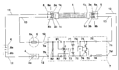
Figs. 1 to 3 schematically show a commercially available
fluorescent tube 1 in a straight design. The fluorescent tube
1 comprises two connector pins each 2a, 2b or 3a, 3b, respect-
ively, at both end caps la, 1b. The fluorescent tube 1 is
accommodated between two oppositely arranged brackets 8, 9 via
the connector pins 2a, 2b or 3a, 3b, respectively. On the one
hand, the brackets 8, 9 carry the fluorescent tube 1 mecha-
nically, on the other hand, the brackets 8, 9 comprise contact
receptacles 8a, 8b or 9a, 9b, respectively, in order to make
an electrical connection with the connector pins 2a, 2b or 3a,
3b, respectively, of the fluorescent tube 1. As is known,
CA 02338636 2001-O1-26
7
rotating brackets are a choice for this purpose, between which
the fluorescent tube is inserted vertically and by rotating
through an angle of 90° makes contact and is mechanically
locked. The connection of the fluorescent tube 1 with an
alternating current supply 6 is now made in a known manner
under interconnecting a ballast comprising a solenoid 4a,
which is simply referred to as reactance coil 4, as well as a
starter 5.
For this purpose, a contact receptacle 8a of a bracket 8 is
directly connected with a pole 6a of the alternating current
supply 6 according to Fig. 1. A contact receptacle 9a of the
other bracket 9 is connected with the other pole 6b of the
alternating current supply 6 via a second line 12, with the
reactance coil 4 being interconnected in the second line 12.
Moreover, a contact receptacle 8b of the one bracket 8 is
connected with a contact receptacle 9b of the other bracket 9
via a third line 13 in which the starter 5 is interconnected.
Due to the alternating current operation, it is of no signi-
ficance whether the connector pins 2a, 2b, or 3a, 3b, res-
pectively, of the fluorescent tube 1, the contact receptacles
8a, 8b or 9a, 9b, respectively, of the brackets 8, 9, or the
poles 6a, 6b of the alternating current supply 6 are inter-
changed among each other. For the same reason as shown in Fig.
2, the reactance coil 4 can be interconnected in the first
line 11, instead of in the second line 12 as shown in Fig. 1.
The inventive circuit arrangement is designed as a quadripole
7 which is interconnected in the second and third line 12, 13
according to Figs. 1 and 2. Thus the input terminals 7a, 7b of
the quadripole 7 form a series connection with the contact re-
ceptacles 8a, 8b of the one bracket or of the one thermionic
cathode lc, respectively, of the fluorescent tube 1, the re-
actance coil 4, and the starter 5, which is connected parallel
CA 02338636 2001-O1-26
8
to the alternating current supply 6. The output terminals 7c,
7d of the quadripole 7 are electrically connected with the
contact receptacles 9a, 9b of the other bracket 9, or the
other thermionic cathode 1d, respectively, of the fluorescent
tube 1.
Due to the alternating current operation, the same holds true
in the connection of the quadripole 7 in that both the poles
7a, 7b of the input terminals and the poles 7c, 7d of the out-
put terminals can be interchanged among each other. Likewise,
the series connection consisting of input terminals 7a, 7b,
thermionic cathode lc, reactance coil 4, and starter 5, can
have any order, for example the one shown in Fig. 2.
Furthermore, the quadripole 7 can be interconnected in the
first and third line 11, 13 as is shown in Fig. 3. In this
case the input terminals 7a, 7b of the quadripole 7 form a
series connection with the contact receptacles 9a, 9b of the
bracket 9, or the thermionic cathode 1d, respectively, of the
fluorescent tube 1, the reactance coil 4, and the starter 5,
which is connected in parallel to the alternating current
supply 6, and the output terminals 7c, 7d of the quadripole 7
are electrically connected with the contact receptacles 8a, 8b
of the bracket 8, or the thermionic cathode lc, respectively,
of the fluorescent tube 1.
According to Figs. 1 and 3, the starter 5 connected therein in
series with the input terminals 7a, 7b, is designed as an
electrical fuse 5a and thus serves as an additional protection
of the inventive circuit arrangement. Provided, this addition-
al protection is not desired or required, respectively, the
starter 5 must be bridged or short-circuited, respectively. If
the starter 5 is bridged by means of a line 5b it can also be
connected as is shown on Fig. 2 so that the output terminals
7c, 7d of the quadripole 7 and the starter 5 form a series
CA 02338636 2001-O1-26
9
connection which is electrically connected with the thermionic
cathode 1d of the fluorescent tube 1.
The quadripole 7 has an identical internal construction in the
sample circuits according to Figs. 1 to 3. The input side of
the quadripole 7 is supplied by the alternating current supply
6 so that its output side applies a high-frequency current IHe
to one thermionic cathode 1d or 1c, respectively, of the
fluorescent tube. In more detail, this results in the follow-
ing mode of function:
a.) One thermionic cathode lc or 1d, respectively, of the
fluorescent tube 1 is always connected in series with the in-
put terminals 7a, 7b of the quadripole 7 so that this thermi-
onic cathode always carries the input current of the quadri-
pole 7 and is thus preheated.
b.) Moreover, the thermionic cathode lc or 1d, respect-
ively, connected in series with the input terminals 7a, 7b of
the quadripole returns the high-frequency current IHe flowing
through the other thermionic cathode 1d or lc, respectively,
to the input side of the quadripole 7 and thus serves as
"virtual ground". For the high-frequency current IHF it is
basically irrelevant whether it flows directly to ground or
whether it flows to ground via the input side of the quadri-
pole 7. Due to the fact that the high-frequency current IHF in
this case flows to ground via the input side of the quadripole
7, a "short" path is advantageously provided so that the high-
frequency radiation is on the lowest possible level.
c.) Due to the fact that the reactance coil 4 is also
always connected in series with the input terminals 7a, 7b of
the quadripole 7, the solenoid 4a of the reactance coil 4
functions as a pre-filter which, on the one hand, optimises
power as well as the crest factor and, on the other hand,
CA 02338636 2001-O1-26
suppresses electromagnetic as well as high-frequency inter-
ferences.
d.) The input current of the quadripole 7 amounts to only
5 300 of the current consumption of a conventionally - i.e.
without the inventive circuit arrangement - operating fluor-
escent tube. In this manner, almost no power dissipation
occurs in the reactance coil 4 so that, furthermore, the re-
actance coil 4 remains cool during operation.
e.) A capacitor 83 is connected in parallel to the input
terminals 7a, 7b of the quadripole 7. The capacitor 83 to-
gether with the upstream reactance coil 4 serves as a com-
pensation and causes an increase of the power factor.
f.) A rectifier 70 is connected downstream of the input
terminals 7a, 7b of the quadripole 7, which is usually formed
by four diodes in a bridge circuit. Due to the fact that the
high-frequency current IHF superposes the input current as ex-
plained under b.), so-called "fast recovery" diodes are pre-
ferably used for the connection of the rectifier 70.
g.) Between the input terminals 7a, 7b of the quadripole
7 and the plus and minus output of the rectifier 70, prefer-
ably one capacitor each 81, 82 is connected or - in other
words - the rectifier 70 is quasi bridged by the capacitors
81, 82. This is always necessary if plain and thus low-cost
diodes are used for the connection of the rectifier 70 in lieu
of the "fast recovery" diodes mentioned under f.). The capa-
citors 81, 82 namely form a high-frequency short-circuit link
via which the high-frequency current IHF which superposes the
input current can flow off as explained under b.).
h.) Two smoothing capacitors 71, 72 which are connected
in series are connected parallel to the plus and minus output
CA 02338636 2001-O1-26
11
of the rectifier 70. The connection point of the smoothing
capacitors 71, 72 can be bridged to one of the input terminals
7a, 7b of the quadripole 7 by means of a line 73 in order to
enable the adaptation of the overall capacitance of the
smoothing capacitors 71, 72 to different voltages of the
alternating current supply 6, e.g. 110 V or 220 V.
i.) Between the plus output of the rectifier 70 and one
of the output terminals 7c, 7d of the quadripole 7 a coupling
capacitor 77 is connected so that the thermionic cathode 1d or
lc, respectively, to which the high-frequency current IHF is
applied is preheated during the starting phase of the fluor-
escent tube 1.
k.) Two transistors 75, 76 which are driven by a control
circuit 74, as well as a solenoid 79 form a high-frequency
stage for the generation of the high-frequency current IHE. The
high-frequency stage is connected between the plus and the
minus output of the rectifier 70 and the output terminals 7c,
7d of the quadripole 7. The control circuit 74 can, for
example, be an annular core transformer. However, in order to
reduce the power dissipation and the heat emission associated
therewith, it is advantageous to use a commercially available
driver IC for the control circuit 74 and to employ transistors
75, 76 of the MOSFET type.
l.) A blocking capacitor 78 is connected in series with
the output of the high-frequency stage or the solenoid 79,
respectively. The blocking capacitor 78 prevents the low-fre-
quency current from the alternating current supply 6 from
flowing through the fluorescent tube 1, which would expose the
high-frequency stage to the high voltage of the alternating
current supply 6 and thus damage same.
Fig. 4 schematically shows a sectional view of an inventive
device for connecting an inventive circuit arrangement with
CA 02338636 2001-O1-26
12
the fluorescent tube 1. The components 28 of the inventive
circuit arrangement are installed as an electr(on)ic circuit
in a known manner on a circuit board 26 which is accommodated
in a housing 27 for protection.
The inventive device comprises two connector pins 20a, 20b
which herein are electrically and mechanically accommodated in
the right hand bracket 9. The connector pins 20a, 20b are
formed as hollow pins. Coaxial with the connector pins 20a,
20b contact receptacles or connection sockets, respectively,
21a, 21b are arranged in the respective interior. The con-
nector pins 3a, 3b of the r.h. end cap 1b of the fluorescent
tube 1 are electrically and mechanically accommodated in the
contact receptacles or connection sockets, respectively, 21a,
21b. The connector pins 20a, 20b and the contact receptacles
or connection sockets, respectively, 21a, 21b are isolated
from each other by means of a layer 25a, 25b made from an
insulating material. The connector pins 20a, 20b as well as
the contact receptacles or connection sockets, respectively,
21a, 21b are secured or soldered, respectively, to a circuit
board 24. The circuit board 24 herein comprises (four) con-
ductors not shown in detail which lead to solder connections
from which the one end of a four-conductor cable 23 starts. At
its other end the cable 23 is connected with the circuit board
26 of the inventive circuit arrangement designed as the
quadripole 7 via solder connections. Thereby the connector
assignment is provided in such a manner that the connector
pins 20a, 20b are connected with the input terminals 7a, 7b of
the quadripole 7, and the contact receptacles or connection
sockets, respectively, 21a, 21b are connected with the output
terminals 7c, 7d of the quadripole 7. In this way - equivalent
to the sample circuits according to Figs. 1 and 2 - the input
terminals 7a, 7b of the quadripole 7 are connected in series
with the contact receptacles 8a, 8b of the 1.h. bracket 8, and
the output terminals 7c, 7d of the quadripole 7 are connected
CA 02338636 2001-O1-26
13
with the connectors pins 3a, 3b or the thermionic cathode lc,
respectively, at the r.h. end cap 1b of the fluorescent tube
1.
A housing 22 serves to accommodate the inventive device in a
protective manner. Due to the fact that the connector pins
20a, 20b and the contact receptacles or connection sockets,
respectively, 21a, 21b are arranged coaxially to one another,
the inventive device has such a narrow installation size that
the housing 22 fits into the gap between fluorescent tube 1
and bracket 9, which is provided anyway. It is understood that
one/both housings) 22, 27 can be equipped with connections so
that the cable 23 can be disconnected, for example, via plug-
in contacts or, if different cable lengths are required, be
replaced.
Compared to Fig. 4, the embodiment of the inventive circuit
arrangement according to Fig. 5 is arranged in the housing 22
of the inventive device or - in other words - both are
arranged in a common housing 22. Therein housing 22 comprises
an extension for accommodating the circuit board 27 of the
inventive circuit arrangement, which extends parallel to the
longitudinal axis L of the fluorescent tube 1. This results in
a particularly compact unit which can be retrofitted in a par-
ticularly simple manner, regardless of the physical conditions
prevailing in the electrical appliance in which it is employ-
ed. It is understood, that the circuit boards 24, 26 can be
combined to a common circuit board in alternative versions.
Finally, it should be noted that although the description of
the figures primarily deals with a straight design of the
fluorescent tube, it is nevertheless possible to utilise the
invention for other fluorescent tube designs as well, for
example, arc-shaped designs, as it is known for those with
skill in the art.