Language selection

Search

Patent 2338690 Summary

Third-party information liability

Some of the information on this Web page has been provided by external sources. The Government of Canada is not responsible for the accuracy, reliability or currency of the information supplied by external sources. Users wishing to rely upon this information should consult directly with the source of the information. Content provided by external sources is not subject to official languages, privacy and accessibility requirements.

Claims and Abstract availability

Any discrepancies in the text and image of the Claims and Abstract are due to differing posting times. Text of the Claims and Abstract are posted:

  • At the time the application is open to public inspection;
  • At the time of issue of the patent (grant).
(12) Patent Application: (11) CA 2338690
(54) English Title: ACOUSTIC DEVICE USING BENDING WAVE MODES
(54) French Title: DISPOSITIF ACOUSTIQUE UTILISANT DES MODES A ONDES DE FLEXION
Status: Deemed Abandoned and Beyond the Period of Reinstatement - Pending Response to Notice of Disregarded Communication
Bibliographic Data
(51) International Patent Classification (IPC):
  • H04R 7/06 (2006.01)
  • H04R 7/04 (2006.01)
(72) Inventors :
  • MORECROFT, DENIS (United Kingdom)
(73) Owners :
  • NEW TRANSDUCERS LIMITED
(71) Applicants :
  • NEW TRANSDUCERS LIMITED (United Kingdom)
(74) Agent: SMART & BIGGAR LP
(74) Associate agent:
(45) Issued:
(86) PCT Filing Date: 1999-07-26
(87) Open to Public Inspection: 2000-02-10
Availability of licence: N/A
Dedicated to the Public: N/A
(25) Language of filing: English

Patent Cooperation Treaty (PCT): Yes
(86) PCT Filing Number: PCT/GB1999/002221
(87) International Publication Number: WO 2000007408
(85) National Entry: 2001-01-26

(30) Application Priority Data:
Application No. Country/Territory Date
9816394.2 (United Kingdom) 1998-07-29

Abstracts

English Abstract


An acoustic device, e.g. a loudspeaker, has a transducer (38) coupled via a
highly perforate member (36) to an acoustically active area (39) that may be
in the form of a skin over part of the highly perforate member. The highly
perforate member (36) may be a mesh. Bending waves may be excited in the
highly perforate member (36) by the transducer (38) and sound emitted from the
acoustically active area (39).


French Abstract

L'invention porte sur un dispositif acoustique, par exemple un haut-parleur, muni d'un transducteur (38) relié par un élément fortement perforé (36) à une zone acoustiquement active (39) pouvant avoir la forme d'une peau disposée sur l'élément perforé (36), ce dernier (36) pouvant être maillé. On peut créer des ondes de flexion dans l'élément perforé à l'aide du transducteur (38) et du son émis par la zone acoustiquement active (39).

Claims

Note: Claims are shown in the official language in which they were submitted.

CLAIMS
1. An acoustic device comprising
a highly perforate member (16,26,36,46) capable of
sustaining bending wave action and accoustically
substantially inactive,
a transducer (18,28,38,48) directly connected to the
highly perforate member (16,26,36,46) for electrically
applying bending waves in the highly perforate member
(16,26,36,46) and
an acoustically active member (10,20,39) attached to
the highly perforate member (16,26,36,46) so as to be
coupled to the transducer (18,28,38,48) via the highly
perforate member (16, 26, 36, 46).
2. An acoustic device according to claim 1 wherein
the highly perforate member (26,36,46) is in the form of a
mesh having a regular array of holes.
3. An acoustic device according to claim 1 or 2
wherein the transducer (16,28,38,48) is spaced away from
the acoustically active member (10,20,39).
4. An acoustic device according to any preceding
claim wherein the acoustically active member (20,39) is a
skin covering the highly perforate member (26,36,46).
5. An acoustic device according to any preceding
claim wherein the highly perforate member (16,26,36,46) is
a distributed mode member shaped to have modes distributed
in frequency and over its area and to have preferential
locations for mounting a transducer.
6. An acoustic device according to claim 5 wherein

8
transducer (18,28,38,48) is mounted at one of said
preferential locations.
7. An acoustic device according to any preceding
claim wherein a visual display screen (40) is mounted over
a part of the highly perforate member (26, 36, 46), and the
acoustically active member (20,39) is provided on the
perimeter of the highly perforate member (26,36,46) around
the visual display screen (40).
8. An acoustic device according to any preceding
claim having a plurality of acoustically active areas (39)
provided on the highly perforate member (26,36,46).

Description

Note: Descriptions are shown in the official language in which they were submitted.


l2CV. \'UN : EF'A-Vll:f~NCIiFW «:-' : 17-1(~- 0 : 17 : 26 : U 1480 4f344 U5-~
+.f 9 89 2394465 : #I 4
17-10-2000 GB 009902221
1
TITLE : ?~COtJrSTIC DEVICE
DESCRIPTION
FIELD CF INV~,NTION
Tr~is invention relates to an acoustic device, in
particular to a loudspeaker that uses resonar_t bending wave
modes .
BACKGROUND TO THE INVENTIOIJ
Such resonant bending wave mode loudspeakers are
described in In~ernational patent applicatian Wo97/09642,
and several later patent applications all directed to
various types of distributed mode loudspeakers.
In sucl: prior distributed mode loudspeakers the
operative area produces sound over substantially its whole
surface. Indeed, normally the transducer position and shape
of the mEmber are selected so that the resonant modes
extend over the surface of the member so that sound is
produced evenly over the member avoiding 'hot spots'. The
member may comprise a cell;~lar or honeycomb matrix capable
of sustaining bending wave action. The matrix is
sandwiched between skins to which a transducer is mounted.
According to the ir_vention, there is provided an
CA 02338690 2001-O1-26 AM E N D E D S H E ET

IZCV. VON:Lt'A-Mt'EI~CHEN 1)2 :17-1C1- 0 : 17:ZG : C~1~80 4fr~4~0,-~ +4~;~3 89
'?399~~6Fs:ll a
17-10-2000 GB 009902221
2
acoustic device comprising a highly perforate tTtember
capable of sustaining bending wave action and acoLStically
s~~stanzially -r_active, a tra-lsducer directly connected to
the highly perforate member for el,eCtrically applying
S ;wending waves in tre highly perforate mer,~ber and an
acoustica:.ly active member attached to the highly perforate
me~rber so as to be coupled to the transducer via the highly
perforate member-
By Y!ighly perforate is meant a member that defines
holes in the member a.mou_~ntir_g to at Least Sod, preferably
70% or further preferably 80% of the surface area of the
member. The meatber can conveniently be in the form of a
mesh, with a regular array of '_zvles. The holes can be
square, circular, or indeed any shape.
The sour_d output from the h_ghly perforate member
itself can be extremely low. In a narma: distr=bused mode
loudspeaker, the sound ot;.tput from the back of tile speaker
and the sound output from the front are in antiphase, but
they do not interfere because the continuous panel and also
any baff_es present preven~s both sound waves from arriving
at the same poi7t. In the highly perforate member
envisaged by the present invent:.on, substantial
cancellation takes place. n~ioreover, only the solid area of
the member can emit sound, anG this can be as low as S% or
10% of the surface area of the rlember.
The acoustic device may be a loudspeaker.
The invention allows the lor_at~on of the transducer to
be spaced avaay from tre acoustically active area. This
CA 02338690 2001-O1-26 AM E N D E D S H E ET

RCV. VON:EPA-ViIWNCHI:N Q? :17-10- 0 : l7:~?Ei : t)14$l) 464405-~ +49 89
'.?.3~J944Ei~.o:~ t;
17-10-2000 GB 009902221
3
allows bending wave technology to be used in applicationE
where tY:e tra_~-sducer cannot be mounted immediately behind
the area intended for sound reproduction.
preferably, the acoustically active area comprises a
skin covex'ing the highly perforate member over the
acoustically active area. The skin serves to cover the
holes in the highly perforate member. The skin need not
itself be capable of bending wave action, because the
bend=ng waves are tran5rr.itted i:~ the highly perforate
merr3~er itself .
Preferably, the higrly perforate member and the
transducer location are as taught to be preferred for
distributed t7ode loudspeakers, for example in International
patent application w097/fl98c2. The aspect ratio may be
Lo 0.882 or 1 to 0.707 as taught in that application.
rr_ emi~odiments a visual display scx'een is mounted over
part of the highly perforate mesh, and the acoustically
active area is provided on the perimeter of the highly
perforate member around the visual display screen.
2U Depending on the geometry required, a plurality of
acoustically active areas may be provided on the highly
perforate member.
A highly perforate member of preferred shape can be
adapted to produce sound over any part of its surface by
prov_ding a Skin over that part. Tn this way, a single
highly perforate member can be readily adapted for use in a
number of different round reproducing devices without
hawing Lo manufacture a separate panel member for eacr
CA 02338690 2001-O1-26 AM E N D E D S H E ET

_Kt=V . vuw : tl'A-~'II.LNC:HN1~ U'? : 1 7 - LU- U : 17 : 27 . U 1486 4~644~05-
~ +4~9 8;3 ?399446;~ : # 7
17-10-2000 GB 009902221
4
aopl~~ation.
The i~:vertion also allows distributed mode sound to be
' output from an area shat is far from the preferred aspect
ratios. The ur~derlying highly perforate member can be of
such a preferred sr~ape, whereas the shape of acoustically
active member can be chosen freely.
Specific embodimert6 of the inven~ion will now be
described, purely by way of example, with reference to the
accompanying drawings in which:-
1o Figure ''_ shows a sczematic diagrar!~ of a loudspeaker
according to the inven~ion;
Figaxes 2a,2b and 2c show varicus transducer '_ocatiors
and aco:lstically active area locations on a member
according to the i:lvention;
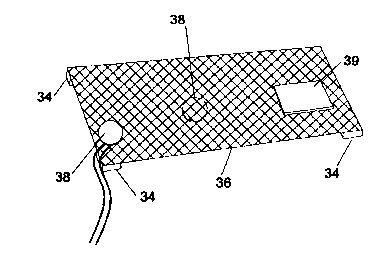
Fig~~re 3 shows an acoustic device according to the
in~rent ion, and
Figure 4 shows an acoustic device and display screen.
A loudspeaker comprises a resonant mode panel 10
having a core 12 and skins 13a and 13b_ R preferred
driving lecat~,on for the panel 10 is indicated at 15; the
panel and driving locations may be as described in
published Inte=national patent application W097/09842. A
bending wave exciting transducer 18 is coupled to the panel
10 by means of a coupling member 16 and sustains bending
2s waves without Itself providing Significant acoustic output.
The coup~er 16 has points 17 at the coupling location. Such
po~.nts particularly suit the launch of compression waves
into the member 10.
CA 02338690 2001-O1-26 AM E N D E D S H E ET

IZCV. VUN:EPA-IvIL:F~.CHEV U2 : 17- 10- U : 17:27 : 01.480 4~644U5--~ i49 89
?3SJ-944G5:#~ 8
17-10-2000 GB 009902221
In Figure 2, coupling members 26 are shown as being of
_.. perforate or open-work structure, i.e. a mesh. They are
proportioned for distributed mode perfonrance in accordance
with the teaching of W097%U9942, taking account of any
5 anisotropy of the bending stiffnesses or other parameters.
They may be made of any material, preferably a lightweight
stif f material each as alurlinium. since the coupling member
is perforate, the coupling member 26 does rot itself emit
significant quantities of so~~.nd. Various possible locations
1o for the transducer 28 are szoarn in the :figures. These
ocatior_s may either be peripheral locations or in-board
eccerar~.c locatians ae shown in figure 2a.
An acoustically active area in the form of a member 2o
is shown Coupled to the par~.el by a coupling 27. This may
i5 be an edge-to-edge ~:oupling as shown in Figure 2a, an in
board coupling as shown ~n F=gate 2b or a wholly internal
coupling as shown in Figure 2c.
Figure 3 shows a coupling member 36 with a transducer
3B mounted at locations either centrally 37 or
20 peripheral7.y. The transducer 38 is shown mounted at a
peripheral location. The perforate member is supported by
soft supports 34. A skin 39 is provided over a portion of
the perforate member and it is from the area of the skin
that sound is output. The skin 39 need r-ct have any
25 parti'ular physical requirements except that it must
respond to the bending of the underlying perforate member.
In particular, the sk;n 39 need not contribute to the
sti~fneas of the member 36 and
CA 02338690 2001-O1-26 AMENDED SHEET

WO 00/07408 PCT/GB99/02221
6
preferably does not do so. The skins may be provided at
any point over the surface of the member 36, or a plurality
of skins may be provided.
Figure 4 shows a beneficially proportioned perforate
member 46 with a transducer 48 mounted peripherally. Skins
39 are provided at four locations around the periphery of
the member 46. A display screen 40 _~s mounted above the
member 46.
The member 46 is mounted on substantially silent
vibrational members 44 at the corners of the members 46.
Such members 44 are preferably suitably resilient, and may
be mass provided at locations chosen to minimise acoustic
effects.
In general, the provision of a skin at desired
locations allows much greater flexibility in providing
sound output locations above the member. It is not
necessary that the active area itself is ideally
proportioned, as is the case for conventional distributed
mode loudspeakers.
CA 02338690 2001-O1-26

Representative Drawing
A single figure which represents the drawing illustrating the invention.
Administrative Status

2024-08-01:As part of the Next Generation Patents (NGP) transition, the Canadian Patents Database (CPD) now contains a more detailed Event History, which replicates the Event Log of our new back-office solution.

Please note that "Inactive:" events refers to events no longer in use in our new back-office solution.

For a clearer understanding of the status of the application/patent presented on this page, the site Disclaimer , as well as the definitions for Patent , Event History , Maintenance Fee  and Payment History  should be consulted.

Event History

Description Date
Inactive: IPC from MCD 2006-03-12
Application Not Reinstated by Deadline 2004-07-26
Time Limit for Reversal Expired 2004-07-26
Deemed Abandoned - Failure to Respond to Maintenance Fee Notice 2003-07-28
Inactive: Cover page published 2001-04-24
Inactive: First IPC assigned 2001-04-12
Letter Sent 2001-03-30
Inactive: Notice - National entry - No RFE 2001-03-30
Application Received - PCT 2001-03-28
Application Published (Open to Public Inspection) 2000-02-10

Abandonment History

Abandonment Date Reason Reinstatement Date
2003-07-28

Maintenance Fee

The last payment was received on 2002-06-11

Note : If the full payment has not been received on or before the date indicated, a further fee may be required which may be one of the following

  • the reinstatement fee;
  • the late payment fee; or
  • additional fee to reverse deemed expiry.

Please refer to the CIPO Patent Fees web page to see all current fee amounts.

Fee History

Fee Type Anniversary Year Due Date Paid Date
Basic national fee - standard 2001-01-26
Registration of a document 2001-01-26
MF (application, 2nd anniv.) - standard 02 2001-07-26 2001-07-25
MF (application, 3rd anniv.) - standard 03 2002-07-26 2002-06-11
Owners on Record

Note: Records showing the ownership history in alphabetical order.

Current Owners on Record
NEW TRANSDUCERS LIMITED
Past Owners on Record
DENIS MORECROFT
Past Owners that do not appear in the "Owners on Record" listing will appear in other documentation within the application.
Documents

To view selected files, please enter reCAPTCHA code :


To view images, click a link in the Document Description column. To download the documents, select one or more checkboxes in the first column and then click the "Download Selected in PDF format (Zip Archive)" or the "Download Selected as Single PDF" button.

List of published and non-published patent-specific documents on the CPD .

If you have any difficulty accessing content, you can call the Client Service Centre at 1-866-997-1936 or send them an e-mail at CIPO Client Service Centre.


Document
Description 
Date
(yyyy-mm-dd) 
Number of pages   Size of Image (KB) 
Representative drawing 2001-04-24 1 13
Abstract 2001-01-26 1 52
Description 2001-01-26 6 220
Claims 2001-01-26 2 54
Drawings 2001-01-26 4 110
Cover Page 2001-04-24 1 43
Reminder of maintenance fee due 2001-03-29 1 111
Notice of National Entry 2001-03-30 1 193
Courtesy - Certificate of registration (related document(s)) 2001-03-30 1 113
Courtesy - Abandonment Letter (Maintenance Fee) 2003-08-25 1 176
Reminder - Request for Examination 2004-03-29 1 116
PCT 2001-01-26 20 699
Fees 2001-07-25 1 37
Fees 2002-06-11 1 33