Language selection

Search

Patent 2338851 Summary

Third-party information liability

Some of the information on this Web page has been provided by external sources. The Government of Canada is not responsible for the accuracy, reliability or currency of the information supplied by external sources. Users wishing to rely upon this information should consult directly with the source of the information. Content provided by external sources is not subject to official languages, privacy and accessibility requirements.

Claims and Abstract availability

Any discrepancies in the text and image of the Claims and Abstract are due to differing posting times. Text of the Claims and Abstract are posted:

  • At the time the application is open to public inspection;
  • At the time of issue of the patent (grant).
(12) Patent Application: (11) CA 2338851
(54) English Title: OPTIC FIBER MANAGEMENT MODULE AND FURNITURE INCORPORATING SAME
(54) French Title: MODULE DE GESTION DE FIBRES OPTIQUES ET MOBILIER EQUIPE D'UN TEL MODULE
Status: Deemed Abandoned and Beyond the Period of Reinstatement - Pending Response to Notice of Disregarded Communication
Bibliographic Data
(51) International Patent Classification (IPC):
  • G02B 6/46 (2006.01)
  • A47B 97/00 (2006.01)
(72) Inventors :
  • FINGLER, LAURENCE H. (Canada)
  • FINGLER, L. SCOTT (Canada)
  • LAYCOCK, GEOFFREY P. (Canada)
(73) Owners :
  • FIBER CONNECTIONS INC.
(71) Applicants :
  • FIBER CONNECTIONS INC. (Canada)
(74) Agent: MARKS & CLERK
(74) Associate agent:
(45) Issued:
(22) Filed Date: 2001-02-28
(41) Open to Public Inspection: 2001-09-03
Availability of licence: N/A
Dedicated to the Public: N/A
(25) Language of filing: English

Patent Cooperation Treaty (PCT): No

(30) Application Priority Data:
Application No. Country/Territory Date
60/186,903 (United States of America) 2000-03-03

Abstracts

English Abstract


An optic fiber management module includes an optic fiber distributor
to receive a multi-fiber optic cable and to fan out individual optic fibers of
the cable to
individual first connectors. A plurality of optic fiber sources each of which
includes
an optic fiber is also provided. Each optic fiber has one end coupled to a
respective
one of the first connectors and an opposite end having a second connector
thereon.
Each optic fiber is extendible from the respective first connector to an end
use thereby
to bring the second connector to the end use. A furniture system incorporating
the
optic fiber management module is also provided.


Claims

Note: Claims are shown in the official language in which they were submitted.


-6-
We Claim:
1. An optic fiber management module comprising:
an optic fiber distributor to receive a multi-fiber optic cable and to fan
out individual optic fibers of said cable to individual first connectors; and
a plurality of optic fiber sources each of which includes an optic fiber,
each optic fiber having one end coupled to a respective one of said first
connectors
and an opposite end having a second connector thereon, each said optic fiber
being
extendible from said respective first connector to an end use thereby to bring
the
second connector to said end use.
2. An optic fiber management module as defined in claim 1 wherein the
one end of each optic fiber has a connector thereon to mate releasably with
said
respective one of said first connectors.
3. An optic fiber management module as defined in claim 2 wherein each
of said optic fiber sources includes a spool loaded with a length of optic
fiber.
4. An optic fiber management module as defined in claim 3 further
including a bracket on which said optic fiber distributor and optic fiber
sources are
mounted.
5. An optic fiber management module as defined in claim 4 further
including a plurality of posts extending from said bracket, each of said posts
removably supporting at least one spool.
6. An optic fiber management module as defined in claim 5 wherein each
post supports a plurality of spools.
7. An optic fiber management module as defined in claim 3 wherein each
spool is loaded with a different length of optic fiber.

-7-
8. An optic fiber management module as defined in claim 4 wherein said
fiber optic distributor includes a third connector to receive releasably said
multi-fiber
optic cable and a plurality of optic fibers interconnecting said third
connector and said
first connectors.
9. An optic fiber management module as defined in claim 8 wherein said
first and second connectors are MTRJ connectors arid wherein said third
connector is
an MTP connector.
10. A furniture system comprising:
a plurality of workstations; and
an optic fiber management module mounted on one of said
workstations, said optic fiber management module including:
a mounting bracket;
an optic fiber distributor on said mounting bracket to receive a
multi-fiber optic cable and to fan out individual optic fibers of said cable
to individual
first connectors; and
a plurality of optic fiber sources on said mounting bracket each
of which includes an optic fiber, each optic fiber having one end coupled to a
respective one of said first connectors and an opposite end having a second
connector
thereon, each said optic fiber extending from said respective first connector
to a
respective one of said workstations thereby to bring the second connector to
said
respective one of said workstations.
11. A furniture system as defined in claim 10 wherein said workstations
include wiring channels to accommodate said optic fibers.
12. A furniture system as defined in claim 11 wherein the one end of each
optic fiber has a connector thereon to mate releasably with said respective
one of said
first connectors.

-8-
13. A furniture system as defined in claim 12 wherein each of said optic
fiber sources includes a spool loaded with a length of optic fiber.
14. A furniture system as defined in claim 13 further including a plurality
of posts extending from said bracket, each of said posts removably supporting
at least
one spool.
15. A furniture system as defined in claim 14 wherein each post supports a
plurality of spools.
16. A furniture system as defined in claim 13 wherein said fiber optic
distributor includes a third connector to receive releasably said multi-fiber
optic cable
and a plurality of optic fibers interconnecting said third connector and said
first
connectors.
17. A furniture system as defined in claim 17 wherein said first and second
connectors are MTRJ connectors and wherein said third connector is a MTP
connector.

Description

Note: Descriptions are shown in the official language in which they were submitted.


CA 02338851 2001-02-28
OPTIC FIBER MANAGEMENT MODULE AND
FURNITURE INCORPORATING SAME
FIELD OF THE INVENTION
The present invention relates to fiber optics and in particular to an
optic fiber management module to be installed within a furniture system to
distribute
optical fiber to individual workstations. The present invention also relates
to a
furniture system incorporating an optic fiber management module.
BACKGROUND OF THE INVENTION
In today's office environment, portable workstations are replacing
permanent walled offices. Workstations of this nature allow offices to be
reconfigured quickly to meet changing needs. In order to be effective, these
portable
workstations need to provide suitable connections for workstation equipment
such as
computers, telephones etc. to communication networks. Unfortunately, current
furniture system designs have failed to keep pace with office environment
needs.
It is therefore an object of the present invention to provide a novel
optic fiber management module and a furniture system incorporating the same.
SUMMARY OF THE INVENTION
According to one aspect of the present invention there is provided an
optic fiber management module comprising:
an optic fiber distributor to receive a mufti-fiber optic cable and to fan
out individual optic fibers of said cable to individual first connectors; and
a plurality of optic fiber sources each of which includes an optic fiber,
each optic fiber having one end coupled to a respective one of said first
connectors
and an opposite end having a second connector thereon, each said optic fiber
being
extendible from said respective first connector to an end use thereby to bring
the
second connector to said end use.
Preferably, the one end of each optic fiber has a connector thereon to
mate releasably with the respective one of the first connectors. It is also
preferred that
each of the optic fiber sources includes a spool loaded with a length of optic
fiber. In
one embodiment, the optic fiber management module further includes a bracket
on
which the optic fiber distributor and optic fiber sources are mounted. A
plurality of

CA 02338851 2001-02-28
-2-
posts extends from the bracket, with each post removably supporting a
plurality of
spools.
Preferably, the fiber optic distributor includes a third connector to
receive releasably the multi-fiber optic cable and a plurality of optic fibers
interconnecting the third connector and the first connectors. It is also
preferred that
the first and second connectors are MTJR connectors and the third connector is
an
MTP connector.
According to another aspect of the present invention there is provided
a furniture system comprising:
a plurality of workstations; and
an optic fiber management module mounted on one of said
workstations, said optic fiber management module including:
a mounting bracket;
an optic fiber distributor on said mounting bracket to receive a
1 S multi-fiber optic cable and to fan out individual optic fibers of said
cable to individual
first connectors; and
a plurality of optic fiber sources on said mounting bracket each
of which includes an optic fiber, each optic fiber having one end coupled to a
respective one of said first connectors and an opposite end having a second
connector
thereon, each said optic fiber extending from said respective first connector
to a
respective one of said workstations thereby to bring the second connector to
said
respective one of said workstations.
The present invention provides advantages in that the optic fiber
management module allows furniture systems to be wired easily and effectively
with
optic fiber thereby to facilitate the connection of workstation equipment to
communication networks.
BRIEF DESCRIPTION OF THE DRAWINGS
An embodiment of the present invention will now be described more
fully with reference to the accompanying drawings in which:
Figure 1 is a perspective view of an optic fiber management module in
accordance with the present invention;

CA 02338851 2001-02-28
-3-
Figure 2 is a perspective view of a mounting bracket forming part of
the optic fiber management module of Figure 1;
Figure 3 is a perspective view of an optic fiber distributor forming part
of the optic fiber management module of Figure 1;
Figure 4 is a side elevational view of a furniture system incorporating
the optic fiber management module of Figure l; and
Figure 5 is a side elevational view of another furniture system
incorporating the optic fiber management module of Figure 1.
1 O DETAILED DESCRIPTION OF THE PREFERRED EMBODIMENT
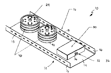
Turning now to Figures 1 to 3, an optic fiber management module in
accordance with the present invention is shown and is generally identified by
reference numeral 10. As can be seen, optic fiber management module 10
includes a
steel mounting bracket 12 having a rectangular base 14 with flanges 16 running
along
its opposite major side edges. Spaced, elongate mounting holes 18 are provided
in the
flanges 16 to enable the bracket 12 to be secured to a workstation.
A pair of upright spaced, hollow spool posts 24 is welded to the base
14 nearer one of its ends. A pair of upstanding tabs 26 also extends from the
base 14
nearer the other of its ends. Each tab 26 has a hole 28 provided therethrough.
Secured to the tabs 26 by way of fasteners (not shown) is an optic fiber
distribution
module 30 designed to "fan out" optic fiber from a multi-fiber optic cable.
The optic fiber distribution module 30 includes an optic fiber
distributor 34 as best illustrated in Figure 3. Optic fiber distributor 34
includes a body
34a having an MTP connector 36 one on side of the body 34a. A plurality, (in
this
example twelve), of MTRJ connectors 38 is provided on an opposite side of the
body
34a. Optic fibers (not shown) within the body 34a connect the MTP connector 36
to
the individual MTRJ connectors 38. In this manner, the individual fibers of a
multi-
fiber optic cable coupled to the MTP connector 36 can be fanned out to the
individual
MTRJ connectors 38. A shallow U-shaped cover 32 overlies the optic fiber
distributor 34 in a manner so that the MTP connector 36 and the MTRJ
connectors 38
remain exposed.

CA 02338851 2001-02-28
-4-
A plurality of optic fiber spools 40 are removably loaded onto each of
the spool posts 24. In this particular example, three optic fiber spools 40
are shown
loaded onto each spool post 24 for illustrative purposes. Each optic fiber
spool 40 is
preloaded with an appropriate length of optic fiber 42. The ends of each optic
fiber
42 have MTRJ connectors fitted thereon. In this way, one end of each optic
fiber 42
can be releasably coupled to an MTRJ connector 38. Each optic fiber 42 can be
unwound from the spool 40 so that its other end terminates at a desired
location.
In the present embodiment, the optic fiber management module 30 is
designed to be used with a furniture system to allow the individual fibers in
a multi-
fiber optic cable to be fanned out to individual workstations of the furniture
system.
Turning now to Figure 4, a furniture system 50 including a plurality of
workstations 52 is shown. The optic fiber management module 10 is secured to
the
back of one of the workstations 52 via fasteners (not shown) passing through
the
mounting holes 18 in the flanges 16 of bracket 12.
Spools 40 with the appropriate lengths of optic fiber 42 necessary to
wire the workstations 52 are loaded onto the spool posts 24. Each spool 40 is
associated with one of the workstations 52 and includes an appropriate length
of optic
fiber sufficient to extend between its associated workstation 52 and one of
the MTRJ
connectors 38. The optic fiber 42 loaded on each spool 40 is unreeled from the
spool
40 so that one of its ends is positioned at its associated workstation 52. As
the optic
fiber 42 is unreeled from the spool 40, it is laid in wiring channels 56
provided by the
workstations. The end of the optic fiber 42 is then terminated either at an
MTRJ
connector 58 provided on the workstation 52 or at an MTRJ connector on
workstation
equipment (not shown). Although not shown, a grommet accommodated by the
workstation 52 is used to secure the optic fiber 42 to the workstation 52. The
other
end of the optic fiber 42 is unhooked from the spool 40 and its MTRJ connector
is
coupled to one of the MTRJ connectors 38 of the optic fiber distributor 34.
With the
furniture system 50 wired in this manner, the optic fiber distribution module
30 can be
coupled to a computer server 60 via mufti-fiber optic cable 64 extending
between a
zone box 62 and the MTP connector 36 and between the zone box 62 and the
computer server 60.

CA 02338851 2001-02-28
- S -
In an alternative embodiment as shown in Figure 5, each spool 40 is
loaded with the same length of optic fiber 42. A bracket (not shown) having a
plurality of MTRJ connectors thereon is secured to the first workstation 52.
The optic
fiber 42 of each spool 40 is coupled to one of the MTRJ connectors on the
bracket and
to one.of the MTRJ connectors 38 of the optic fiber distributor 34. Standard
patch
cords are then laid in the wiring channels 56 and run from the MTRJ connectors
on
the bracket to the individual workstations 52.
As will be appreciated, the optic fiber management module 10 allows
furniture systems to be wired with optic fiber in an easy and efficient
manner.
Although a preferred embodiment of the present invention has been described,
those
of skill in the art will appreciate that variations and modifications may be
made
without departing from the spirit and scope thereof as defined by the appended
claims.

Representative Drawing
A single figure which represents the drawing illustrating the invention.
Administrative Status

2024-08-01:As part of the Next Generation Patents (NGP) transition, the Canadian Patents Database (CPD) now contains a more detailed Event History, which replicates the Event Log of our new back-office solution.

Please note that "Inactive:" events refers to events no longer in use in our new back-office solution.

For a clearer understanding of the status of the application/patent presented on this page, the site Disclaimer , as well as the definitions for Patent , Event History , Maintenance Fee  and Payment History  should be consulted.

Event History

Description Date
Time Limit for Reversal Expired 2006-02-28
Application Not Reinstated by Deadline 2006-02-28
Deemed Abandoned - Failure to Respond to Maintenance Fee Notice 2005-02-28
Letter Sent 2001-10-19
Inactive: Adhoc Request Documented 2001-10-05
Inactive: Single transfer 2001-09-07
Inactive: Correspondence - Formalities 2001-09-07
Inactive: Compliance - Formalities: Resp. Rec'd 2001-09-04
Inactive: Correspondence - Formalities 2001-09-04
Application Published (Open to Public Inspection) 2001-09-03
Inactive: Cover page published 2001-09-02
Inactive: Incomplete 2001-08-14
Inactive: First IPC assigned 2001-04-20
Inactive: IPC assigned 2001-04-20
Application Received - Regular National 2001-03-29
Filing Requirements Determined Compliant 2001-03-29
Inactive: Filing certificate - No RFE (English) 2001-03-29

Abandonment History

Abandonment Date Reason Reinstatement Date
2005-02-28

Maintenance Fee

The last payment was received on 2004-03-01

Note : If the full payment has not been received on or before the date indicated, a further fee may be required which may be one of the following

  • the reinstatement fee;
  • the late payment fee; or
  • additional fee to reverse deemed expiry.

Patent fees are adjusted on the 1st of January every year. The amounts above are the current amounts if received by December 31 of the current year.
Please refer to the CIPO Patent Fees web page to see all current fee amounts.

Fee History

Fee Type Anniversary Year Due Date Paid Date
Registration of a document 2001-02-28
Application fee - small 2001-02-28
2001-09-04
MF (application, 2nd anniv.) - small 02 2003-02-28 2003-02-28
MF (application, 3rd anniv.) - small 03 2004-03-01 2004-03-01
Owners on Record

Note: Records showing the ownership history in alphabetical order.

Current Owners on Record
FIBER CONNECTIONS INC.
Past Owners on Record
GEOFFREY P. LAYCOCK
L. SCOTT FINGLER
LAURENCE H. FINGLER
Past Owners that do not appear in the "Owners on Record" listing will appear in other documentation within the application.
Documents

To view selected files, please enter reCAPTCHA code :


To view images, click a link in the Document Description column. To download the documents, select one or more checkboxes in the first column and then click the "Download Selected in PDF format (Zip Archive)" or the "Download Selected as Single PDF" button.

List of published and non-published patent-specific documents on the CPD .

If you have any difficulty accessing content, you can call the Client Service Centre at 1-866-997-1936 or send them an e-mail at CIPO Client Service Centre.


Document
Description 
Date
(yyyy-mm-dd) 
Number of pages   Size of Image (KB) 
Representative drawing 2001-08-22 1 14
Drawings 2001-09-03 5 110
Description 2001-02-27 5 226
Claims 2001-02-27 3 96
Drawings 2001-02-27 5 115
Abstract 2001-02-27 1 17
Filing Certificate (English) 2001-03-28 1 164
Courtesy - Certificate of registration (related document(s)) 2001-10-18 1 113
Reminder of maintenance fee due 2002-10-28 1 109
Courtesy - Abandonment Letter (Maintenance Fee) 2005-04-24 1 174
Reminder - Request for Examination 2005-10-30 1 115
Correspondence 2001-03-28 1 29
Correspondence 2001-08-12 1 19
Correspondence 2001-09-06 2 78
Correspondence 2001-09-03 6 155
Fees 2003-02-27 1 52
Fees 2004-02-29 1 51