Language selection

Search

Patent 2338853 Summary

Third-party information liability

Some of the information on this Web page has been provided by external sources. The Government of Canada is not responsible for the accuracy, reliability or currency of the information supplied by external sources. Users wishing to rely upon this information should consult directly with the source of the information. Content provided by external sources is not subject to official languages, privacy and accessibility requirements.

Claims and Abstract availability

Any discrepancies in the text and image of the Claims and Abstract are due to differing posting times. Text of the Claims and Abstract are posted:

  • At the time the application is open to public inspection;
  • At the time of issue of the patent (grant).
(12) Patent Application: (11) CA 2338853
(54) English Title: ROOF VENTS
(54) French Title: EXUTOIRES EN TOITURE
Status: Deemed Abandoned and Beyond the Period of Reinstatement - Pending Response to Notice of Disregarded Communication
Bibliographic Data
(51) International Patent Classification (IPC):
  • E04D 13/17 (2006.01)
  • E04D 3/06 (2006.01)
  • E04D 3/08 (2006.01)
  • E04D 13/03 (2006.01)
  • F24F 7/02 (2006.01)
(72) Inventors :
  • RICHARDSON, CHRISTOPHER (United Kingdom)
(73) Owners :
  • ULTRAFRAME (UK) LIMITED
(71) Applicants :
  • ULTRAFRAME (UK) LIMITED (United Kingdom)
(74) Agent: MARKS & CLERK
(74) Associate agent:
(45) Issued:
(22) Filed Date: 2001-02-28
(41) Open to Public Inspection: 2001-08-28
Examination requested: 2006-02-15
Availability of licence: N/A
Dedicated to the Public: N/A
(25) Language of filing: English

Patent Cooperation Treaty (PCT): No

(30) Application Priority Data:
Application No. Country/Territory Date
0004597.1 (United Kingdom) 2000-02-28

Abstracts

English Abstract


A roof vent suitable for a conservatory roof of the type comprising glazing
bars supporting glazing panels therebetween, the roof vent comprises a
surround mountable between a pair of glazing bars and a cover for the surround
and hingedly connected thereto.


Claims

Note: Claims are shown in the official language in which they were submitted.

6
Claims:
1. A roof vent suitable for a conservatory roof of the type comprising glazing
bars supporting glazing panels therebetween, the roof vent comprising a
surround mountable between a pair of glazing bars and a cover for the surround
and hingedly connected thereto.
2. A roof vent as claimed in claim 1, wherein the surround is mounted
between the glazing bars in a similar fashion to the glazing panels.
3. A roof vent as claimed in claim 2, wherein the surround has sides
capable of coupling to the glazing bars using one or more coupling formations
of
the glazing bars.
4. A roof vent as claimed in claim 3, wherein the surround and glazing bars
have mutually engageable channel slots on their sides.
5. A roof vent as claimed in claim 4, wherein the surround can be slid into
place between the glazing bars.
6. A roof vent as claimed in claim 1 including a spacer box at its rear so
that
the roof vent is spaced from a wall or other supporting structure for the
roof.
7. A roof vent as claimed in claim 6, wherein the spacer box has
perforations to allow heat to dissipate.
8. A roof vent as claimed in claim 7, wherein the spacer box has end panels
and the perforations are in the end panels of the spacer box.
9. A conservatory roof including a roof vent as claimed in claim 1.

Description

Note: Descriptions are shown in the official language in which they were submitted.


CA 02338853 2001-02-28
TITLE: ROOF VENTS
DESCRIPTION
An object of this invention is to provide an improved roof vent suitable for
inclusion in a conservatory roof.
According to this invention there is provided a roof vent suitable for a
conservatory roof of the type comprising glazing bars supporting glazing
panels
therebetween, the roof vent comprising a surround mountable between a pair of
glazing bars and a cover for the surround and hingedly connected thereto.
The surround is preferably mounted between the glazing bars in a similar
fashion to the glazing panels. In other words it is preferable for the
surround to
have sides capable of coupling to the glazing bars using one or more coupling
formations of the glazing bars. In a preferred embodiment, the surround and
glazing bars have mutually engageable channel slots on their sides, preferably
so that the surround can be slid into place between the glazing bars.
The roof vent of the invention preferably includes a spacer box at its rear
so that the roof vent is spaced from a wall or other supporting structure for
the
roof. The spacer box preferably has perforations, ideally ifl end panels, to
allow
heat to dissipate.
Other preferred features and advantages of the roof vent of the invention
will now be further described, by way of example only, with reference to the
accompanying drawings, in which:

CA 02338853 2001-02-28
2
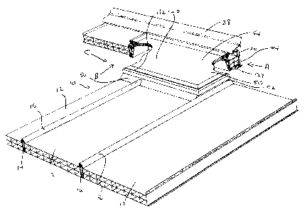
Figure 7 shows a conservatory roof with a roof vent of the invention
partially cut away.
Figure 2 is a view in the direction of arrow A of Figure 1;
Figure 3 is a view in the direction of arrow B of Figure 1;
Figure 4 is a view in the direction of arrow C of Figure 1;
Figure 5 is a perspective view from one corner of a roof vent surround;
Figure 6 is aside view of the roof vent surround of Figure 5;
Figure 7 shows details of the roof vent surround; and
Figure 8 is an exploded view of a spacer component for the roof vent
surround.
Referring to the accompanying drawings, a conservatory roof 10
supported at its upper side from a wall or other suitable structure comprises
glazing panels 12, typically of PVC or -polycarbonate, supported between
glazing bars 14 and held down by cappings 16 retained by the glazing bars.
Only the upper end of the roof is shown and the upper ends of the glazing bars
and panels are supported in channel member 20 slidabfy mounted on spaced
brackets 22 screwed to the wall. The channel member 20 has a top side 24
ending in a barb 26 onto which is push fitted a top cover 28 that includes a
depending web 30 with gasket material 32 on its end to seaa against the
glazing
panels 12 and near its forward end a rain baffle 34 that has a flexible hinge
36 to
urge it downwards onto the top glazing bars cappings 16.
The roof includes a vent 50 comprising a surround 52 and a cover 54
hingedly mounted on one side of the surround. The surround is constructed from

CA 02338853 2001-02-28
3
four sections of a u-PVC extrusion mitred and heat welded together to form a
rectangle. The surround sides 56 are slightly different from its ends 58 as
will be
described later. The surround has a lower part with sloping internal faces 60.
The surround has an upper part and shaped outer faces to provide locations for
attachment thereto of other components of the roof vent system and for
attachment of the surround to the existing roof structure.
The outside of the surround has from the bottom upward a flange 64
above which is a recess fib then a slot 68 before it is stepped nwards forming
a
ledge 70 with a rib 72 thereon. A further slot 73 is spaced above the ledge
70.
From the ledge, the surround extends upwards to a curved hinge part 74. The
surround then has a top surface 76 with a slot 78 for receiving a gasket strip
80.
The sides 56 of the surround 52 have extending upwards from the end of
the ledge an inverted channel section flange 82, which is a sliding fit into a
side
channel 84 of the glazing bar 14 to which normally a glazing aanel couples.
That enables the surround 52 to be sufficiently wide to occupy the width of
one
or even two glazing panels because it can be slid into position between
glazing
bars.
The surround 52 has on its front a sealing flap 84, that overlies the
glazing panel or panels 12 abutting the surround. A triangular section trim 86
is
pushed into the front of the surround and has top and bottom extensions 88, 90
that locate in the slot 73 and over the rib 72 respectively to hold the
sealing flap
84 down on the glazing panels.
The vent surround 52 does not occupy the whole length of the roof and so

CA 02338853 2001-02-28
4
provision has to be made for connection of a shorter glazing bar 14 length to
the
front of the surround when the vent is of double panel width. A shaped steel
reinforcing strip 92 locates in the channel 66 to give the front of the
surround
strength and is held an place by screws 96 at opposite ends and by, a central
bracket 98 having a spigot 100 that locates in the duct 102 of the glazing
bar,
where it is bolted in place.
At the rear of the vent surround, so that it is spaced from the capping to
allow the vent cover 54 to open, there is a spaced box 104 (see figure 8). The
spacer box 104 is formed as a rectangular section extrusion with internal
cross
webs 106, 107 and has end caps 108 that are perforated to allow heat to
dissipate from it. The spacer boxer 104 is secured in the channel 20 by means
of screws 108, through the lower side 110 of the channel.
The spacer box 104 has oppositely orientated v-shaped ribs 112 on its
front face 114, that snap fit into the recess 66 in the rear face of the
surround.
Above those ribs is a barbed projection 116 which fits the slot 68 in the rear
face
of the surround. Finally the top front edge of the spacer box has a co-
extruded or
bonded gasket 120 thereon to mask the joint between the spacer box and the
surround.
The channel member 20 has undercladding 122 located -#hereon that has
on a front top edge a co-exfiruded or borded gasket 124 to form a seal against
the underside of the spacer box.
The free end of the bottom ledge 64 of the surround is shaped to receive
a sealing strip 130 for between the ledge 64 and the underside of surrounding

CA 02338853 2001-02-28
components of the roof.
The cover 54 of the vent has outer and inner parts 132, 134 respectively,
that trap a glazing panel therebetween. Around the inside of the outer part
132 is
a slot 136 and the inner part is of L-section with its upstand 138 barbed so
as to
be a press fit into the slot, the other limb of the L-section serving as on a
ledge
for glazing panel 14.
The outer cover part has an overhang 142 on the underside of which is a
T-section slot 144 which slidingly retains an aluminium hinge part 146 that
engages around the hinge part of the vent surround to allow the cover to be
opened and closed. In the slot 78 in the top of the surround 52 is the gasket
strip
80 for sealing between the cover and the surround.
By having the vent surround slide between glazing bars the vent cover
can be made wider than was hitherto possible, which provides for improved
ventilation and aesthetic appearance.

Representative Drawing
A single figure which represents the drawing illustrating the invention.
Administrative Status

2024-08-01:As part of the Next Generation Patents (NGP) transition, the Canadian Patents Database (CPD) now contains a more detailed Event History, which replicates the Event Log of our new back-office solution.

Please note that "Inactive:" events refers to events no longer in use in our new back-office solution.

For a clearer understanding of the status of the application/patent presented on this page, the site Disclaimer , as well as the definitions for Patent , Event History , Maintenance Fee  and Payment History  should be consulted.

Event History

Description Date
Application Not Reinstated by Deadline 2008-02-28
Time Limit for Reversal Expired 2008-02-28
Deemed Abandoned - Failure to Respond to Maintenance Fee Notice 2007-02-28
Inactive: IPC from MCD 2006-03-12
Letter Sent 2006-03-10
All Requirements for Examination Determined Compliant 2006-02-15
Request for Examination Requirements Determined Compliant 2006-02-15
Request for Examination Received 2006-02-15
Application Published (Open to Public Inspection) 2001-08-28
Inactive: Cover page published 2001-08-27
Letter Sent 2001-06-21
Inactive: Single transfer 2001-05-25
Inactive: Correspondence - Formalities 2001-05-25
Inactive: First IPC assigned 2001-04-27
Inactive: IPC assigned 2001-04-27
Inactive: Filing certificate - No RFE (English) 2001-03-29
Filing Requirements Determined Compliant 2001-03-29
Application Received - Regular National 2001-03-29

Abandonment History

Abandonment Date Reason Reinstatement Date
2007-02-28

Maintenance Fee

The last payment was received on 2006-02-27

Note : If the full payment has not been received on or before the date indicated, a further fee may be required which may be one of the following

  • the reinstatement fee;
  • the late payment fee; or
  • additional fee to reverse deemed expiry.

Please refer to the CIPO Patent Fees web page to see all current fee amounts.

Fee History

Fee Type Anniversary Year Due Date Paid Date
Registration of a document 2001-02-28
Application fee - standard 2001-02-28
MF (application, 2nd anniv.) - standard 02 2003-02-28 2003-01-29
MF (application, 3rd anniv.) - standard 03 2004-03-01 2004-02-11
MF (application, 4th anniv.) - standard 04 2005-02-28 2005-02-04
Request for examination - standard 2006-02-15
MF (application, 5th anniv.) - standard 05 2006-02-28 2006-02-27
Owners on Record

Note: Records showing the ownership history in alphabetical order.

Current Owners on Record
ULTRAFRAME (UK) LIMITED
Past Owners on Record
CHRISTOPHER RICHARDSON
Past Owners that do not appear in the "Owners on Record" listing will appear in other documentation within the application.
Documents

To view selected files, please enter reCAPTCHA code :


To view images, click a link in the Document Description column. To download the documents, select one or more checkboxes in the first column and then click the "Download Selected in PDF format (Zip Archive)" or the "Download Selected as Single PDF" button.

List of published and non-published patent-specific documents on the CPD .

If you have any difficulty accessing content, you can call the Client Service Centre at 1-866-997-1936 or send them an e-mail at CIPO Client Service Centre.


Document
Description 
Date
(yyyy-mm-dd) 
Number of pages   Size of Image (KB) 
Representative drawing 2001-08-15 1 24
Description 2001-02-28 5 187
Abstract 2001-02-28 1 10
Claims 2001-02-28 1 33
Drawings 2001-02-28 6 268
Drawings 2001-05-29 7 196
Cover Page 2001-08-17 1 47
Filing Certificate (English) 2001-03-29 1 164
Courtesy - Certificate of registration (related document(s)) 2001-06-21 1 112
Reminder of maintenance fee due 2002-10-29 1 109
Reminder - Request for Examination 2005-10-31 1 115
Acknowledgement of Request for Examination 2006-03-10 1 177
Courtesy - Abandonment Letter (Maintenance Fee) 2007-04-25 1 174
Correspondence 2001-03-29 1 28
Correspondence 2001-05-25 8 217
Fees 2006-02-27 1 48