Language selection

Search

Patent 2339208 Summary

Third-party information liability

Some of the information on this Web page has been provided by external sources. The Government of Canada is not responsible for the accuracy, reliability or currency of the information supplied by external sources. Users wishing to rely upon this information should consult directly with the source of the information. Content provided by external sources is not subject to official languages, privacy and accessibility requirements.

Claims and Abstract availability

Any discrepancies in the text and image of the Claims and Abstract are due to differing posting times. Text of the Claims and Abstract are posted:

  • At the time the application is open to public inspection;
  • At the time of issue of the patent (grant).
(12) Patent: (11) CA 2339208
(54) English Title: AN AIRCRAFT FIN AND RUDDER
(54) French Title: DERIVE ET GOUVERNAIL POUR AERONEF
Status: Expired and beyond the Period of Reversal
Bibliographic Data
(51) International Patent Classification (IPC):
  • B64C 9/00 (2006.01)
  • B64C 5/06 (2006.01)
(72) Inventors :
  • HYDE, LESLIE LEIGH (United Kingdom)
(73) Owners :
  • AIRBUS OPERATIONS LIMITED
(71) Applicants :
  • AIRBUS OPERATIONS LIMITED (United Kingdom)
(74) Agent: SMART & BIGGAR LP
(74) Associate agent:
(45) Issued: 2007-11-13
(86) PCT Filing Date: 1999-08-03
(87) Open to Public Inspection: 2000-02-17
Examination requested: 2004-03-22
Availability of licence: N/A
Dedicated to the Public: N/A
(25) Language of filing: English

Patent Cooperation Treaty (PCT): Yes
(86) PCT Filing Number: PCT/GB1999/002568
(87) International Publication Number: WO 2000007875
(85) National Entry: 2001-01-31

(30) Application Priority Data:
Application No. Country/Territory Date
9816938.6 (United Kingdom) 1998-08-05

Abstracts

English Abstract


The fin (12) has an end plate (16) mounted at its upper
end and the end plate covers the upper end of the rudder,
so that the rudder (14) seals against the end plate at all
rudder deflections. The fin and rudder lift curved slopes
are increased by the effect of the end plate (16).


French Abstract

Selon cette invention, la dérive (12) possède une plaque terminale (16) montée à son extrémité supérieure et recouvrant l'extrémité supérieure du gouvernail. De cette manière, le gouvernail (14), quelle que soit sa déflexion, est maintenu appliqué à la plaque terminale. L'effet de la plaque terminale (16) augmente l'inclinaison incurvée de la dérive et du gouvernail.

Claims

Note: Claims are shown in the official language in which they were submitted.

-5-
CLAIMS:
1. An aircraft fin and rudder, the fin (12) having an
endplate (16) at its upper end which covers the upper end of
the rudder (14) and which contacts or lies closely adjacent
thereto at all rudder deflections thereby increasing the fin
(12) and rudder (14) lift curve slopes.
2. An aircraft fin and rudder according to claim 1 in
which the endplate (16) extends upstream of the rudder (14)
across a substantial part of the chord of the upper end of
the fin (12).
3. An aircraft fin and rudder according to claim 1
or 2 in which the endplate (16) has a highly swept back
leading edge.
4. An aircraft fin and rudder according to any one of
claims 1 to 3 in which the upper end of the rudder (14)
seals against the end plate (16) at all rudder deflections.
5. An aircraft fin and rudder according to any one of
claims 1 to 4 in which the end plate (16) has a dihedral .GAMMA.
selected to minimise clearance or maintain sealing contact
between the upper end of the rudder (14) and the end plate
(16) at all rudder deflections.
6. An aircraft fin and rudder according to any one of
claims 1 to 5 in which the end plate (16) has a delta plan
form.
7. An aircraft fin and rudder according to any one of
claims 1 to 6 in which the end plate (16) has an angular
setting to minimise drag thereof in the aircraft cruise
condition.

-6-
8. An aircraft fin and rudder according to claim 7 in
which the end plate (16) is set at a negative angle to the
horizontal datum (20) of a fuselage (10) on which the fin is
mounted in use.
9. An aircraft empennage including a fin (12) and
rudder (14) according to any one of claims 1 to 8.
10. An aircraft having a fin (12) and rudder (14)
according to any one of claims 1 to 8.
11. An aircraft according to claim 10 having a tail
plane mounted on the fin or fuselage.

Description

Note: Descriptions are shown in the official language in which they were submitted.


CA 02339208 2007-01-30
26158-119
- 1 -
AN AIRCRAFT FIN AND RUDDER
The invention relates to an aircraft fin and
rudder and is particularly concerned with an aircraft fin
and rudder arrangement which will improve fin and rudder
effectiveness.
USA 5,518,210 discloses an apparatus for sealing
the gap between the control surface and the airfoil on which
it is mounted, when the control surface is in a deflected
position, thereby decreasing the aerodynamic drag.
According to the invention there is provided an
aircraft fin and rudder, the fin (12) having an endplate
(16) at its upper end which covers the upper end of the
rudder (14) and which contacts or lies closely adjacent
thereto at all rudder deflections thereby increasing the fin
(12) and rudder (14) lift curve slopes.
By providing such an end plate, the fin and rudder
lift curve slopes are increased and the maximum side force
generated by the rudder is increased thereby enabling the
size of the fin and rudder to be reduced whilst providing
the side force previously achieved'by a larger arrangement.
That, in turn, is useful in that bending moment at the fin
root can be reduced when compared to that of a taller fin
for a given side force.
It is preferred that the endplate extends upstream
of the rudder across a substantial part of the chord of the
upper end of the fin.

CA 02339208 2001-01-31
11-07-2000,19WCT GB 009902568
- la -
The endplate may have a highly swept back leading edge. This design of the
leading
edge slows the build up of ice and no anti-icing is necessary.
Preferably, the upper end of the rudder seals against the end plate at all
rudder
deflections. In that way, effectiveness of the rudder is optimised at all
deflected
positions.
Generally, the rudder will pivot about an inclined hinge. To minimise
clearance or
maintain sealing contact between the upper end of the rudder and the end plate
at all
rudder deflections, the end plate preferably has a suitably selected dihedral.
AMENDED SHEET

CA 02339208 2001-01-31
WO 00/07875 PGT/GB99/02568
-2-
The end plate may have a delta plan foim, the delta preferably being slender
and
preferably having an angle which is no greater than that required to ensure
that the
upper end of the rudder will remain covered by the end plate at all rudder
deflections.
In the preferred embodiment, the end plate has an angular setting relative to
the
incident airflow to minimise drag thereof in the aircraft cruise condition. In
such a
case, the end plate may be set at a negative angle (i.e. leading edge down) to
the
horizontal datum of a fuselage on which the fin is mounted in use. Once the
aircraft
has a reached a cruising condition, the end plate will normal present a zero
angle to the
direction of relative air flow thereby minimising drag.
An aircraft fin and rudder in accordance with the invention will now be
described by
way of example with reference to the accompanying drawings in which:
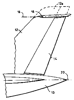
Figure 1 shows a side view of a fin and rudder arrangement in accordance with
the
invention shown partly broken away;
Figure 2 is a rear end view of the fin and rudder shown in Figure 1; and
Figure 3 is a plan view of the fin and rudder showing the delta shape of the
end plate.
A fuselage 10 carries a fin 12 at its rear end atid a rudder 14 is hinged to
the fin 12 in
known manner.

CA 02339208 2001-01-31
11-07-2000 90PCT GB 009902568
- 3 -
The upper end of the fin 12 carries a delta-shape end plate 16 which has a
dihedral
angle of r. The end plate 16 has a chord line 18 which is inclined at an angle
to a
horizontal datum 20 of the fuselage 10, for example by -2 degrees.
The upper end of the rudder 141ies closely adjacent the underside of the end
plate 16
and is preferably in sealing contact therewith. The selected dihedral angle 1-
ensures
that the upper end of the rudder remains in sealing contact with the end plate
when
being deflected about its inclined hinge iine. It will be noted from Figure 3
that an
angle D between leading edges of the end plate 16 is sufficient to ensure that
end
plates 16 will cover the rudder 14 at all rudder deflections as indicated by
broken lines
in Figure 3.
By using the fin construction shown, the fin and rudder lift curve slopes will
be
increased thereby enabling the fin and rudder to provide a lift curve slope
equivalent to
a larger fin 12a as indicated in broken lines in Figure 1, with minimum change
in
overall wetted area (i.e. the surface area exposed to the airflow).
Alternatively, the
size of the fin and rudder can be reduced to provide the same lift as
previously
achieved by a larger arrangement.
The use of the end plate 16 improves the longitudinal stability of the
aircraft and
aircraft stall characteristics are improved due to nose-down pitch from the
end plate
which will increase non-linearly with incidence.
AMENDED SHEET

CA 02339208 2001-01-31
11-07-2000 Isopcr GB 009902568
- 4 -
The end plate itself is highly stall resistant because the highly swept back
leading edge
generates a leading edge vortex flow which maintains lift on the end plate up
to high
angles of attack. In a pushover manoeuvre (i.e. when the joystick is pushed
forward)
which results in a negative angle of attack, the end plate will provide a
pitching
moment at an angle of attack greater than that for tailplane stall.
The effect of the end plate will also reduce the induced drag of the fin in
the engine out
condition and will also act as a lightning conductor and shield the rudder
from
lightning strikes which can damage components such as rudder actuators,
hydraulic
pipes and rudder hinges.
As the use of the end plate 16 effectively enables the height of the fin to be
reduced,
there will be a reduction in fin root bending moment for a given side force
compared
to that when using the taller fin 12a shown in broken lines.
AMENDED SHEET

Representative Drawing
A single figure which represents the drawing illustrating the invention.
Administrative Status

2024-08-01:As part of the Next Generation Patents (NGP) transition, the Canadian Patents Database (CPD) now contains a more detailed Event History, which replicates the Event Log of our new back-office solution.

Please note that "Inactive:" events refers to events no longer in use in our new back-office solution.

For a clearer understanding of the status of the application/patent presented on this page, the site Disclaimer , as well as the definitions for Patent , Event History , Maintenance Fee  and Payment History  should be consulted.

Event History

Description Date
Time Limit for Reversal Expired 2017-08-03
Letter Sent 2016-08-03
Letter Sent 2011-05-20
Grant by Issuance 2007-11-13
Inactive: Cover page published 2007-11-12
Inactive: Final fee received 2007-06-19
Pre-grant 2007-06-19
Notice of Allowance is Issued 2007-05-18
Letter Sent 2007-05-18
Notice of Allowance is Issued 2007-05-18
Inactive: Approved for allowance (AFA) 2007-04-25
Letter Sent 2007-03-14
Reinstatement Request Received 2007-01-30
Amendment Received - Voluntary Amendment 2007-01-30
Reinstatement Requirements Deemed Compliant for All Abandonment Reasons 2007-01-30
Inactive: Abandoned - No reply to s.30(2) Rules requisition 2007-01-17
Inactive: S.30(2) Rules - Examiner requisition 2006-07-17
Letter Sent 2004-04-15
Request for Examination Received 2004-03-22
Request for Examination Requirements Determined Compliant 2004-03-22
All Requirements for Examination Determined Compliant 2004-03-22
Letter Sent 2002-08-29
Letter Sent 2001-06-07
Inactive: Cover page published 2001-05-04
Inactive: Single transfer 2001-05-01
Inactive: First IPC assigned 2001-04-30
Inactive: Courtesy letter - Evidence 2001-04-10
Inactive: Notice - National entry - No RFE 2001-04-09
Application Received - PCT 2001-03-31
Application Published (Open to Public Inspection) 2000-02-17

Abandonment History

Abandonment Date Reason Reinstatement Date
2007-01-30

Maintenance Fee

The last payment was received on 2007-07-23

Note : If the full payment has not been received on or before the date indicated, a further fee may be required which may be one of the following

  • the reinstatement fee;
  • the late payment fee; or
  • additional fee to reverse deemed expiry.

Please refer to the CIPO Patent Fees web page to see all current fee amounts.

Owners on Record

Note: Records showing the ownership history in alphabetical order.

Current Owners on Record
AIRBUS OPERATIONS LIMITED
Past Owners on Record
LESLIE LEIGH HYDE
Past Owners that do not appear in the "Owners on Record" listing will appear in other documentation within the application.
Documents

To view selected files, please enter reCAPTCHA code :


To view images, click a link in the Document Description column. To download the documents, select one or more checkboxes in the first column and then click the "Download Selected in PDF format (Zip Archive)" or the "Download Selected as Single PDF" button.

List of published and non-published patent-specific documents on the CPD .

If you have any difficulty accessing content, you can call the Client Service Centre at 1-866-997-1936 or send them an e-mail at CIPO Client Service Centre.


Document
Description 
Date
(yyyy-mm-dd) 
Number of pages   Size of Image (KB) 
Representative drawing 2001-05-04 1 4
Abstract 2001-01-31 1 50
Description 2001-01-31 5 157
Claims 2001-01-31 2 48
Drawings 2001-01-31 1 17
Cover Page 2001-05-04 1 22
Description 2007-01-30 5 150
Claims 2007-01-30 2 45
Representative drawing 2007-10-16 1 6
Cover Page 2007-10-16 1 31
Reminder of maintenance fee due 2001-04-09 1 111
Notice of National Entry 2001-04-09 1 193
Courtesy - Certificate of registration (related document(s)) 2001-06-07 1 112
Reminder - Request for Examination 2004-04-06 1 116
Acknowledgement of Request for Examination 2004-04-15 1 176
Notice of Reinstatement 2007-03-14 1 171
Courtesy - Abandonment Letter (R30(2)) 2007-03-14 1 166
Commissioner's Notice - Application Found Allowable 2007-05-18 1 164
Maintenance Fee Notice 2016-09-14 1 178
Correspondence 2001-04-09 1 23
PCT 2001-01-31 15 498
Correspondence 2007-06-19 1 37