Note: Descriptions are shown in the official language in which they were submitted.
CA 02339236 2001-O1-31
WO 00/14674 PCT/US99/19313
1
METHOD OF CALIBRATION AND REAL-TIME
ANALYSIS OF PARTICULATES
FIELD AND BACKGROUND O~ THE INVENTION
The present invention relates to chemical analysis and, more particularly, to
on-line quantitative analysis of chemical species in particulates. In
particular, the
present invention relates to the on-line quantitation of polycyclic aromatic
hydrocarbons (PAH) and other fluorescent contaminants in aerosols.
PAH are among the many organic materials that are commonly encountered as
trace-level environmental contaminants in effluents associated with incomplete
combustion, pyrolysis and other thermal degradation processes. The PAH family,
defined as containing hydrocarbon species with three or more fused aromatic
rings,
includes many compounds suspected of being potent carcinogens. Therefore,
identification and determination of emission levels of PAH is important in
environmental assessment. Moreover, emission monitoring of PAH compounds is of
considerable industrial importance as well, since several industrial processes
can be
controlled by a fast feedback of PAH composition and concentration.
Several procedures, such as gas chromatography / mass spectrometry (GC-
MS), have been developed and applied for obtaining compound specific
information
for evaluation of PAH contamination. These procedures cannot be applied
directly to
particulate PAH analysis, because they all involve several sample preparation
steps in
which the particles are destroyed. The GC-MS methods, in particular, are
complicated and expensive; they require state of the art high vacuum equipment
and
extensive investment of expert analyst's time. It is not cost effective to
apply them
routinely to samples that may not, in fact contain any relevant levels of PAH.
Moreover, the GC-MS methods are not on-line methods for particulate analysis,
and
cannot be used for obtaining fast feedback which is required for both
environmental
protection and for industrial process control.
PAH compounds are produced primarily as a result of incomplete combustion
CA 02339236 2001-O1-31
WO 00/14674 PCTNS99/19313
2
of organic matter, and thus are believed to exist in both the vapor phase and
the solid
phase, as an integral constituent of particulate matter. Because the
concentration of
such pollutants in most atmospheric samples is very low, and because they are
often
associated with other contaminants, the identification and quantification of
PAH are
usually complex, time consuming and often inaccurate because of multistep
isolation
and determination techniques. This problem is primarily associated with
analysis of
PAH on aerosol particles, which is considered the most complicated task for
classical
methods of PAH analysis.
Nevertheless, analysis of PAH on aerosols is of intense interest to both
1o industry and governmental environmental protection bodies. It has been
proven that
most PAH mass is found onto aerosol particles, rather than in the vapor phase.
(This
is because of the low vapor pressure of many of these compounds at ambient
temperature.) The distribution of PAH as a function of aerodynamic diameter,
for
coke oven emission, shows that most contamination is associated with particles
of
diameter of 1-10 p,m. The absolute concentration of PAH compounds an air is
compound-dependent, and is usually in the range of 0.02-0.2p.g m'3. Absolute
concentration in the vicinity of industrial sites may be ten times higher, and
concentrations in the p,g m 3 and higher, of particles having diameters
between 10 and
100 p,m or more, have been measured close to combustion chimneys.
2o Most of the currently employed analytical methods for PAH on aerosols
involve (a) collection of particulate PAH by drawing a large volume of air
through a
filter, (b) extraction of the PAH collected on a filter paper with an organic
solvent, and
(c) chromatographic cleanup and separation followed by (d) identification and
quantitation using one or a combination of spectroscopic and chromatographic
methods, or mass spectrometry analysis in a high vacuum chamber.
There are a number of analytical difficulties associated with these
traditional
methods. The real-time analysis of PAH present in ambient air (fumes, coke
oven
emission, smoke or other gaseous media) cannot be achieved, mainly because of
lack
of selectivity, sensitivity, and mobility of the analytical instrumentation.
Considering
3o the above difficulties, and taking into account that traditional methods do
not provide
on-line and in-situ results, it follows that there is a widely recognized need
for, and it
would be highly advantageous to have, a method for real-time, on-line analysis
of
CA 02339236 2001-O1-31
WO 00/14674 PCT/US99/19313
3
aerosol particles for PAH.
~M IE~Y OF THE INVENTION
According to the present invention there is provided a method of analyzing
particles for a plurality of species, including the steps of (a) providing:
(l) a plurality
~of morphology types; (ii) a plurality of spectrum types; (iii) a plurality of
target
classes, each of the target classes corresponding to one of the morphology
types and
one of the spectrum types, and (iv) a relationship between a descriptor vector
and a
concentration vector, the descriptor vector including a plurality of elements,
each
1o element of the descriptor vector corresponding to a different one of the
target classes,
the concentration vector including a plurality of elements, each element of
the
concentration vector corresponding to a different one of the species; (b)
acquiring a
plurality of images of the particles, each of the images being acquired at a
different
wavelength; (c) inferring the descriptor vector from the plurality of images;
and (d)
using the relationship to infer the concentration vector from the descriptor
vector.
The present invention is a method of quantification of species on particles.
The species may be either chemical species, such as PAH, or biological
species,
particularly microorganisms such as bacteria and algae. In the latter case,
the
microorganism itself may be the particle.
For definiteness, the description below focuses on the use of the present
invention for the quantitation of PAH in aerosol particles. Therefore, in the
description below, the images are of fluorescent or phosphorescent light
emitted by
the particles, under excitation by incident ultraviolet light, rather than of
light
reflected or transmitted by. the particles. Nevertheless, the scope of the
present
invention includes the analysis of images of light reflected or transmitted by
the
particles, in addition to the analysis of light emitted by the particles in
response to
excitation. Furthermore, the excitation may be by incident electromagnetic
radiation
of any suitable wavelength, notably visible and infrared light, or even by
simply
heating the particles.
The particles to be analyzed are spread out on a two-dimensional surface, so
that each pixel in each two dimensional intensity image represents a part of
only one
particle. Generally, aerosol particles collected on the surface of a filter,
as in the prior
CA 02339236 2005-02-04
30048-3
4
art method of PAH analysis, are spread out appropriately. When the images are
of
light emitted by the particles in response to incident light, there are two
general
v rriethods of acquiring the images. In the first method, the surface to be
imaged is
irradiated homogeneously, and the emitted light is transferred, via a suitable
optical
s system, to a spectroscopic imaging device. Examples of such devices are 'the
acousto-optic tunable filter and the scanning interferometer described by
Le'wis et al.
in US Patent No. 5,377,003; the scanning interferometer described by Cabib et
al, in
US Patent No. 5,539,517 and produced by Applied Spectral Imaging, Ltd, of
Migdal
Haemek, Israel, under the name "ASI SD2000", and the Iiquid crystal tunable
filter
described in Fluorescence Imaging Spectroscopy and Microscopy {Xue Feng Wang
Brian Herman, editors, John Wiley & Sons, Tnc., 1996). In the second method,
the surface to be imaged is scanned using a focused beam of light, and the
emitted
light is analyzed by a conventional spectrometer. Under both methods, the
spectrally
decomposed emitted light is imaged by one of several methpds. The
straightforward
method uses a solid-state area image sensor array such as an array of charge
coupled
detectors (CCD), with each detector of the array acquiring one pixel of each
image.
.Another method is to acquire each image one row of pixels at a time using a
scanning diode array. CCD arrays recently have become available that are
sufficiently dense that several images con~esponding to several different
wavelengths
2o can be acquired simultaneously. For example, a 4096 x 4096 CCD array can
acquire
64 512 x 512 images simultaneously, at 64 different wavelengths. As an
alternative
to the spectrometers, these large CCD arrays can be used with a large number
{64 in
the example given) of narrow band optical filters to obtain single-wavelength
images. Under this alternative, the sample must be moved, for example on a
piezoelectric stage, from one filter to another. In the analysis of aerosol
particles for
PAH, the optical system includes a microscope, so that the final single-
wavelength
images are sufficiently magnified to resolve the target particles ax the
desired
resolution of one or more pixels per particle.
The output of the image acquisition is, for each imaged portion of the two-
3o dimensional surface, a set of images, each image at a different wavelength.
These
images are digitized and analyzed by standard image processing methods to
produce,
CA 02339236 2001-O1-31
WO 00/14674 PCT/US99/19313
for each imaged portion of the two-dimensional surface, spectral images of
targets.
Typically, each target corresponds to one particle, or, in the case of images
of PAH
fluorescence, the portion of the surface of the particle occupied by one PAH
species.
Each target is classified as belonging to one of a standard set of morphology
types and
5 one of a standard set of spectrum types. For each target, a value of an
extensive
property, such as area or total intensity, is obtained. These values are
summed
separately for each target class. The array of summed extensive properties
constitutes
a collective descriptor vector for all the targets. A relationship is provided
that relates
the descriptor vector to a vector of concentrations of species of interest. If
the species
to of interest are chemical species, then the concentrations are expressed as
mass per unit
area. If the species of interest are biological species, then the
concentrations are
expressed as number of organisms per unit area. This relationship is used to
infer the
concentrations of the species of interest from the descriptor vector.
The set of standard morphology types, the set of standard spectrum types, and
the relationship between descriptor vectors and concentration vectors are
obtained by
a calibration procedure. A set of calibration samples is provided. These
calibration
samples may be collections of particles of known composition or collections of
particles of unknown composition but of the type that is to be analyzed. For
each
calibration sample, one or more sets of images at different wavelengths are
acquired.
Each image includes a plurality of pixels. With each pixel is associated an
intensity
value. The set of intensity values of pixels that have a common location in
the images
of one set constitute a spectrum associated with that location. Spectra whose
summed
intensity exceeds a predetermined threshold are classified by cluster analysis
to obtain
the standard spectrum types. See, for example, R. L. Kettig and D. Landgrebe,
"Classification of multispectral image data by extraction and classification
of
homogeneous objects", IEEE Transactions on Geoscience Electronics, Vol. GE14
p.
19 (1976). Locations whose summed intensity exceeds the threshold are grouped
into
calibration targets. For each calibration target, values of morphological
parameters
such as area or aspect ratio is calculated. The values of the morphological
parameters
are classified by cluster analysis to obtain the standard morphology types.
Each
calibration target also is classified as belonging to one of the standard
spectrum types.
For each calibration target, a value of an extensive parameter is obtained,
and these
CA 02339236 2005-02-04
30048-3
6
values are summed to provide a calibration descriptor vector for each, as
described
above.
The calibration samples now are analyzed by a prior art method, if necessary,
to obtain, for each calibration sample, a calibration concentration vector,
each
element of which is a value of the concentration of a species of interest in
the
calibration sample. The desired relationship between the calibration
descriptor
vectors and the calibration concentration vectors now is determined by
standard
computational methods, for example multivariate analysis or by training a
neural net.
The output of multivariate analysis is a linear transformation, expressed as a
matrix,
1o that relates descriptor vectors to corresponding concentration vectors. The
descriptor vector is multiplied by this matrix to yield the concentration
vector. The
output of the training of a neural net is a trained neural net whose inputs
are
descriptor vectors and whose outputs are corresponding concentration vectors.
With regard to analysis of chemical species, the present invention is similar
to the method of particulate analysis described in the same Applicant's PCT
application, WO 98/33058 AI. The significant differences between the present
invention and WO 98/33058 A1 are as follows:
1. In WO 98/33058 Al, the spectra in the database are spectra of pure
chemical species. In the present invention, the standard spectra are
determined
2o empirically in the calibration procedure. This is important in the case of
PAH
adsorbed on aerosols, because the spectra of adsorbed chemical species in
general
and of PAH in particular are known to be altered by the surfaces on which they
are
adsorbed and by contaminants.
2. In WO 98/33058 A1, the shapes of the particles are considered along
with the spectra of the particles, but only in an ad hoc manner. In the
present
invention, the relationship between the descriptor vector and the
concentration
vector accounts explicitly and simultaneously for both morphologies and
empirically
determined spectra. This is particularly important in the case of PAH adsorbed
on
aerosols, because the fluorescence spectra of PAH crystals are known to depend
on
3o crystal morphology in general and crystal size in particular.
CA 02339236 2001-O1-31
WO 00/14674 PCTNS99/19313
7
BRTEF DESCRIPTION OF THE DRAWINGS
The invention is herein described, by way of example only, with reference to
the accompanying drawings, wherein:
FIG. 1 is a schematic diagram of a system for quantifying PAH in aerosols;
FIG. 2 is a flow diagram of the detection and quantification of PAH;
FIG. 3 is a flow diagram of the calibration of the quantification method
FIGS. 4A and 4B are fluorescence spectra of algal species.
DESCRIPTION OF THE PREFERREID EMBODIMENTS
1 o The present invention is of a method of quantitative analysis of chemical
species in particulates which is based on an empirically determined
relationship
among spectra, morphologies and concentrations. Specifically, the present
invention
can be used for real-time, on-line quantification of PAH in aerosols.
The principles and operation of particulate analysis according to the present
invention may be better understood with reference to the drawings and the
accompanying description.
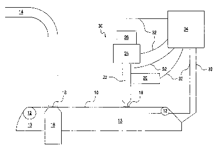
Referring now to the drawings, Figure 1 is a schematic diagram of an
automatic on-line real-time system for monitoring PAH in aerosols. A roll of a
non-
fluorescing substrate 10 such as non-fluorescing filter paper is mounted on a
pair of
2o rollers 12, which move substrate 10 from left to right as seen in Figure 1.
A high
volume air pump 16 sucks in contaminated air via a pipe 14 and through
substrate 10,
depositing aerosol particles 18 on substrate 10. Optionally, a filtration
system (not
shown), .such as a l OPM high volume particle sampler, may be placed in pipe
14 to
select particles below a certain size, for example, 10~. Rollers 12 move
aerosol
particles 18 to a position for viewing under a spectroscopic imaging system 30
that
includes a source of ultraviolet light 20, an optical system 22, a
spectroscopic imaging
device 24 and CCD camera 26 having a suitable sensitivity and dynamic range.
Typical spectroscopic imaging systems are described, for example, in the Lewis
et al.
patent cited above, and will not be elaborated fiwther herein.
Components 20, 22, 24 and 26 of spectroscopic imaging system 30 are
connected by suitable control/data links 32 to a control system 34. Light
source 20
illuminates particles 18 homogeneously via optical system 22, as shown in
Figures 6
CA 02339236 2001-O1-31
WO 00/14674
8
PCTNS99/19313
and 8 of the Lewis et al. patent cited above. In other embodiments of the
present
invention, light source 22 directs ultraviolet light directly onto particles
18, without
the intervention of optical system 22. Rollers 12 also are connected by a
control/data
link 32 to control system 34 so that substrate 10 can be advanced under the
control of
control system 34. Rollers 12 are mounted on a stage 13 which has two degrees
of
freedom of motion: laterally (into and out of the plane of Figure 1 ) and
vertically.
The vertical motion of stage 13 is used to effect autofocusing. Stage 13 also
is
controlled by control system 34 via a controUdata link 32. The combined
motions of
rollers 12 and stage 13 allow substrate 10 to be moved laterally in three
directions
1o under optical system 22.
Control system 34 is based on a personal computer, and includes a frame
grabber, for acquiring images from camera 26, as well as other hardware
interface
boards for controlling rollers 12, stage 13 and the other components 20, 22
and 24 of
spectroscopic imaging system 30. The software of control system 34 includes a
database of empirically determined morphology types and spectrum type and code
for
implementing the image processing and quantification algorithms described
below.
Preferably, rollers 12 are used to move substrate 10 to the right, as seen in
Figure 1, in a stepwise fashion, so that while control system 34 is acquiring
and
analyzing images of one sample of particles 18, pump 16 is collecting the next
sample
of particles 18. Rollers 12 and stage 13 also are used to move particles 18 a
much
shorter distance laterally under optical system 22, to allow control system 34
to
acquire images from several fields of view in a sample.
Figure 2 is a flow diagram of the process of automatic detection and
quantification of PAH. By shifting the field of view laterally, using rollers
12 and
stage 13, images of all fields of view of the sample are acquired (blocks 40
and S6).
Within each field of view, a set of images are acquired at the desired
wavelengths
(block 44) and the single-wavelength images are summed to give a summed, or
gray
level, image (block 46). Note that there is a one to one correspondence
between the
pixels of the summed image and what is referred to herein as the "common
locations"
of pixels of the single-wavelength images.
Subsequent image processing analyzes the images in terms of targets. Each
target is a collection of pixels of single-wavelength images whose summed-
image
CA 02339236 2001-O1-31
WO 00/14674 PCT/US99/19313
9
pixels have: (a) intensities above a preset threshold and (b) adjoining
locations. The
targets are identified (block 50) and classified (block 52), and each target
is assigned a
value of an extensive property (block 54).
The morphology types in the database are empirically determined ranges of
parameters used to characterize the morphologies of the targets. For example,
a set of
targets could be described in terms of areas and aspect ratios, with three
area ranges:
<5 square microns (small)
5 - 50 square microns (medium)
>5O square microns (large)
1o and two aspect ratio ranges:
1 to 1.5 (round)
>1.5 (elongated).
The cross-product of these ranges gives six morphology types: small round,
small
elongated, medium round, medium elongated, large round and large elongated.
Raw
morphology types may be merged to fewer types. For example, if the aspect
ratios of
small and large particles are of no consequence, the six raw morphology types
may be
merged to four: small ("sm"), medium round ("mr"), medium elongated ("me"),
and
large ("lg").
The spectrum types in the database are empirically determined normalized
discrete functions of wavelength. Suppose that the single-wavelength images
are
acquired at L discrete wavelengths ~,1. Then each standard spectrum S is a
collection
of non-negative numbers s1, one per wavelength, normalized as
L
~sr =1 (1)
r=i
The target classes are direct products of the morphology types and the
spectrum types. For example, if there are four morphology types (sm, mr, me
and 1g)
and three spectrum types (SA, SB and S~) then there are twelve target classes.
There are two preferred methods for identifying targets (block 50) and
classifying targets (block 52). The first method takes into account the
spectra of the
single-wavelength images, i.e., the intensities of the pixels at common
locations.
3o Suppose that at one location, the L pixels have intensities p1. Each
location whose
summed intensity exceeds the threshold is classified by spectrum type, by
seeking the
CA 02339236 2001-O1-31
WO 00/14674 PCT/US99/19313
spectrum type that most closely matches the location spectrum. One way of
doing
this matching is to take the dot product of the location spectrum with each of
the
L
spectrum types: ~ p,s; , where a indexes the spectrum type. The location is
,_,
assigned the spectrum type whose dot product with the location spectrum is
largest.
5 Another way of doing this matching is to normalize the intensities pJ to
one, as in
equation (1), and then to compute the squared Euclidean distance between the
location
spectrum and each of the spectrum types: ~(p, - p -s; +s")Z , where p is the
~_.
mean of the p~ and s" is the mean of the s°'l for each a. The location
is assigned the
spectrum type whose Euclidean distance from the location spectrum is smallest.
10 Then, all adjoining locations of identical spectrum type are grouped
together as
targets.
The values of the parameters that define target morphology are computed by
standard methods. For example, the area of a target is determined simply by
counting
the number of locations in the target; and the aspect ratio of a target is
determined by
finding the distance (length) between the two locations of the target that are
farthest
from each other, finding the maximum width of the target in the direction
perpendicular to a line connecting those two pixels, and dividing the length
by the
width. Each target is assigned to the target class that corresponds to the
values of the
morphology parameters and the spectrum type that was used to define the
target.
2o The second preferred method of identifying and classifying targets forms
the
targets by grouping together locations whose summed intensities exceed the
threshold,
without regard to location spectra. Then, within each target, each location's
spectrum
is classified by spectrum type as above, and a single representative spectrum
type for
the entire target is selected from among the matching spectrum types. The
simplest
way to select the representative spectrum type is by plurality: the spectrum
type that is
matched to the largest number of locations within the target is chosen as the
representative spectrum type. The target morphology type is determined as in
the first
method, and the target is assigned to the target class that corresponds to the
values of
the morphology parameters and the representative spectrum type. Each target
now is
assigned a value of an extensive property such as target area or total target
intensity
CA 02339236 2005-02-04
30048-3
11
(block 54):
After all fields of view have been processed (block 56); a descriptor vector d
is
formed (block 58) by summing the values of the extensive p roperiy o f t he
targets o f
each class. The vector d has as many elements as there are target classes, and
the
elements of the vector d are the sums of the extensive property values of the
targets of
the corresponding target class: The last step (block 60) is to turn the
descriptor vector
into a concentration vector c whose elements are the concentrations, in mass
per unit
area, of the PAH species of interest. This is done using a relationship,
determined by
the calibration procedure described below, between the vectors d and c. If
this
relationship is determined by multivariate analysis, then the relationship is
embodied in
a matrix M such that c = dlts. If this relationship is determined by training
a neural net,
then d is provided to the trained neural net as input, and c is the resulting
output.
Another noteworthy difference between the present invenrion and the method of
particulate analysis described in the same Applicant°s PCT application,
WO 98/33058
A1, is that in the later patent application, only fields of view in which at
least one target
appears are considered. In the present invention, all fields of view are
considered, in
order to obtain correct statistics regarding the measured extensive property
values.
The process of Figure 2 is calibrated using a set of N calibration samples; of
the
kind of particles that are to be analyzed. The calibration samples may ,be
artificial
samples of known composition or representative collections of particles, such
as
particles 18, that are to be analyzed> Figure 3 is a flow diagram of the
calibration
procedure. The calibration procedure includes two loops over the N calibration
samples. In the first loop, single-wavelength images of fields of view of the
samples are
acquired. Between the two loops, the database spectrum types and the database
morphology types are determined. In the second loop, the relationship between
descriptor vectors and concentration vectors is determined.
In the first loop (block 70), single-wavelength . images of a 11 fields o f v
iew o f
each sample are acquired as described above (blocks 40, 42, 44, 46 and 5~.
Images that
include fluorescing particles are saved for subsequent processing (block 72).
After all
3o the relevant single-wavelength images of all the samples have been
collected (block 74),
the spectra of locations whose summed intensity exceeds the threshold are
classified by
cluster analysis to obtain the database spectrum types (block 76).
CA 02339236 2005-02-04
3.0048-3
i~
Targets are identified as described above, the values of the morphology
parameters of
each target are computed, and the database morphology types are abtained by
applying
cluster analysis to the resulting set of morphology parameter values (block
78). The
database m orphology and spectrum types are used to define target classes, and
the
targets in all t he fields o f v iew o f a 11 t he s amples a re c lassified a
ccording t o t hese
classes (block 80). Each target is assigned a value of an extensive property
(block
82). Tf the calibration samples are artificial, then the concentrations of the
PAH
species of interest are known. If the calibration samples are representative
collections,
then, at the end of the first loop, each calibration sample is analyzed by a
prior art
(e.g.; w et c hemistry) t echnique t o d etermine t he c oncentrations t
herein o f t he PAH
species of interest (block 84).
In the second loop over samples (block 86), for each sample, a calibration
descriptor vector r1" is formed (block 88) by summing the values of the
extensive
property of the targets of each class. (n E [ 1,N] is the index of the
sample.) A
calibration concentration vector cn is formed from the concentrations of the
PAH
species in the sample (block 90). After calibration descriptor vectors and
calibration
concentration vectors have been determined for all N calibration samples
('block 92), a
collective relationship between the descriptor vectors and the calibration
vectors is
determined (block 94). As noted above, under multivariate analysis this
relationship
is expressed as the matrix M that comes closest to giving c" = d"M for all N
samples.
The simplest way to obtain M is by unweighted linear least squares. Form a
matrix C
whose rows are the vectors c". Form a matrix D whose rows are the vectors d".
The
desired matrix M should come close to satisfying the equation
C = DM (2)
~ The unweighted linear least squares solution of equation (2) for M is the
generalized
inverse solution for M. Multiplying both sides by the transpose of D, DT gives
DTC = DTDM (3)
The right hand side of equation (3) now is a product of M with a square matrix
DTD.
Left-multiplying both sides of equation (3) by (DTD)'1 gives
M= {DTD)'1DTC (4)
Other, more sophisticated methods of approximating M within the scope of
multivariate analysis include principal component regression and partial least
squares.
CA 02339236 2001-O1-31
WO 00/14674 PCT/US99/19313
13
See, for example, H. Martens and T. Naes, Multivariate Calibration (John Wiley
&
Sons, 1989).
Alternatively, a neural network is trained, using the calibration descriptor
vectors and calibration concentration vectors as a training set. The desired
relationship between descriptor vectors and concentration vectors then is the
trained
neural network. See, for example, P. Yu. V. Anastassopoulos and A. N.
Venetsanopoulos, "Pattern classification and recognition based on morphology
and
neural networks", Can. J. Elect. and Comp. Eng., Vol. 17 No. 2 (1992) pp. 58-
59 and
the references therein.
As noted above, the scope of the present invention includes quantitation of
both chemical species and biological species. The procedure described above
for
analysis of PAH on aerosol particles applies, mutatis mutandis, to analysis of
airborne
microorganisms. Such analysis is important in the control of indoor air
pollution in
environments, such as airports, with closed air circulation systems.
Figure 4A shows the experimentally determined fluorescence spectrum, in
arbitrary intensity units, of an algal species collected as airborne
particulates. Figure
4B shows the experimentally determined fluorescence spectrum, also in
arbitrary
intensity units, of another algal species, also collected as airborne
particulates. The
spectrum of Figure 4B has two peaks, at about S20 nm and about 675 nm,
2o corresponding to juvenile and mature members of the species. Such spectra
can be
used for the classification of airborne microorganisms in the same way that
chemical
fluorescence spectra can be used to classify chemical species on aerosol
particles.
While the invention has been described with respect to a limited number of
embodiments, it will be appreciated that many variations, modifications and
other
applications of the invention may be made.