Language selection

Search

Patent 2339684 Summary

Third-party information liability

Some of the information on this Web page has been provided by external sources. The Government of Canada is not responsible for the accuracy, reliability or currency of the information supplied by external sources. Users wishing to rely upon this information should consult directly with the source of the information. Content provided by external sources is not subject to official languages, privacy and accessibility requirements.

Claims and Abstract availability

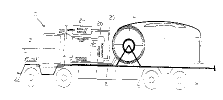
Any discrepancies in the text and image of the Claims and Abstract are due to differing posting times. Text of the Claims and Abstract are posted:

  • At the time the application is open to public inspection;
  • At the time of issue of the patent (grant).
(12) Patent Application: (11) CA 2339684
(54) English Title: DOWNHOLE JET PUMP
(54) French Title: POMPE A JET POUR FOND DE PUITS
Status: Deemed Abandoned and Beyond the Period of Reinstatement - Pending Response to Notice of Disregarded Communication
Bibliographic Data
(51) International Patent Classification (IPC):
  • F04F 3/00 (2006.01)
  • E21B 17/20 (2006.01)
  • E21B 37/00 (2006.01)
  • E21B 43/12 (2006.01)
  • F04F 5/24 (2006.01)
(72) Inventors :
  • ERICK, LEONARD LARRY (Canada)
(73) Owners :
  • COIL-TECH SERVICES LTD.
(71) Applicants :
  • COIL-TECH SERVICES LTD. (Canada)
(74) Agent: THOMPSON LAMBERT LLP
(74) Associate agent:
(45) Issued:
(22) Filed Date: 2001-03-02
(41) Open to Public Inspection: 2001-06-05
Examination requested: 2003-02-28
Availability of licence: N/A
Dedicated to the Public: N/A
(25) Language of filing: English

Patent Cooperation Treaty (PCT): No

(30) Application Priority Data: None

Abstracts

English Abstract


A wellsite pumping system, comprising a gas processing system including a
source of
compressed gas, the source of compressed gas having a low pressure inlet and a
high
pressure outlet, coil tubing connected to the high pressure outlet of the gas
processing
system, the coil tubing including a first tubing string connected to the high
pressure outlet
and a second tubing string running parallel to the first tubing string and
having an opening
for entry of fluid at a remote end from the high pressure outlet; and a
venturi connecting
the second tubing string to the first tubing string such that, in operation,
passage of gas
through the venturi from the first tubing string draws production fluid into
the second
tubing string. Preferably, the second tubing string is suspended within the
first tubing
string. The venturi may be formed by a horizontal passageway communicating
with a
vertical passageway with a restriction.


Claims

Note: Claims are shown in the official language in which they were submitted.

We claim:
1. A wellsite pumping system, comprising:
a gas processing system including a source of compressed gas, the source of
compressed gas having a low pressure inlet and a high pressure outlet;
coil tubing connected to the high pressure outlet of the gas processing
system, the
coil tubing including a first tubing string connected to the high pressure
outlet and a
second tubing string running parallel to the first tubing string and having an
opening for
entry of fluid at a remote end from the high pressure outlet; and
a venturi connecting the second tubing string to the first tubing string such
that, in
operation, passage of gas through the venturi from the first tubing string
draws production
fluid into the second tubing string.
2. The wellsite pumping system of claim 1 further comprising:
an internal combustion engine;
the gas processing system being connected to receive low pressure exhaust gas
from the internal combustion engine; and
a pump being provided within the gas processing system, the pump having a low
pressure inlet for receiving exhaust gases and the pump having a high pressure
outlet.
3. The wellsite pumping system of claim 2 in which the pump is a compressor
and
the gas processing system comprises an exhaust cooler.
4. The wellsite pumping system of claim 2 in which the pump is a compressor
and
the gas processing system comprises an exhaust separator.
5. The wellsite pumping system of claim 2 in which the pump is a compressor
and
the gas processing system comprises a particulate filter.
6

6. The wellsite pumping system claim 2 in which the gas processing system
comprises a particulate filter, exhaust cooler and exhaust separator in
series, followed by
a compressor.
7. The wellsite pumping system of claim 2 in which the pump is a compressor
and
the gas processing system comprises a particulate filter followed by an
exhaust cooler
and exhaust separator.
8. The wellsite pumping system of claim 7 in which the exhaust cooler is
followed by
the exhaust separator.
9. The wellsite pumping system of claim 1 in which the first tubing string is
disposed
within the second tubing string.
7

Description

Note: Descriptions are shown in the official language in which they were submitted.


CA 02339684 2001-03-02
TITLE OF THE INVENTION
Downhole Jet Pump
BACKGROUND OF THE INVENTION
Ol This invention relates to equipment used for producing wells.
02 Oil and gas wells have been produced by a jet pump in which inner and outer
strings of tubing are connected downhole using a venturi, and liquid flow
through the
outer tubing string then through the venturi into the inner tubing string
draws production
fluid into the inner tubing through an opening into the inner tubing. This
process has been
found to work, but requires a suitable liquid.
03 Cleaning out wells conventionally with a coiled tubing unit is accomplished
by
forcing compressed air/gas down the coiled tubing to the bottom of the well
and returning
the fluid/fill up the annulus between the coiled tubing and the wells original
production
casing. The fluids are earned up the annulus in slugs causing a pressure build-
up in the
lower portion of the well. This pressure build up may force fluids, fill, and
air back into
the producing zone, which may cause formation damage. Wells with production
casing
larger than four and one half inch are difficult to clean out due to reduced
annular velocity
of the compressed air. To clean a well out in this manner, the casing gas is
vented to
atmosphere through the entire job. This is expensive and not environmentally
friendly.
This invention is directed to providing an improved pumping system.
SUMMARY OF THE INVENTION
04 There is therefore provided in accordance with the invention a wellsite
pumping
system, comprising a gas processing system including a source of compressed
gas, the
source of compressed gas having a low pressure inlet and a high pressure
outlet, coil
tubing connected to the high pressure outlet of the gas processing system, the
coil tubing

CA 02339684 2001-03-02
including a first tubing string connected to the high pressure outlet and a
second tubing
string running parallel to the first tubing string and having an opening for
entry of fluid at
a remote end from the high pressure outlet; and a venturi connecting the
second tubing
string to the first tubing string such that, in operation, passage of gas
through the venturi
from the first tubing string draws production fluid into the second tubing
string.
Preferably, the second tubing string is suspended within the first tubing
string. The venturi
may be formed by a horizontal passageway communicating with a vertical
passageway
with a restriction.
OS In one aspect of the invention, the source of compressed gas forms part of
a
wellsite inert gas inj ector. The inert gas inj ector comprises an internal
combustion engine,
a gas processing system connected to receive low pressure; exhaust gas from
the internal
combustion engine, a pump within the gas processing system, the pump having a
low
pressure inlet for receiving exhaust gases and the pump having a high pressure
outlet; and
coil tubing connected to the high pressure outlet of the gas processing
system. The gas
processing system preferably comprises one or more of a particulate filter,
exhaust cooler
and exhaust separator in series, and in that order before the pump. The pump
may be a
compressor.
BRIEF DESCRIPTION OF THE DRAWINGS
06 There will now be described preferred embodiments of the invention with
reference to the drawings by way of illustration, and without intending to
limit the
generality of the claims, in which:
Fig. 1 is a schematic showing an embodiment of a source of compressed gas for
use with an embodiment of the invention; and
Fig. 2 is a schematic showing a down hole jet pump for use with an embodiment
of
the invention.
2

CA 02339684 2001-03-02
DETAILED DESCRIPTION OF PREFERRED EMBODIMENTS
07 In this patent document, "comprising" is used in its inclusive sense, and
does not
exclude other elements being present in the invention to which a claim refers.
Use of the
indefinite article "a" before an element of a claim means that at least one of
the elements is
present.
08 A wellsite inert gas injector 10 is preferably truck mounted as shown in
the figure
and utilizes exhaust from the truck's internal combustion engine 12 as source
of inert gas.
Preferably, the engine is a diesel engine. The exhaust is provided to coil
tubing 14, which
is mounted on the truck deck 16 in conventional manner. A conventional
connection (not
shown) is used to connect the outlet 18 to the coil tubing 14. Between the
engine 12 and
coil tubing 18 is a gas processing system 20 that is connected to receive low
pressure
exhaust gas from the internal combustion engine and provide high pressure
inert gas to the
coil tubing 14 through outlet 18. Low pressure and high pressure are relative
terms. What
matters is that gas at the high pressure outlet 18 has sufficient pressure for
use down a
well.
09 The gas processing system 20 incorporates several modules to process the
gas to
make it suitable for downhole use. The modules are connected in series by
conventional
gas tight couplings. First, on the exhaust outlet of the engine 12, is a
catalytic diesel
particulate filter 22, which may be one manufactured by Nett Technologies Inc.
Details of
the Nett diesel filter are available from Nett, and briefly described in the
following. The
Nett diesel filter 22 utilizes cordierite wall-flow monoliths to trap the soot
produced by
heavy-duty diesel engines. A cylindrical filter element in the filter 22 has
of many square
parallel channels running in the axial direction, separated by thin porous
walls. The
channels are open at one end, but plugged at the other. Particulate laden
exhaust gases are
forced to flow through the porous walls. Gas is able to escape through the
pares in the wall
material. Particulates, however, are too large to escape and are trapped in
the filter walls.
A proprietary noble metal catalyst is coated onto the inside surface of the
filter monolith.
The catalyst lowers the soot combustion temperature to allow the filter to
regenerate. The
3

CA 02339684 2001-03-02
accumulated soot is oxidized in the filter during regular operation of the
engine. Periods
with exhaust temperatures of at least 350 - 400 degrees Fahrenheit are
necessary for
proper filter regeneration. However, so far as this invention is concerned in
its broadest
preferred aspect, a particulate filter is required to sufficiently clean the
exhaust that the
gas processing components are not damaged and the remaining particulate in the
inert gas
does not have a negative effect on the well.
Following the filter 22 is an exhaust cooler 24, for example a fin type fan
driven
cooler, or other suitable cooler to reduce the temperature of the gases to a
temperature
suitable for compression, as for example cooling the exhaust gases from about
500 degrees
to 90 degrees Fahrenheit. Following the cooler 24 is a conventional liquid/gas
separator 26
for removing any liquid droplets that condense out of the exhaust when it is
cooled. It may
be either free standing or built into the exhaust cooler. Following the
separator 26 is a
compressor 28 or other suitable pump with a low pressure inlet 30 and a high
pressure
outlet 18. The compressor 28 should compress the exhaust gas to a sufficient
pressure for
cleaning a well, or such other application that the invention might be used
for.
11 The inert gas generator so described is mobile and may be taken from well
site to
well site. At the well site, the engine supplies nitrogen rich, essentially
oxygen free, but
contaminated inert gas for use in well clean out operations. The gas
processing system
cleans the gas for use downhole.
12 With an efficient internal combustion engine, it is expected that the
resulting
exhaust will be essentially oxygen free, with any remaining free oxygen
captured by
carbon monoxide to form carbon dioxide. Incorporation of other inert gases
from the
atmosphere besides nitrogen is acceptable. The water separator should separate
out water
droplets to avoid damage to the compressor, but need not render the exhaust
stream free of
water vapor. The exhaust stream may be 100% water saturated. The maximum
preferred
inlet temperature to the compressor is 10°F above ambient. A preferred
compressor is a
Hurricane Compressor capable of pumping at 330 cubic feet per minute at 2000
psi.
4

CA 02339684 2001-03-02
13 The coil tubing 14 is formed of two strings of endless tubing running in
the well
simultaneously (one inside the other). Fig. 2 shows the inner tubing 40 and
outer tubing 42
with an annulus 44 between them. The inner tubing 40 extends below the outer
tubing 42
and has an opening 46 for the flow of downhole fluid, for example production
hydrocarbons, into the inner tubing 40. A venturi 48 is provided with an inlet
50
communicating with the annulus 44 and an outlet 52 communicating with the bore
of the
inner tubing 40. The venturi 48 may be formed by a horizontal passageway 54
communicating with a vertical passageway 56 having a restriction 58 at the
outlet 52
where the flow through the venturi enters the inner tubing 40. Exhaust is
pumped down
the annulus 44 between the two strings 40, 42, through the venturi 48 and
lifts well fluids
up the inside string 40. Such a system may be used to produce oil wells.
14 By using a jet pump, the well need not be vented to atmosphere and would
have to
be taken off production to be cleaned out. Such jet pumps are known in the art
in
themselves, but the use of the exhaust system described would provide lower
installation
costs, quicker start up, less harm from sand to the pump and ready variation
of production
volumes from the well. This application is filed simultaneously with an
application
claiming the inert gas generator.
15 Immaterial modifications may be made to the invention described here
without
departing from the essence of the invention.

Representative Drawing
A single figure which represents the drawing illustrating the invention.
Administrative Status

2024-08-01:As part of the Next Generation Patents (NGP) transition, the Canadian Patents Database (CPD) now contains a more detailed Event History, which replicates the Event Log of our new back-office solution.

Please note that "Inactive:" events refers to events no longer in use in our new back-office solution.

For a clearer understanding of the status of the application/patent presented on this page, the site Disclaimer , as well as the definitions for Patent , Event History , Maintenance Fee  and Payment History  should be consulted.

Event History

Description Date
Application Not Reinstated by Deadline 2007-03-02
Time Limit for Reversal Expired 2007-03-02
Inactive: Abandoned - No reply to s.30(2) Rules requisition 2006-07-31
Inactive: IPC from MCD 2006-03-12
Deemed Abandoned - Failure to Respond to Maintenance Fee Notice 2006-03-02
Inactive: S.30(2) Rules - Examiner requisition 2006-01-30
Amendment Received - Voluntary Amendment 2005-11-17
Inactive: S.30(2) Rules - Examiner requisition 2005-09-14
Amendment Received - Voluntary Amendment 2005-07-20
Inactive: S.30(2) Rules - Examiner requisition 2005-01-20
Letter Sent 2004-10-07
Reinstatement Requirements Deemed Compliant for All Abandonment Reasons 2004-09-24
Deemed Abandoned - Failure to Respond to Maintenance Fee Notice 2004-03-02
Letter Sent 2003-03-28
Request for Examination Requirements Determined Compliant 2003-02-28
All Requirements for Examination Determined Compliant 2003-02-28
Request for Examination Received 2003-02-28
Inactive: Cover page published 2001-06-06
Application Published (Open to Public Inspection) 2001-06-05
Inactive: First IPC assigned 2001-05-24
Letter Sent 2001-05-18
Inactive: First IPC assigned 2001-05-01
Inactive: IPC assigned 2001-05-01
Inactive: Single transfer 2001-04-18
Inactive: Courtesy letter - Evidence 2001-04-10
Inactive: Filing certificate - No RFE (English) 2001-04-05
Filing Requirements Determined Compliant 2001-04-05
Application Received - Regular National 2001-04-05

Abandonment History

Abandonment Date Reason Reinstatement Date
2006-03-02
2004-03-02

Maintenance Fee

The last payment was received on 2005-01-14

Note : If the full payment has not been received on or before the date indicated, a further fee may be required which may be one of the following

  • the reinstatement fee;
  • the late payment fee; or
  • additional fee to reverse deemed expiry.

Please refer to the CIPO Patent Fees web page to see all current fee amounts.

Fee History

Fee Type Anniversary Year Due Date Paid Date
Application fee - small 2001-03-02
Registration of a document 2001-04-18
MF (application, 2nd anniv.) - small 02 2003-03-03 2003-02-28
Request for examination - small 2003-02-28
MF (application, 3rd anniv.) - small 03 2004-03-02 2004-09-24
Reinstatement 2004-09-24
MF (application, 4th anniv.) - small 04 2005-03-02 2005-01-14
Owners on Record

Note: Records showing the ownership history in alphabetical order.

Current Owners on Record
COIL-TECH SERVICES LTD.
Past Owners on Record
LEONARD LARRY ERICK
Past Owners that do not appear in the "Owners on Record" listing will appear in other documentation within the application.
Documents

To view selected files, please enter reCAPTCHA code :


To view images, click a link in the Document Description column. To download the documents, select one or more checkboxes in the first column and then click the "Download Selected in PDF format (Zip Archive)" or the "Download Selected as Single PDF" button.

List of published and non-published patent-specific documents on the CPD .

If you have any difficulty accessing content, you can call the Client Service Centre at 1-866-997-1936 or send them an e-mail at CIPO Client Service Centre.


Document
Description 
Date
(yyyy-mm-dd) 
Number of pages   Size of Image (KB) 
Representative drawing 2001-06-06 1 10
Abstract 2001-03-02 1 24
Description 2001-03-02 5 231
Claims 2001-03-02 2 55
Drawings 2001-03-02 2 30
Cover Page 2001-06-06 1 38
Description 2005-07-20 5 225
Claims 2005-07-20 3 103
Description 2005-11-17 5 218
Courtesy - Certificate of registration (related document(s)) 2001-05-18 1 113
Filing Certificate (English) 2001-04-05 1 164
Reminder of maintenance fee due 2002-11-05 1 109
Acknowledgement of Request for Examination 2003-03-28 1 185
Courtesy - Abandonment Letter (Maintenance Fee) 2004-04-27 1 175
Notice of Reinstatement 2004-10-07 1 166
Courtesy - Abandonment Letter (Maintenance Fee) 2006-04-27 1 177
Courtesy - Abandonment Letter (R30(2)) 2006-10-10 1 167
Correspondence 2001-04-05 1 25
Fees 2003-02-28 1 33
Fees 2004-09-24 1 31
Fees 2005-01-14 1 27