Note: Descriptions are shown in the official language in which they were submitted.
CA 02340006 2001-02-08
WO 00/09198 PCTNS98/16643
PERCUTANEOUS OXYGENATOR FOR INDUCING A
RETROGRADE PERFUSION OF OXYGENATED BLOOD
1. Field of the Invi~ ntion. The present invention relates
generally to the field of percutaneous oxygenators. More specifically,
the present invention discloses a system for inducing a retrograde
flow of oxygenated blood to a compromised organ within the body.
2. Statement of the Problem. It has been recognized for
centuries that oxygenated blood is transported from the heart through
arteries of progressively diminishing size ending in arterial capillaries
that provide oxygen to the tissues that make up various organs.
Blood that has been depleted of oxygen in these organs then gathers
in venous capillaries and is carried back to the heart through a
progressively enlarging venous system, ending in the superior and
inferior vena cava, which deliver venous blood (which is low in oxygen
content and high in carbon dioxide content) to the right atrium of the
heart. At the capillary level, the arterial and venous capillaries
interconnect so that blood flow which is normally antegrade from the
arterial to the venous side, can potentially flow retrograde from the
venous to the arterial side. The ability to nourish organs by providing
oxygenated blood in a retrograde fashion has been used to provide
retrograde perfusion to both the heart and the brain during complex
surgical procedures on the heart and the great vessels (i.e.,
CA 02340006 2001-02-08
WO 00/09198 PGT/US98/16643
-2-
ascending aorta). However, this requires the use of complicated
externally-situated pumps and oxygenators.
A variety of percutaneous oxygenators and systems for
inducing retrograde fluid flow for other purposes have been used in
the past, including the following:
Inventor latent No. Issue Date
Stevens et al. 5,584,803 Dec. 17, 1996
Boyd et al. 5,558,644 Sep. 24, 1996
Hattler et al. 5,501,663 Mar. 26, 1996
Brown et al. 5,466,216 Nov. 14, 1995
Machold et al. 5,458,574 Oct. 17, 1995
Yock 5,451,207 Sep. 19, 1995
Hattler 5,376,069 Dec. 27, 1994
Hattler 5,219,326 June 15, 1993
Hattler 5,207,640 May 4, 1993
Hattler 5,122,113 June 16, 1992
Hattler 4,911,689 Mar. 27, 1990
Hattler 4,986,809 Jan. 22, 1991
Calderon 4,883,459 Nov. 28, 1989
U.S. Patent Nos. 5,584,803 (Stevens et al.), 5,458,574
(Machold et al.), and 5,558,644 (Boyd et al.) are a family of patents
relating to the same general invention. The heart muscle is paralyzed
by the antegrade or retrograde delivery of a cardiopfegic fluid through
the patient's coronary arteries or coronary sinus. An external
cardiopulmonary bypass system 18 is used to deliver oxygenated
blood to the arterial system during the procedure.
U.S. Patent No. 5,466,216 (Brown et al.) discloses another
example of an antegrade/retrograde cardioplegia system.
U.S. Patent No. 5,451,207 (Yock) discloses a method for
removing coronary plaque that includes a combination of bypass of
the heart and retrograde perfusion of the heart.
U.S. Patent No. 4,883,459 (Calderon) discloses a system for
retrograde perfusion of tumors in chemotherapy.
CA 02340006 2001-02-08
WO 00/09198 PCT/US98/16643
-3-
The Hattler '689 and '809 patents disclose a percutaneous
oxygenator having a Y-shaped tubular connector and a plurality of
hollow, gas-permeable fibers. One end of each fiber is located in the
first upper arm of the connector. The other end of each fiber is
located in the other upper arm of the connector, with each fiber
forming a loop extending out of the lower opening of the connector.
To guide insertion, a support member extends downward from the
connector with an aperture at its distal end. Each of the fiber loops
passes through this aperture.
The Hattler '113 and '326 patents disclose an inflatable
percutaneous oxygenator having an inflatable balloon suitable for
insertion into a blood vessel. Oxygen is circulated through a plurality
of hollow gas-permeable fibers adjacent to the balloon surface to
permit diffusion of oxygen and carbon dioxide between the blood
vessel and the fibers. A pump alternately expands and contracts the
balloon. This causes movement of the fibers within the blood vessel
to minimize streaming or channeling of the blood flow around the
oxygenator, maximize turbulence in the blood stream, and therefore
maximize diffusion of gases.
The Hattler '640 patent discloses a method for anesthetizing a
patient using a structure with hollow gas-permeable fibers similar to
that disclosed in the Hattler '113 patent.
The Hattler '069 patent discloses an inflatable percutaneous
oxygenator with an internal support. Oxygen is circulated through a
plurality of hollow gas-permeable fibers adjacent to the balloon
surface to permit diffusion of oxygen and carbon dioxide between the
blood vessel and the fibers. A pump alternately expands and
contracts the balloon. In one embodiment, the balloon has a number
of chambers separated by constrictions that restrict the flow of gases
between the chambers. This results in a relative phase shift in the
inflation and deflation of the balloon chambers to provide peristaltic
CA 02340006 2001-02-08
WO 00/09198 PCTlUS98/16643
motion of the balloon. Pulsatile flow can be used to increase the rate
of cross-diffusion of gases between the fibers and the surrounding
blood stream.
U.S. Patent No. 5,501,663 (Hattler et al.) discloses an inflatable
percutaneous oxygenator with transverse hollow fibers.
3. ~~olution to the Pr~~~lem. None of the prior art references
listed above show a percutaneous oxygenator that can be used to
induce a retrograde flow of oxygenated blood to a compromised
organ. Although the structure of the percutaneous oxygenator used in
the present invention bears similarities to those disclosed in the
previous Hattler patents, the present invention employs a
percutaneous oxygenator having at least one occluding balloon to
temporarily occlude the vein downstream from the compromised
organ. In addition, the method used in the present invention is neither
taught nor suggested by the prior art.
CA 02340006 2001-02-08
WO 00/09198 PCT/US98/16643
-5-
This invention provides a percutaneous oxygenator for inducing
a retrograde perfusion of oxygenated blood in a vein to a
compromised organ (e.g., to the brain following a stroke, or to the
heart following a heart attack). The oxygenator has an occluding
balloon and an oxygenation balloon located upstream from the
occluding balloon. A plurality of hollow gas-permeable fibers surround
the oxygenation balloon. The oxygenator is inserted into a vein
downstream from the compromised organ. An external supply of
air/oxygen is connected to create a flow through the fibers and
thereby oxygenate blood in the surrounding vein. A retrograde flow of
oxygenated blood is induced in the vein to the compromised organ by
first inflating the occluding balloon to occlude the vein and then
inflating the oxygenation balloon. Both balloons are then deflated to
permit the normal antegrade flow of blood through the vein. This
process of inflation and deflation is periodically repeated at a rate of
about 30 to 60 cycles per minute or greater. The percutaneous
oxygenator may be equipped with multiple occluding balloons for
blocking several branches of the venous system leading from the
compromised organ.
A primary object of the present invention is to provide an
improved method and apparatus for supplying oxygenated blood to a
compromised organ, particularly in cases where the normal arterial
blood supply to the organ has been impaired.
Another object of the present invention is to provide a system
for supplying oxygenated blood to a compromised organ that can be
quickly implemented in emergency situations.
CA 02340006 2001-02-08
WO 00/09198 PCT/US98/16643
-6-
Yet another object of the present invention is to provide a
system for supplying oxygenated blood to a compromised organ that
is minimally invasive to the patient.
These and other advantages, features, and objects of the
present invention will be more readily understood in view of the
following detailed description and the drawings.
CA 02340006 2001-02-08
WO 00/09198 PCT/US98/16643
-7-
The present invention can be more readily understood in
conjunction with the accompanying drawings, in which:
FIG. 1 is a side cross-sectional view of the percutaneous
oxygenator 10 with a proximal occluding balloon 25.
FIG. 2 is a cross-sectional view of the percutaneous
oxygenator 10 corresponding to FIG. 1, showing the oxygenation
balloon 20.
FIG. 3 is another cross-sectional view of the percutaneous
oxygenator 10 corresponding to FIG. 1, showing the proximal
occluding balloon 25.
FIG. 4 is a side cross-sectional view of an alternative
embodiment of the percutaneous oxygenator 10 with a proximal
occluding balloon 25 and a distal occluding balloon 101.
FIG. 5 is a cross-sectional view of the percutaneous
oxygenator 10 corresponding to FIG. 4, showing the oxygenation
balloon 20.
FIG. 6 is another cross-sectional view of the percutaneous
oxygenator 10 corresponding to FIG. 4, showing the proximal
occluding balloon 25.
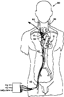
FIG. 7 is a front sectional view of a patient receiving selective
retrograde perfusion of oxygenated blood in the superior vena cava
following occlusion of a carotid artery (i.e., following a stroke). Blood
is forced retrograde in the jugular veins to oxygenate the brain. The
oxygenator and sections of the superior vena cava and jugular veins
are shown in cross-section.
FIG. 8 is a front sectional view corresponding to FIG. 7
showing the oxygenator in position within the superior vena cava.
CA 02340006 2001-02-08
WO 00/09198 PC'T/US98/16643
_$_
FIG. 9 is a front sectional view of a patient receiving selective
retrograde perfusion of oxygenated blood in the right atrium following
occlusion of a coronary artery (i.e., following a heart attack). Blood is
forced retrograde in the coronary veins to oxygenate the heart
muscle. The oxygenator and sections of the veins are shown in
cross-section.
FIG. 10 is a front sectional view corresponding to FIG. 9
showing the oxygenator in position within the superior vena cava, right
atrium of the heart, and inferior vena cava.
FIG. 11 is a front sectional view of a patient receiving selective
retrograde perfusion of oxygenated blood in the right atrium using an
alternative embodiment of the present invention following a heart
attack. The oxygenator and sections of the veins are shown in cross-
section.
FIG. 12 is a front sectional view corresponding to FIG. 11
showing the oxygenator in position within the superior vena cava, right
atrium of the heart, and inferior vena cava. The third balloon 102
connected by a separate catheter occludes the pulmonary artery 87.
CA 02340006 2001-02-08
WO 00/09198 PCT/US98/16643
_g_
The present invention provides a simple device that is rapidly
insertable into the venous system, is minimally invasive, and can
provide retrograde perfusion of oxygenated blood to compromised
organs as a result of either chronically or acutely obstructed arteries.
Organs that could be accessed with the device include: the brain
from occlusion of a vertebral, carotid or intracerebral artery; the upper
extremities from an occlusion of the subclavian artery or from spasm
of a vessel leading to that extremity; the heart from occlusion of a
coronary artery; the liver from occlusion of the hepatic artery; the
intestines from occlusion of the celiac, superior mesenteric, or inferior
mesenteric arteries; the kidney from occlusion of a renal artery; the
lower extremities from occlusion of an iliac, femoral, profundus
femoral, or popliteal artery.
The basic principle for retrograde perfusion with oxygenated
blood in the venous system under intermittent positive pressure would
be the same for all organs. The target organ is isolated with an
occluding balloon or balloons, proximal and distal to the target organ,
while oxygenated blood is pumped retrograde to the compromised
organ or target area.
Structure of Percutaneous Oxvaenator. Figures 1 through 6
illustrate two embodiments of the percutaneous oxygenator 10 used
in the present invention. FIG. 1 is a side cross-sectional view of a first
embodiment of the oxygenator 10. The major components are an
inflatable oxygenation balloon 20, a large number of hollow gas-
permeable fibers 14 that surround at least a portion of the
oxygenation balloon 20, and a smaller, inflatable occluding balloon 25
at the proximal end of the device 10. Figures 2 and 3 are cross-
sectional views corresponding to FIG.1 showing the oxygenation
CA 02340006 2001-02-08
WO 00/09198 PCT/US98/16643
-10-
balloon 20 and proximal occluding balloon 25, respectively. In both
embodiments, the oxygenation balloon 20 has an elongated shape
with gas-permeable fibers 14 surrounding its exterior surface to form a
substantially continuous sheath about the oxygenation balloon 20.
The gas-permeable walls of the fibers 14 provide a large total
surface area for diffusion of oxygen into the bloodstream and diffusion
of carbon dioxide out of the bloodstream. Any of a variety of flexible
hollow gas-permeable fibers currently available on the market, such
as Mitsubishi KPF190M polypropylene fibers, are suitable for this
purpose. The polypropylene fibers should be coated with a thin (e.g.,
1 micron or less) gas permeable membrane, such as silicone rubber,
and bonded with a non-thrombogenic component. Alternatively, multi-
layered composite hollow fiber membranes can be used for this
purpose, such as Mitsubishi MHF200L fibers. These fibers have a
composite structure with an outer layer of microporous polyethylene,
an intermediate layer of polyurethane that acts as a true membrane,
and an inner layer of microporous polyethylene.
The oxygenator includes separate lumens as shown in cross-
section in Figures 1 through 6. An external pump 21 is connected to
the lumen 16 used to inflate and deflate the occluding balloon 25, and
to the lumen 22 used to inflate and deflate the oxygenation balloon
20. Any gas or fluid can be pumped into and released from the
occluding balloon 25 and oxygenation balloon 20 for this purpose.
Helium offers the advantages of having very low viscosity and density
for ease of pumping. Carbon dioxide as an inflation gas offers safety
features and is quickly dissolved in the bloodstream in the event of
balloon leakage.
After the oxygenator 10 has been implanted as described
below, a supply or oxygen or air is connected to the lumen extending
axially along the hollow, central support 70. This hollow support 70
also helps to guide insertion of the percutaneous oxygenator 10 into
CA 02340006 2001-02-08
WO 00/09198 PCT/US98/16643
-11-
the vein. Oxygen flows through the lumen 70, enters the hollow tip
member 100 at the distal end of the oxygenator 10, and returns
through the interior passageways of the hollow fibers 14. Oxygen
diffuses outwardly through the gas-permeable walls of the fibers 14
into the surrounding bloodstream. Carbon dioxide also diffuses
inwardly from the bloodstream through these gas-permeable wails
into the interior of the fibers 14. Carbon dioxide and any remaining
oxygen in the fibers are vented to the atmosphere through lumen 27.
Negative pressurization can be applied by means of a suction pump
19 connected to lumen 27 to enhance gas flow through the fibers 14,
and to reduce any risk of gas bubbles escaping from the fibers 14 into
the bloodstream. For example, in one embodiment, oxygen is
supplied into the fibers 14 at a flow rate of approximately 1 to 3 liters
per minute and a nominal pressure of approximately 6 to 15 mm Hg.
A suction pressure of approximately -150 to -250 mm Hg is applied by
the suction pump 19.
Figure 4 is a side cross-sectional view of an alternative
embodiment of a percutaneous oxygenator 10 having a second
occluding balloon 101 at its distal end. Figures 5 and 6 are cross-
sectional views corresponding to Figure 4 taken through the
oxygenation balloon 20 and proximal occluding balloon 25,
respectively. This embodiment includes an additional lumen 102 that
enables the inflationldeflation pump 21 to independently inflate and
deflate the second occluding balloon 101.
Method of Operation. Two specific examples of methods for
using the present invention are illustrated in Figures 7 through 10. In
both cases, the oxygenator 10 is initially inserted in the venous
system through a single small incision. For example, the oxygenator
10 can be inserted through a small incision in the patient's femoral
vein 82 and then advanced upward along the inferior vena cava 83 as
depicted in Figures 7 and 9. The distal tip of the oxygenator 10 is
CA 02340006 2001-02-08
WO 00/09198 PCT/US98/16643
-12-
inserted first so that the oxygenation balloon 20 is upstream from the
occluding balloon 25. Both balloons 20, 25 remain deflated during
this insertion process. When the oxygenator 10 is in position, an
oxygen supply is connected to the central lumen 70 leading to the
gas-permeable fibers 14. The suction pump 19 is connected to the
lumen 27 drawing carbon dioxide and any remaining oxygen from the
proximal ends of the fibers 14. The balloon inflation/deflation pump
21 is connected to lumens 16, 22 to inflate and deflate the occluding
balloon 25 and oxygenation balloon 20.
Following implantation, the oxygenator 10 can be used to
induce a retrograde flow of oxygenated blood in the vein to the
compromised organ. First, the vein is occluded downstream from the
compromised organ by inflating the occluding balloon 25. Next, the
oxygenation balloon 20 is inflated to induce a retrograde flow of blood
in the vein to the compromised organ. Both balloons 20, 25 are then
deflated to allow normal antegrade flow of blood from the
compromised organ through the vein. This sequence of steps is
continuously repeated to maintain a supply of oxygenated blood to the
compromised organ. A frequency of approximately 30 to 60 cycles
per minute has been demonstrated to provide satisfactory results.
In a patient with an acute stroke from an obstructed carotid
artery, the oxygenator 10 would be inserted so as to lie in the superior
vena cava 84, or ipsilateral internal jugular vein 85. FIG. 7 is a front
sectional view of a patient 80 receiving selective retrograde perfusion
of oxygenated blood in the superior vena cava 84 following occlusion
of a carotid artery (i.e., following a stroke). FIG. 8 is a front sectional
view corresponding to FIG. 7 showing the oxygenator 10 in position
within the superior vena cava 84. During the inflation cycle, the
proximal occluding balloon 25 occludes the vein of residence when it
is fully inflated. The larger elongated oxygenation balloon 20 situated
just distal to the occluding balloon 25 is inflated in a delayed fashion
CA 02340006 2001-02-08
WO 00/09198 PCT/US98/16643
-13-
after the occluding balloon 25 is inflated, thus propagating a pulsatile
wave in the retrograde direction through the jugular veins 85 to supply
oxygenated blood to the brain. During the deflation cycle, both
balloons 20, 25 would empty, allowing venous blood to drain from the
brain. The end result is that highly oxygenated blood would be
supplied to the brain, not through the normal arterial pathway, but
retrograde through the venous system. Such a configuration of the
oxygenation balloon 20 and fibers 14 would also suffice for supplying
blood to the upper extremities (vein of choice for implant, the
subclavian vein) or the lower extremities (vein of choice for implant,
the femoral vein).
FIG. 9 is a front sectional view of a patient 80 receiving
selective retrograde perfusion of oxygenated blood in the right atrium
86 following occlusion of a coronary artery (i.e., following a heart
attack). Blood is forced retrograde in the coronary veins to oxygenate
the heart muscle using the alternative embodiment of the oxygenator
10 with two occluding balloons 101, 25 as shown in Figures 4 through
6. FIG. 10 is a front sectional view corresponding to FIG. 9 showing
the oxygenator 10 in position within the superior vena cava 84, right
atrium 86 of the heart 81, and inferior vena cava 83. With these
occluding balloons 101, 25 thus situated in the superior and inferior
vena cavas 84 and 83, the oxygenation balloon 20 resides in their
middle and is positioned in the right atrium 86.
In normal antegrade blood circulation, the cardiac veins drain
the capillary networks of the myocardium and drain into the right
atrium 86 by way of the coronary sinus, or drain directly into the right
atrium 86. In contrast, the present invention reverses this flow by
forcing oxygenated blood retrograde from the right atrium into the
coronary sinus during balloon inflation and thereby nourishes the
heart.
CA 02340006 2001-02-08
WO 00/09198 PCT/I1S98/16643
-14-
Figures 11 and 12 depict yet another embodiment of the
present invention having a third inflatable balloon 102 that is similar to
occluding balloons 101 and 25, but is used to occlude the pulmonary
artery 87. This provides a more complete isolation of the right atrium
86 and right ventricle. The oxygenation balloon 20 thereby becomes
more effective in directing a flow of oxygenated blood from the right
atrium 86 into the coronary sinus since blood is no longer capable of
exiting via the pulmonary artery 87.
In the embodiment shown in Figures 11 and 12, the third
balloon 102 is inflated and deflated through a separate catheter that
branches off the main catheter leading to the other balloons 101, 25.
The third balloon is inserted through a small incision in the femoral
vein 82 and then advanced upward along the inferior vena cava 83. It
is then advance through the right atrium 86 and the right ventricle of
the heart into the pulmonary artery 87. After implantation, the balloon
inflation/deflation pump 21 is connected to the catheter leading to the
third balloon 102 so that it will be periodically inflated and deflated in
the same manner as the other balloons 101, 25.
For the kidney, liver, or intestines, two occluding balloons 25,
101 in the inferior vena cava would also be necessary, positioned
proximal and distal to the organ of concern. The oxygenation balloon
20 is located between the two occluding balloons 25, 101 and during
inflation its transmitted pulse would be isolated from the rest of the
venous system, thus forcing oxygenated blood retrograde up the
compromised organ to supply oxygen. As in all instances during the
deflation cycle, blood is allowed to drain from the compromised organ,
thus preventing engorgement and edema of the organ.
The above disclosure sets forth a number of embodiments of
the present invention. Other arrangements or embodiments, not
precisely set forth, could be practiced under the teachings of the
present invention and as set forth in the following claims.