Note: Descriptions are shown in the official language in which they were submitted.
CA 02340816 2001-03-14
99-PDC-034 1
SUPPORT AND ALIGNMENT STRUCTURE FOR
MAGNETIC TRIP DEVICE
BACKGROUND OF THE INVENTION
Field of the Invention
This invention relates to a magnetic trip device for circuit breakers and,
more
specifically, to a support structure which maintains the alignment of a
plunger in the
magnetic trip device.
Description of the Prior Art
Molded case circuit breakers are well known in the art as exemplified by U.S.
Pat. No. 5,927,484 to Malingowski issued July 27, 1999 and by U.S. Patent No.
4,503,408 issued March 5,1985 to Mrenna et.al., entitled "Molded Case of
Circuit
Apparatus Having Trip Bar With Flexible Armature Interconnection" assigned to
the
assignee of the present application. The foregoing are incorporated herein by
reference.
In molded case circuit breakers in which the power contacts, operating
mechanism, and trip unit are mounted inside of a molded plastic insulative
housing, a
common type of magnetic trip device is a solenoid which includes a stationary
core
through which the current in the protected circuit is passed. The current
passing
through the stationary core creates a magnetic field. When there a very high
instantaneous currents, such as those associated with a short circuit, the
magnetic field
intensifies. A plunger assembly, having a moveable core and a plunger tab
which
engages the trip latch on the operating mechanism, is partially disposed
within the
stationary core. Typically, a spring provides a limited force biasing the
movable core
away from the stationary core and preventing the plunger from engaging the
trip latch.
The force of the spring is overcome by the magnetic field generated by the
stationary
CA 02340816 2001-03-14
99-PDC-034 2
core during a short circuit. That is, when a short circuit occurs, the current
in the
stationary core creates a magnetic field strong enough to overcome the
moveable core
spring thereby allowing the moveable core to move toward the stationary core
and
causing the plunger to engage the trip latch.
The amount of current required to trip the device can be controlled by
adjusting the amount of separation between the plunger assembly and stationary
core.
When the plunger assembly is located closer to the stationary core, a weaker
magnetic
field, and therefore a lower current, is required to draw the plunger assembly
toward
the stationary core to trip the device. In order to adjust the trip condition,
the plunger
assembly is mounted in a plunger assembly support structure having a base and
a
moveable plunger carriage. The carriage allows the plunger assembly, including
the
moveable core, to be moved relative to the stationary core. A carriage is used
so that
adjusting the gap between the moveable core and the stationary core does not
impact
on the compression of the moveable core biasing spring. The moveable plunger
carriage is coupled to an adjustment mechanism to address the initial gap
between the
plunger assembly and the stationary core.
Plunger assembly support structures of the prior art were loosely disposed
within plunger carriage cavities in the circuit breaker housing. Such support
structures did not include a means to maintain the alignment of the plunger
carriage
relative to the base or the stationary core. As such, the plunger carriage
could wobble
in the plunger carrier cavity, resulting in a mis-alignment of the plunger
assembly.
Additionally, through repeated use, the moveable core on prior art magnetic
trip
devices can rotate allowing the plunger tab to move away from the trip bar
actuator
arm.
There is a need, therefore, for a plunger assembly support structure for a
molded case circuit breaker magnetic trip mechanism which maintains the
orientation
of the plunger carriage in the circuit breaker housing.
There is a further need for a plunger assembly support structure for a molded
case circuit breaker magnetic trip mechanism which provides a means for
maintaining
the moveable core alignment with the stationery core.
CA 02340816 2001-03-14
99-PDC-034 3
There is a further need for a plunger assembly support structure for a molded
case circuit breaker magnetic trip mechanism which corrects rotation of the
plunger
tab on the moveable core.
SUMMARY OF THE INVENTION
These needs and others are satisfied by the invention which provides a plunger
assembly support structure for a magnetic trip unit which includes a plurality
of
guides which maintain the orientation of the plunger carriage. This invention
further
provides a plunger guide which corrects rotation of the moveable core of the
solenoid.
A molded case circuit breaker includes at least one pair of separable main
contacts. The main contacts are disposed in the circuit breaker housing. The
circuit
breaker may be tripped manually by a handle or by a magnetic trip device. The
magnetic trip device includes a rotating trip bar, which is actuated by a
plunger
assembly, a moveable plunger assembly and a stationary core. The stationary
core is
in disposed between, and in electrical communication with, the main contact
and the
load side of the circuit breaker. The plunger assembly includes a moveable
core,
partially disposed within the stationary core. The plunger assembly is
disposed within
a plunger assembly support structure having a base assembly and a movable
plunger
carriage. The base assembly is coupled to the circuit breaker housing. The
plunger
carriage is coupled to the base. The base includes a plurality of guides which
align the
plunger carriage and plunger with the trip bar. The base assembly further
includes a
conical indentation which reorients the plunger if it rotates in the plunger
carriage.
BRIEF DESCRIPTION OF THE DRAWINGS
A full understanding of the invention can be gained from the following
description of the preferred embodiments when read in conjunction with the
accompanying drawings in which:
Figure 1 is a partial cut away view of a circuit breaker housing incorporating
the plunger carriage according to the present invention.
Figure 2 is an isometric view of a circuit breaker with the top covers and
plunger carriages removed.
Figure 3 is an isometric view of the circuit breaker mechanism without the
circuit breaker housing.
CA 02340816 2001-03-14
99-PDC-034 4
Figure 4 is an isometric view of a plurality of plunger carriage support
structure according to the present invention.
Figure 5 is an isometric view of a single plunger carriage support structure
according to the present invention.
Figure 6 is an exploded view of the plunger carriage according to the present
invention.
Figure 7 is an isometric view of the plunger locator feature.
Figure 8 is a front view of the plunger locator feature.
DETAILED DESCRIPTION OF THE PREFERRED EMBODIMENTS
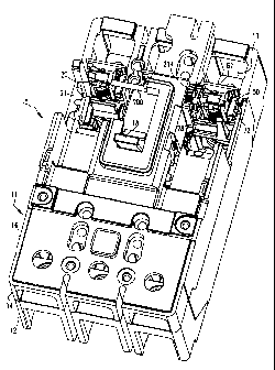
Referring to the drawings, Figure 1 shows a molded case circuit breaker 10
according to a preferred embodiment of the present invention. The molded case
circuit breaker has a housing 11, which includes a base portion 12 which is
coupled to
a primary cover 14. Base portion 12 includes a plurality of cavities 13 which
support
the circuit breaker components (described below). Disposed on top of primary
cover
14 is a secondary cover 16. An operating handle 18 protrudes through secondary
cover 16. As shown in Figs. 2 and 3, at least one pair of main contacts 2, 4
are
disposed within housing 11. The contacts include a moveable contact 2, and a
stationary contact 4. The movable contact 2 is coupled to and is in electrical
communication with the load side of the circuit breaker 10. The stationary
contact 4
is coupled to and is in electrical communication with an electrical line (not
shown).
Handle 18 is coupled to a moveable contact 2 within the circuit breaker
housing 11.
Handle 18 may be used to reset the circuit breaker 10 after it has been
tripped or may
be used to manually open or close the circuit breaker 10.
The circuit breaker 10 may be tripped by a separate magnetic trip assembly 20.
The magnetic trip assembly 20 cooperates with a rotating trip bar 21, which is
coupled to a latchable operating mechanism 24. As is known in the prior art,
rotation
of trip bar 21 will release the latchable operating mechanism 24 allowing the
circuit
breaker 10 to trip. The trip bar 21 includes at least one actuating arm 26,
which is
adjacent to the magnetic trip assembly 20.
The magnetic trip assembly 20 includes a stationary core 22, a plunger
assembly 28 and a plunger assembly support structure 50. Stationary core 22 is
disposed within a cavity 13 in the bottom housing 12 and forms a portion of
the load
circuit through the breaker 10. The stationary core 22 is preferably shaped as
a coil.
CA 02340816 2001-03-14
99-PDC-034 5
The stationary core 22 includes a medial aperture 25, preferably having a
circular
cross-section. The stationary core 22 is disposed between the moveable main
contact
2 and a load side of the breaker 10. When electricity flows through the
stationary
core 22 a magnetic field generating a magnetic force is created.
Figure 4 shows a plurality of plunger assembly support structures 50 linked to
each other by cam shaft 200. For ease of identification, certain components
are
identified on separate units, however, it is understood each unit includes
each
identified component. Plunger assembly 28 includes a moveable core 30 having a
flattened end 31, a coil spring 34 and a plunger tab 36. The movable core 30
is
preferably a solid metal cylinder. Coil spring 34 is disposed about moveable
core 30.
As shown on Figs. 2 and 3, the plunger assembly 28 is disposed within cavity
88 of
plunger assembly support structure 50 (described below). One end of coil
spring 34
contacts flattened end 31 while the other end contacts the support structure
50.
As shown in Figs. 4-6, the plunger assembly support assembly 50 includes a
base member assembly 52 and a plunger carriage assembly 54. The plunger
assembly
28 is disposed within the plunger carriage assembly 54. The plunger carriage
assembly 54 is slidably disposed adjacent to the base member assembly 52. The
plunger carriage assembly 54 is slidabe so that the distance between the
moveable
core 30 and the stationary core 22, and therefore the trip condition of the
circuit
breaker 10, may be selectively adjusted.
Base member assembly 52 includes a mounting tab 60, a body 62 having a
first face 66. The base member 52 further includes a plurality of guides 70
extending
from the body first face 66. The guides 70 are spaced to fit on either side of
the
plunger carriage assembly 54 (described below). The guides 70 are positioned
so that
at least two guides 70 are on one side of plunger carriage assembly 54, and at
least
one guide 70 is on the opposite side of plunger carriage assembly 54. Body 62
further
includes a spring housing 72 extending from the body first face 66. Any of the
guides
70 or spring housing 72 may include guide grooves 76 shaped to cooperate with
an
alignment ridge 102 (described below). The body 62 also includes a camshaft
nest 74.
CA 02340816 2001-03-14
99-PDC-034 6
As shown in Figs. 7 and 8, the housing body 62 includes a plunger guide 120,
which, during movement of the plunger carriage assembly 54, automatically
realigns
the plunger tab 36 with the actuating arm 26. The plunger guide 120 includes a
conical cut out 122 located on the body first face 66. The conical indentation
122 is
positioned on the body first face 66 so that it will be adjacent to the
plunger tab 36
when the moveable core 30 is disposed within cavity 88. The wide end of the
conical
indentation 122 is adjacent to tab 60. The conical indentation 122 may also
include a
plunger trough 124 extending from the narrow portion of the conical
indentation 122
toward camshaft nest 74.
The plunger carriage assembly 54 includes a first side member 80 and a
second side member 82, shown in Figs. 3 and 4. The first side member 80 and
the
second side member 82 are held in spaced relation by a top member 84 and a
bottom
member 86. An open-faced cavity 88 is formed between the first side member 80
and
the second side member 82. Both the first side member 80 and the second side
member 82 each have an interior side 90 (Fig. 5), 92 (Fig. 4) and an exterior
side 94
(Fig. 4), 96 (Fig. 5) respectively. The second side member exterior side 96
includes a
spring tab 100 extending therefrom. The first side member exterior side 94 has
an
alignment ridge 102 (Fig. 4). The second side member exterior side 96 also has
an
alignment ridge 102 (Fig. 5). As will be described below, the alignment ridges
102
are disposed in guide grooves 76 when the plunger carriage assembly 54 is
disposed
adjacent to base member assembly 52.
As noted above, the plunger carriage assembly 54 is slidably disposed adjacent
to base member assembly 52. The plunger carriage assembly 54 is slidable
between a
first and second position. In the first position, bottom member 86 is located
the
maximum distance from camshaft nest 74. In the second position, bottom member
86
is located the minimum distance from camshaft nest. 74. The plunger carriage
assembly 54 is disposed adjacent to base member assembly 52 such that two
guides
70 are adjacent to and contacting first side member exterior side 94 and one
guide 70
and spring housing 72 are adjacent to and contacting second side member
exterior
side 96. Alignment ridges 102 are disposed within guide grooves 76. Alignment
ridges 102 have a sufficient length so that a portion of alignment ridge 102
remains in
guide groove 76 as plunger carriage assembly 54 slides between the first and
second
positions. When coupled in this fashion, the plunger carriage assembly 54 is
CA 02340816 2001-03-14
99-PDC-034 7
maintained in alignment relative to the base member assembly 52 by virtue of
at least
three contact points on side exterior surfaces 94, 96. Additionally, alignment
ridges
102 cooperate with guide grooves 76 to prevent the plunger carriage assembly
54
from separating from body 62 in a direction normal to first face 66.
A spring member 110 may be disposed between the spring housing 72 and
spring tab 100. In the preferred embodiment, a helical compression spring is
used.
The spring biases the plunger carriage assembly 54 in the first position.
The strength of the magnetic force, which changes in relation to the amount of
current through stationary core 22, necessarily acting on the plunger assembly
28 is a
function of the distance between the stationary core 22 and the moveable core
30.
Accordingly, the over-current situation for breaker 10 may be adjusted by
moving the
moveable core 30 closer or further from the stationary core 22. When the
moveable
core 30 is closer to stationary core 22, the strength of the magnetic force,
and
therefore the amount of current through stationary core 22, required to
overcome the
bias of coil spring 34 is reduced as compared to the magnetic force, and
therefore
current through stationary core 22, required to overconie the bias of coil
spring 34
when moveable core 30 is further from stationary core 22. The plunger carriage
assembly 54, which supports the plunger assembly 28 and moveable core 30, is
slidably disposed adjacent to base member assembly 52 to accomplish this
adjustment.
In operation plunger assembly support structure 50 may be coupled to the
circuit breaker housing 11 in a base portion cavity 13. Tab 60 cooperates with
cavity
13 to position plunger assembly support structure 50 so that the end of
moveable core
opposite flattened end 31 is partially disposed in stationary core aperture
25.
25 When so disposed, the magnetic force generated by electric current through
stationary
core 22 acts on moveable core 30 of plunger assembly 28, as explained above.
Additionally, when plunger assembly support structure 50 is coupled to cavity
13,
plunger tab 36 is positioned adjacent to trip bar actuating arm 26. Under
normal
operating conditions, coil spring 34 overcomes the magnetic force created by
the
30 electric current through stationary core 22 and biases flattened end 31 of
moveable
core away from plunger carriage bottom member 86 and stationary coil 22. The
CA 02340816 2001-03-14
99-PDC-034 8
biasing force of coil spring 34 also prevents plunger tab 36 from engaging
trip bar
actuating arm 26.
When an over-current situation occurs, however, the magnetic force created by
the current through stationary core 22 increases in strength. When the
magnetic force
becomes strong enough to overcome the bias of coil spring 34, the plunger
assembly
28 is drawn towards stationary core 22. As the plunger assembly 28 is drawn
towards
stationary core 22, plunger tab 36 engages trip bar actuating arm 26 causing
the trip
bar 21 to rotate clockwise as view in Fig. 3. When trip bar 21 rotates,
latchable
operating mechanism 24 is released allowing the circuit breaker 10 to trip.
When the
plunger assembly 28 moves, either because of an over-current or due to
adjustment by
a user, but for the guides 70 the plunger assembly 28 may become misaligned
relative
to the stationary core 22 or the trip bar actuating arm 26. Guides 70
maintains the
alignment of plunger carriage assembly 54, and therefore the plunger assembly
28,
relative to the stationary core 22 or the trip bar actuating arm 26.
Additionally,
alignment ridges 102 cooperate with guide grooves 76 to prevent the plunger
carriage
assembly 54 from separating from body 62 in a direction normal to first face
66.
Alignment of the plunger assembly 28 within the plunger carriage assembly
54 is accomplished by a plunger guide 120 on body 62. During the use of the
trip
mechanism, it is possible for the moveable core 30 to rotate axially, thereby
allowing
plunger tab 36 to move out of alignment with the actuating arm 26. The plunger
tab
36 contacts the plunger guide 120. Conical indentation 122 becomes narrower as
it
extends toward camshaft nest 74. As the plunger carriage assembly 54 travels
from
the first position towards the second position, the plunger tab 36 contacting
the
conical indentation 122 rotates the moveable core 30 so that the plunger tab
36 is
aligned with the actuating arm 26.
While specific embodiments of the invention have been described in
detail, it will be appreciated by those skilled in the art that various
modifications and
alternatives to those details could be developed in light of the overall
teachings of the
disclosure. Accordingly, the particular arrangements disclosed are meant to be
illustrative only and not limiting as to the scope of invention which is to be
given the
full breadth of the claims appended and any and all equivalents thereof.