Note: Descriptions are shown in the official language in which they were submitted.
CA 02340915 2001-02-16
WO 00/28932 PCT/US99/19405
WHEELCHAIR SUSPENSION SYSTEM
FIELD OF SHE INVENTION
The invention relates to suspension systems and in particular
to a suspension system for a wheelchair. More particularly, the present
invention is directed to a suspension system for a wheelchair, which
provides for a relatively large amount of substantially vertical travel of
the wheels of the wheelchair when bumps, depressions or other irregu-
larities in the wheelchair travel surface are encountered by the wheels.
BACKGROUND ART
Since the inception of the wheelchair, manufacturers and
users of this device have continually attempted to improve its comfort,
operation, portability, and appearance. One area of ongoing concern is
the capability of the wheelchair to exhibit excellent shock absorption
characteristics while at the same time being cost-effective and light-
weight. A suspension system, of the type similar to those that can be
found on other types of wheeled vehicles such as cars and trucks, is in-
corporated in a vehicle for several reasons. One reason is to absorb
shocks and thereby insulate from shocks the people and/or cargo being
carried by the vehicle. For example, during use of a wheelchair, small
bumps, depressions or other irregularities on the surface on which the
wheelchair is traveling can cause such shocks. Another common objec-
tive of a vehicle suspension that also applies to wheelchairs is to main-
tain all of the wheels of the vehicle on the ground when such relatively
small bumps or depressions are encountered, in order to maintain
steering control and stability of the vehicle. However, unfortunately,
many known suspension systems are too expensive and/or too heavy
for incorporation into many of today's lightweight and relatively inex-
pensive wheelchairs.
CA 02340915 2001-09-06
2
The present invention solves the above-described problems by
incorporating a relatively simple, inexpensive, lightweight, yet
effective suspension assembly adjacent to each wheel of the
wheelchair, which in turn provides a relatively large amount of
substantially vertical wheel displacement for absorbing shocks and
for maintaining the steering control and stability of the
wheelchair.
STJMMARY OF INVENTION
Objectives of the present invention include providing a
wheelchair suspension system which absorbs and insulates the
occupant of the wheelchair from shocks when relatively small
bumps, depressions or other irregularities in a travel surface are
encountered by the wheelchair.
Another objective of the present invention is to provide
such a wheelchair suspension system in which all wheels of the
wheelchair are maintained in constant contact with the travel
surface when sch bumps, depressions or other irregularities in the
travel surface are encountered by the wheelchair, thereby
maintaining occupant steering control and stability of the
wheelchair.
A further objective of the present invention is to provide
such a wheelchair suspension system which is economical to
manufacture and install on a wheelchair, lightweight and reliable
in use.
These objections and advantages are obtained by the
provision of a wheelchair having a pair of drive wheels, each of
said drive wheels being rotatably mounted on an axle on a first
and a second lateral side of the wheelchair and supporting a frame
member of said wheelchair with a suspension system operably
interposed between the frame member and the axle of said
wheelchair, each of said suspension systems comprising an upper
arm having a first and a second end, said upper arm pivotally
connected at its first end to said axle and its second end to said
frame member; a lower arm having a first and a second end, said
lower arm pivotally connected at its first end to said axle and at
CA 02340915 2001-09-06
3
its second end to said frame member; and a spring operatively
connected between said upper arm and said lower arm, wherein said
suspension system is capable of moving said respective axle in a
substantially vertical direction.
BRIEF DESCRIPTION OF THE DRAWINGS
The preferred embodiment of the invention, illustrative of
the best mode in which applicants has contemplated applying the
principles, is set forth in the following description and is shown
in the drawings and is particularly and distinctively pointed out
and set forth in the appended claims.
FIG. 1 is a rear perspective view showing one type of wheel-
chair on which the suspension system of the present invention is
incorporated.
FIG. 2 is an enlarged view similar to FIG. 1, but with one
of the wheels of the wheelchair removed to reveal the suspension
assembly disposed adjacent to the removed wheel;
FIG. 3 is a left-hand side view of the wheelchair shown in
FIG.2;
FIG. 4 is an enlarged front perspective view of the
suspension system of the present invention, shown mounted on he
axle of the wheelchair and with other parts of the wheelchair
removed;
FIG.5A is an enlarged fragmentary side view of one of the
suspension assemblies of the suspension system, shown mounted on
the axle and the frame of the wheelchair, and with other parts of
the wheelchair removed;
FIG.SB is a rear perspective view of the parts shown in FIG.
5A;
FIG.6A is an enlarged view similar to FIG.SA, but without
showing any portion of the wheelchair frame, and showing the
substantially vertical upward displacement of the axle when a bump
is encountered in the travel surface of the wheelchair; and
CA 02340915 2001-02-16
WO 00/28932 PCT/US99/19405
4
FIG. 6B is a view similar to FIG. 6A, and showing the sub-
stantially vertical downward displacement of the axle when a depres-
sion is encountered in the travel surface of the wheelchair.
Similar numerals refer to similar parts throughout the draw-
S ings.
DESCRIPTION OF THE PREFERRED EMBODIMENT
The suspension system of the present invention is indicated
generally at 10, and is shown in FIG. 1 incorporated into a wheelchair
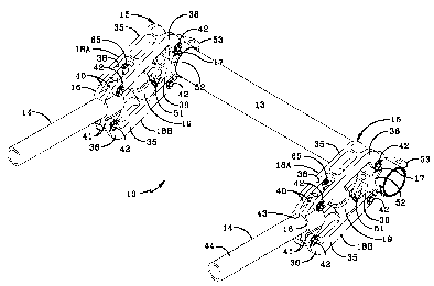
1 1 having a frame 12 and an axle 13. As best shown in FIGS. 2 and 4,
suspension system 10 includes a pair of suspension assemblies 15
which are identical in structure and operation, so that only one suspen-
sion assembly will be described hereinbelow. Suspension assembly 15
includes a front bracket 16 and a frame extension 14 for attaching the
suspension assembly to wheelchair frame 12, a rear bracket 17 for at-
taching the suspension assembly to one end of wheelchair axle 13, top
and bottom arms 18a and 18b, respectively, each of which is pivotally
attached to the front and rear brackets, and a spring 19 disposed be-
tween and interconnecting the top and bottom arms. Suspension as-
sembly 15 is a trailing arm type suspension assembly, but it is under-
stood that the concepts of the present invention also are applicable to
leading arm or transverse arm suspension assemblies.
Suspension system 10 of the present invention is shown in
FIGS. 1 through 3 incorporated into wheelchair 1 1 of the type which
generally is considered to be a lightweight sport wheelchair useful in
outdoor and indoor sporting activities. However, it is understood that
the present invention can be utilized on other types of wheelchairs, in-
cluding non-rigid or folding wheelchairs which are free of an axle which
extends between and interconnects the two main wheels of the wheel-
chair, thereby making the wheelchair collapsible. However, so that one
environment in which suspension system 10 can be used will be better
understood, wheelchair 1 1 will be described in greater detail. As set
CA 02340915 2001-02-16
WO 00/28932 .pCT/US99/19s105
forth hereinabove, wheelchair 1 1 includes frame 12 and axle 13.
Wheelchair 11 further includes a seat 25 mounted on frame 12,
wherein the seat includes a horizontal bottom portion 26 and a vertical
back support 27. A manually operable drive wheel 28, of a type which
5 is well known in the wheelchair art, is mounted on each end of axle 13
in a usual manner. A pair of swivel casters 29 is mounted in spaced-
apart relationship on the front of frame 12 forwardly from wheels 28.
A footrest 30 also is mounted on the front of frame 12 between casters
29. It should be noted that wheelchair 1 1 of the type shown in FIGS. 1
to 3 typically is utilized in sporting activities such as basketball and the
like, due to its light weight and stability as welt as its ability to with-
stand side loads because of the interconnection of wheels 28 by axle
13. Moreover, it is understood that in this type of sport wheelchair 11,
wheels 28 each are conventionally mounted on frame 12 with a camber
15 (not shown), that is, the bottom portions of the wheels are set apart a
greater transverse distance than are the top portions of the wheels.
Suspension assembly 15 and its incorporation into wheelchair
1 1 now will be described in detail. The components of suspension as-
sembly 15 are formed of any suitable sturdy material such as metal,
20 except where nated. Top and bottom suspension assembly arms 18a,
b each is a generally L-shaped member (FIG. 5A). Each L-shaped arm
18a, b includes an elongated section 35 and a short section 36. Each
short arm section 36 is formed with a cutout 37 (FIG. 5B) and a pair of
spaced-apart transversely aligned openings (not shown). Similarly, each
25 elongated arm section 35 is formed with a cutout 38 (FIG. 4) and a pair
of spaced-apart transversely aligned openings (not shown).
Front bracket 16 is formed with a first pair of spaced-apart
upwardly extending ears 40 and a second pair of spaced-apart down-
wardly extending ears 41 (FIG. 4). Each ear 40, 41 is formed with an
30 opening (not shown), and each pair of ears is spaced apart a distance
wherein the outermost surface of each ear abuts an innermost surface
of its respective arm cutout 37, 38. The openings of first pair of ears
CA 02340915 2001-02-16
WO 00/28932 . PCT/US99/19405
6
40 are aligned with top arm elongated section 35 openings and the
openings of second pair of ears 41 are aligned with bottom arrn short
section 36 openings. A suitable fastener 42 is passed through the
aligned openings of top arm elongated section 35 and first pair ears 40
5 to pivotally secure top arm 18a to bracket 1 fi. Similarly, another fas-
tener 42 is passed through the aligned openings of bottom arm short
section 36 and second pair ears 41 to pivotally secure bottom arm 18b
to bracket 16. Bracket 16 also is formed with a central opening 43
(FIG. 5B) for insertion of the rear end of frame extension 14, and the
10 front end of the frame extension is inserted into frame 12. More spe-
cifically, wheelchair frame 12 and frame extension 14 each is formed of
a tube-shaped metal, and the outside diameter of extension 14 is nomi-
nally smaller than the inside diameter of a rearwardly extending frame
tube 44 and central bracket opening 43. The rear end of extension 14
15 is immovably secured in bracket opening 43 by any suitable means
such as welding, and the front end of the extension is adjustably se-
cured in the frame tube by a cam clamp mechanism 45 of a type that is
well known to the art and to the literature (FIGS. 2, 3, 5A and 5B)
However, although clamp 45 is preferred, it is understood that any type
20 of clamp mechanism, set screw or the like could be used to adjustably
secure extension tube 14 within frame tube 44. It should further be
appreciated that the depth of insertion of each extension tube 14 within
its respective frame tube 44 determines the front-rear position of
wheels 28 relative to frame 12 and seat 25, thereby determining the
25 center of gravity of wheelchair 11.
Rear bracket 17 similarly is formed with a first pair of spaced-
apart upwardly extending ears 50 and a second pair of spaced-apart
downwardly extending ears 51 (FIGS. 4 and 5B). Each ear 50, 51 is
formed with an opening (not shown), and each pair of ears is spaced
30 apart a distance wherein the outermost surface of each ear abuts an in-
nermost surface of its respective arm cutout 37, 38. The openings of
first pair of ears 50 are aligned with top arm short section 36 openings
CA 02340915 2001-02-16
WO 00/28932 PCT/US99/19405
7
and the openings of second pair of ears 51 are aligned with bottom arm
elongated section 35 openings. A fastener 42 is passed through the
aligned openings of top arm short section 36 and first pair ears 50 to
pivotally secure top arm 18a to bracket 17. Similarly, another fastener
5 42 is passed through the aligned openings of bottom arm elongated
section 35 and second pair ears 51 to pivotally secure bottom arm 18b
to bracket 17. The rear surface of bracket 17 is attached to a saddle
52 such as by welds Inot shown), and the saddle in turn is similarly at-
tached to a cam clamp mechanism 53 which in turn is slidably mounted
on the end of axle 13.
Spring 19 includes top and bottom cylindrical-shaped solid
members 61, 62, respectively, with each member being formed of an
elastomer having a type A durometer of from about 50 to about 100,
preferably from about 60 to about 90, and most preferably from about
70 to about 80. An isolation plate 60 is disposed between and inter-
connects top and bottom members 61, 62 to provide additional stability
to spring 19. As best shown in FIGS. 4 and 6A, spring 19 is mounted
on and extends between elongated section 35 of top and bottom arms
18a, b by a pair of fasteners 65 of a type which are well known to one
skilled in the spring art.
The operation of suspension system 10 of the present inven-
tion, and in particular each suspension assembly 15 thereof, can now
be described. In its resting position, as best shown in FIG. 5A, a hori-
zontal distance between the rear surface of bracket 16 and a central
axis of axle 13 is represented by D. Moreover, a vertical distance be-
tween the central axis of axle 13 and a central axis of frame extension
14 is represented by H. In addition, a distance between the lowermost
and uppermost surfaces of elongated sections 35 of top and bottom
arms 18a, b, respectively, is represented by A. It can be seen in FIG.
6A that when a bump is encountered by one or both wheels 28 of
wheelchair 1 1, arms 18 pivot about brackets 16 and 17 at fasteners 42
as axle 13 moves upward in response to the bump. This pivoting ac-
CA 02340915 2001-02-16
WO 00/28932 PCT/US99/194(15
8
tion causes arms 18a, b to visibly move close together from distance A
(FIG. 5A) to distance A-z, where z is variable, and spring 19 corre-
spondingly is compressed to absorb the shock of wheel 28 moving over
the bump. However, elangated section 35 of each arm 18 remains
S parallel to the elongated section of the other arm, thereby enabling a
relatively large amount of vertical travel H+y, where y is variable, of
axle 13 and only a nominal amount of horizontal travel D-x, where x is
variable, of the axle, thereby providing efficient absorption of up to
about 50% of the shock by suspension assembly 15.
Turning now to FIG. 6B, it can be seen that when one or both
wheels 28 of wheelchair 1 1 encounters a depression in the travel sur-
face of the wheelchair, arms 18 again pivot about brackets 16, 17 at
fasteners 42 as axle 13 moves downward in response to the depres-
sion. This pivoting action causes arms 18a, b to visibly move farther
1S apart from distance A to distance A + z, and spring 19 correspondingly
is placed under tension to absorb the shock of wheel 28 dropping into
the depression. Elongated section 35 of each arm 18 again remains
parallel to the elongated section of the other arm, thereby enabling a
relatively large amount of vertical travel H-y of axle 13 and only a
nominal amount of horizontal travel D+x of the axle, again resulting in
efficient absorption of up to about 50% of the shock by suspension as-
sembly 15.
In accordance with one of the main features of the present
invention, it should be understood that the displacement of axis 13 in a
2S substantially vertical direction when a bump or depression is encoun-
tered in the travel surface of wheelchair 11, is an important factor in
maintaining the center of gravity of the occupied wheelchair. This sub-
stantially vertical axle displacement also aids in keeping all of the
wheels of the wheelchair in contact with the travel surface, to maintain
the stability and steering control of the wheelchair. Moreover, suspen-
sion assembly 15 prevents axle 13 from traveling substantially in an
arc, which in turn prevents toe-in of the already cambered wheels,
CA 02340915 2001-02-16
WO 00/28932 PCT/US99/19405
9
which in turn also aids in maintaining all of the wheels in contact with
the travel surface when irregularities in that surface are encountered.
Thus, it can be seen that the suspension system 10 of the
present invention is useful on wheelchairs of any type to provide shock
absorption and stability to the wheelchair when bumps, depressions or
other irregularities in the travel surface of the wheelchair are encoun-
tered. Moreover, it can be seen that suspension system 10 is economi-
cal to make and install, reliable in use, and lightweight and easy to
maintain.
10 Accordingly, the wheelchair suspension system of the present
invention is simplified, provides an effective, safe, inexpensive and effi-
cient suspension system which achieves all of the enumerated objec-
tives, provides for eliminating difficulties encountered with prior wheel-
chair suspension systems, and solves problems and obtains new results
in the art.
In the foregoing description, certain terms have been used
for brevity, clarity, and understanding; but no unnecessary limitations
are to be implied therefrom beyond the requirements of the prior art,
because such terms are used for descriptive purposes and are in-
tended to be broadly construed.
Moreover, the description and illustration of the invention is
by way of example, and the scope of the invention is not limited to
the exact details shown or described.
Having now described the features, discoveries and princi-
25 ples of the invention, the manner in which the wheelchair suspension
system is constructed, arranged, and used, the characteristics of the
construction and arrangement, and the advantageous, new and useful
results obtained; the new and useful structures, devices, elements, ar-
rangements, parts, and combinations are set forth in the appended
claims.